

Kannad Marine Rescuer 2 SART User Manual
Kannad Marine Rescuer 2
SEARCH & RESCUE
TRANSPONDER
USER MANUAL

WARNING
i This SART is an emergency device for use only in situations of
grave and imminent danger.
i False alarms cost lives and money. Help to prevent them;
understand how to activate and disable your equipment.
i Read the complete manual before installing, testing or using the
SART.
i The SART contains no user serviceable parts. Return to your dealer
for service.
i Dispose of this device safely. Contents include Lithium batteries;
do not incinerate, puncture, deform or short-circuit.
i This device emits radio frequency radiation when activated.
Because of the levels and duty cycles, such radiation is not classed
as harmful. However, it is recommended that you do not hold the
radome while the SART is activated.
i If the security tab is broken, the SART is not compliant with SOLAS
regulations and must be repaired or replaced.
Transportation
The SART contains a primary non-rechargeable Lithium battery, and may have
special transportation requirements depending on local and international
regulations in force at the time.
The battery pack contains 6.2g Lithium in total. Transport the SART in
compliance with applicable regulations for this mass of hazardous material.
For further information refer to the Kannad Marine website: -
www.kannadmarine.com
Disclaimer
The information and illustrations contained in this publication are to the best of our
knowledge correct at the time of going to print. We reserve the right to change
specifications, equipment, installation and maintenance instructions without notice as
part of our policy of continuous product development and improvement. No part of this
publication may be reproduced, stored in a retrieval system or transmitted in any form,
electronic or otherwise without permission in writing from Kannad Marine. No liability can
be accepted for any inaccuracies or omissions in the publication, although every care has
been taken to make it as complete and accurate as possible.

CONTENTS
1.
2.
3.
4.
5.
6.
7.
8.
9.
10.
11.
12.
13.
13.1
13.2
13.3
13.4
13.5
13.6
13.7
13.8
13.9
14
15
16
16.1
16.2
General Description .............................................................. 2
SART principle of operation ................................................. 3
Installation ............................................................................. 5
SART General Assembly ...................................................... 6
Operating instructions .......................................................... 7
Self test facility...................................................................... 8
Battery replacement ............................................................. 9
Technical description ......................................................... 10
Function chart ..................................................................... 11
Fault Finding ....................................................................... 11
Servicing.............................................................................. 11
Dimensions ......................................................................... 12
Operation of marine radar for SART detection ................. 13
Radar Range Scale..............................................................................13
SART Range Errors .............................................................................13
Radar Bandwidth .................................................................................13
Radar Side Lobes ................................................................................13
Detuning the Radar ..............................................................................13
Gain ....................................................................................................13
Anti-Clutter Sea Control .......................................................................14
Anti-Clutter Rain Control ......................................................................14
Radar Displays………………………………………………………………...14
Technical Specification ...................................................... 15
Product Warranty ................................................................ 16
End of Life Statement ......................................................... 17
Battery Removal ..................................................................................17
Disposal ..............................................................................................17
Page
1

1. General Description
The SART (Search And Rescue Transponder) is designed for survivor location during
search and rescue operations.
CARRY-OFF SART
Supplied as one integral unit. This is normally mounted in a bulkhead bracket
(supplied) which is used to stow the unit on the mother vessel. On abandoning to a
the SART can be carried in one hand off the stricken vessel and mounted through a
port in the canopy of the using the telescopic pole.
The main body of the SART is high visibility orange thermoplastic, attached to the
sealed replaceable battery pack by stainless steel fastenings. The joint is sealed
against water ingress by an O-ring.
Operation is by a rotating switch ring providing ON, OFF and TEST functions. The ON
position is reached by breaking a security tab. The switch ring is spring loaded so that
it returns automatically from the TEST position.
The Lithium battery is fitted with internal overload protection and has a five year
storage life. Non-reversible electrical connections are provided in the SART body and
battery pack to facilitate battery replacement.
Each SART carries a unique serial number and this can be located on the label
affixed to the orange body.
SART
Supplied with or without mast. The SART is normally packed as part of the
equipment. The mast version is mounted in the same manner as the carry-off version.
The version without the mast is intended to be hung from the highest point inside the .
The SART itself is identical with the carry-off version.
Page
2

2. SART principle of operation
Activating a SART enables a
easily recognised series of 12 dots.
RADAR (radio detection and ranging) is a device carried by most ships which is used
to determine the presence and location of an object by measuring the time for the
echo of a radio wave to return from it, and the direction from which it returns.
A typical ship's radar will transmit a stream of high power pulses on a fixed frequency
anywhere between 9.2GHz and 9.5GHz. It will collect the echoes received on the
same frequency using a display known as a Plan Position Indicator (PPI), which
shows the ship itself at the centre of the screen, with the echoes dotted around it.
Echoes further from the centre of the screen are thus further from the ship and the
relative or true bearing of each echo can be easily seen.
The SART operates by receiving a pulse from the search radar and sending back a
series of pulses in response, which the radar will then display as if they were normal
echoes. The first return pulse, if it sent back immediately, will appear in the same
place on the PPI as a normal echo would have done. Subsequent pulses, being
slightly delayed, appear to the radar like echoes from objects further away. A series of
dots is therefore shown, leading away from the position of the SART. This distinctive
pattern is much easier to spot than a single echo such as from a radar reflector.
Moreover, the fact that the SART is actually a transmitter means that the return pulses
can be as strong as echoes received from much larger objects.
A complication arises from the need for the SART to respond to radars which may be
operating at any frequency within the 9GHz band. The method chosen for the SART
is to use a wideband receiver (which will pick up any radar pulses in the band), in
conjunction with a swept frequency transmitter. Each radar pulse received by the
SART results in a transmission consisting of 12 forward and return sweeps through
the range 9.2GHz to 9.5GHz. The radar will only respond to returns close to its own
frequency of operation (i.e. within its receive bandwidth), so a "pulse" is produced at
the radar input each time the SART sweep passes through the correct frequency. The
text and diagrams on Page 14 show this in more detail.
A slow sweep would give the radar a stronger echo to deal with as the sweep would
be inside the operating bandwidth for a longer period. The delay for the sweep to
reach the operating frequency may however lead to an unacceptable range error, as
delayed echoes appear to be coming from more distant objects.
To minimise this problem, the SART uses a "sawtooth" response, sweeping quickly,
then slowly for each of its twelve forward and return sweeps. At long range, only the
slow sweeps, giving the strongest returns, are picked up. At close range, where
errors are more important, the fast sweeps are also detected. As the first sweep is a
fast one, then the range error is minimised and should be less than 150 metres.
to be displayed on a search vessel's radar screen as an
Page
3

The timescale over which all this occurs is very short. Each "fast" sweep takes about
0.4³s, each "slow" sweep about 7.5³s. The complete series of twelve forward and
return sweeps is therefore complete within 100³s. Displayed on the PPI; the spacing
between each pair of dots will be 0.6 nautical miles.
On a long range setting, a typical radar will be triggering the SART every millisecond but only during the period that the rotating radar scanner is pointing in the correct
direction. Most modern radars use sophisticated noise rejection techniques, which
prevent the display of echoes which are not synchronized with the radar's own
transmissions, so one radar will not normally be confused by a SART's response to a
neighbouring radar.
The SART indicates that it has been triggered by lighting an indicator LED
continuously (it flashes in standby mode) and by sounding an integral buzzer. If no
radar pulses are detected for a period exceeding 15 seconds, the SART reverts to
"standby" mode.
Page
4
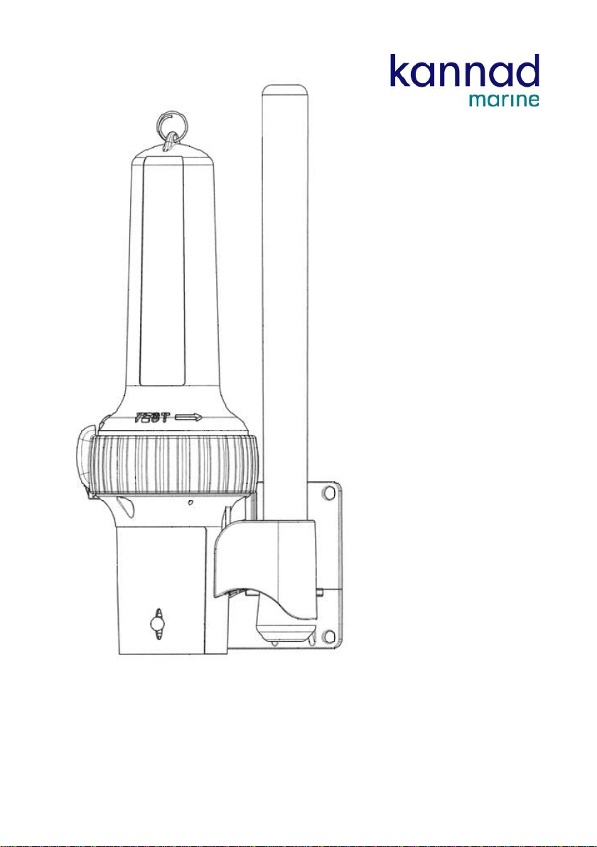
3. Installation
The preferred mounting location is inside the vessel, and protected from the elements,
usually on the ship’s bridge wing. The SART should be mounted where it will not get
in the way of day-to-day operations, but where it can readily be accessed near an
emergency exit in the event it is needed.
Do not install the SART within the ship's radar beam.
Fix the mounting bracket to a bulkhead in a convenient location. The recommended
fixing is by M5 marine grade stainless steel (e.g. A4/316) bolts; length is dependent
upon application. The bolts should be secured with either stainless steel locking nuts
or stainless steel nuts with stainless steel shake proof washers.
Mount the SART, dome uppermost, onto the bracket by locating the lugs on the SART
pole mount into the slots in the bracket. Push the SART down firmly into place.
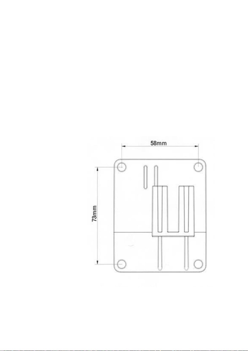
Figure 1
Bracket mounting holes: 4 holes, 5.5mm diameter
NOTE: Safe compass distance 1.5m.
Page
5
 Loading...