


9800 0332 01 a
845S
Date Code
0001L2001
GB

Service and Repair Manual
Model 845S
General
For best performance hammers should be serviced at regular intervals, any indication that the hammer is not performing as specified
should be investigated to prevent any adverse damage occuring.
ALL SEALS, GASKETS, GREASE OR OTHER PARTS DEEMED NECESSARY FOR SERVICING ARE IN THE SERVICE KIT.
ALL NEEDLE ROLLER BEARINGS SHOULD BE PRESSED WITH THE ROUNDED EDGE ENTERING THE BORE FIRST, AND THE PRESS TOOL
PRESSING AGAINST THE FLAT SURFACE OF THE BEARING.
Cleaning
All mechanical parts with the exception of any sealed bearings should be cleaned in a suitable cleaning fluid. Electrical parts should be
cleaned by the use of compressed air. PRECAUTIONS MUST BE TAKEN FOR PERSONAL SAFETY THE USE OF EYE PROTECTION AND
GLOVES IS RECOMMENDED.
Inspection
All mechanical and electric parts should be inspected for wear and replaced as required.
WARRANTY AND LIABILITY STATEMENT
2
Use only Authorized parts. Any damage or malfunction caused by the use of unauthorized parts
is not covered by Warranty or Product Liability.
SERVICE TOOLS
All repairs may be completed with standard workshop tools and equipment.
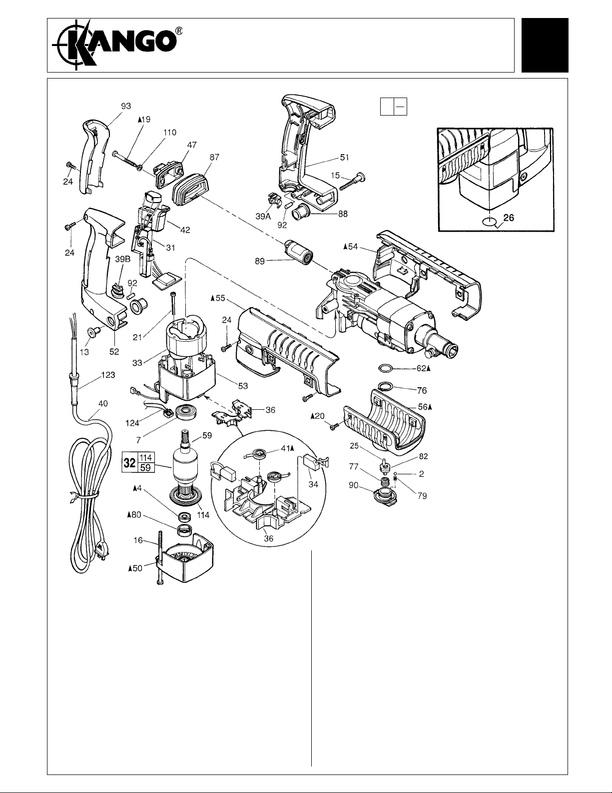
Service and Repair Manual
Model 845S
EXAMPLE:
Component Parts (Small #) Are Included
00
0
When Ordering The Assembly (Large #).
3
FIG. PART NO. DESCRIPTION OF PART NO. REQ.
2 9170 4667 30 5 mm Steel Ball (2)
4 9170 3251 20 Ball Bearing (1)
7 9170 3251 60 Ball Bearing (1)
13 9170 3253 10 Pivot Nut (1)
15 9170 3252 90 Pivot Bolt (1)
16 9170 3251 00 M6 x 1.0 x 120 Pan Hd. Slt. Tapt. T-27 (4)
19 9170 3253 90 Special Screw (2)
20 9170 3250 10 8-32 x 3/8" Pan Hd. Slt. Tapt. T-20 (4)
21 9170 3251 90 8-16 x 2" Pan Hd. Slt. Plast. T-20 (2)
24 9170 3252 50 M5 x 2.24 x 18 Pan Hd. Slt. PT T-20 (7)
25 9170 4650 10 Dowel Pin-Knurled (1)
26 9170 4652 70 Round Label (1)
31 9170 4650 60 Electronics Assembly (1)
32 9170 4650 80 120 Volt Armature (1)
33 9170 4651 70 120 Volt Field (1)
34 9170 3237 20 120 V Carbon Brush (2) Kit (1)
36 9170 3252 00 Brush Carrier Assembly (1)
39A 9170 3253 50 Lower Cord Clamp (1)
39B 9170 4665 60 Upper Cord Clamp (1)
40 9170 4651 90 Cord Set (1)
%SEE PAGE 5 FOR
ADDITIONAL LUBRICATION
AND SERVICE NOTES
FIG. PART NO. DESCRIPTION OF PART NO. REQ.
41 9170 3252 10 Brush Spring (2)
42 9170 4652 10 Speed Control Switch (1)
47 9170 3254 10 Upper Handle Mount (1)
50 9170 4652 30 Motor Cover (1)
51 9170 4656 80 Left Handle Half (1)
52 9170 4657 60 Right Handle Half (1)
53 9170 4658 40 Motor Housing (1)
54 9170 4659 40 Left Shroud (1)
55 9170 4659 50 Right Shroud (1)
56 9170 4659 90 Belly Shroud (1)
59 9170 3251 50 Retaining Ring (1)
62 9170 3250 80 O-Ring (1)
76 9170 3250 70 Retaining Ring (1)
77 9170 3250 50 Torsion Spring (1)
79 9170 3250 30 Compression Spring (2 )
80 9170 3251 10 Bearing Cup (1)
82 9170 4660 20 Shift Disk (1)
87 9170 3254 20 Isolation Bellows (1)
88 9170 3253 00 Pivot Isolator (2)
89 9170 3254 30 Isolation Module Assembly (1)
90 9170 3250 20 Rotostop Knob (1)
92 9170 3253 30 Foam Slug Kit (Bag of 10) (1)
93 9170 3252 60 Handle Cushion (1)
110 9170 3254 00 Rubber Washer (2)
114 9170 4660 90 Fan (1)
123 9170 3253 80 Cord Protector (1)
l

Service and Repair Manual
Model 845S
NOTE: USE OIL
ON ALL AREAS
TO BE PRESS FIT
Assemble Thrust Washers
#107 and Belleville Spring
Washers #78 into Intermediate
Housing #46 as illustrated.
4
FASTENER TORQUE SPECIFICATIONS (IN./LBS.)
FIG. NO. MINIMUM MAXIMUM
_______________________________________________________________
______________________________________________________________
________________________________________________________________
_______________________________________________________________
______________________________________________________________
______________________________________________________________
________________________________________________________________
___________________________________________
___________________________________________
14 120 140
15 20 25
16 30 35
19 30 35
20 25 30
21 20 25
22 25 30
23
CRANKCASE COVER
HANDLE HALVES
________________________________________
AND SHROUDS
24
CUSHION GRIP
105 60 70
9170 3237 20 CARBON BRUSH SERVICE KIT
2 --------------- Carbon Brush
SEATING TORQUE
25 30
20 25
610
THIS KIT CONTAINS:
l 9170 4660 00 HAMMER SERVICE KIT
THIS KIT CONTAINS:
1 9170 3254 50 Cap-Cover
1 9170 3261 00 Rubber Damping Washer
1 9170 3255 00 Seal-Cover
1 9170 4664 60 O-Ring
1 9170 3255 50 O-Ring
1 9170 4662 90 Cap Seal
1 9170 4664 40 O-Ring
1 9170 4665 50 O-Ring
1 9170 3251 10 Bearing Cup
1 9170 3261 40 Gasket
1 9170 4672 30 Dust Seal - Hex
1 9170 4672 40 Dust Seal - Round
1 9170 4672 50 7 Oz. Tube "S2" Grease
1 9170 3237 20 Carbon Brush Service Kit
%SEE PAGE 5
FOR ADDITIONAL
LUBRICATION
AND SERVICE NOTES

Service and Repair Manual
Model 845S
5
FIG. PART NO. DESCRIPTION OF PART NO. REQ.
1 9170 3256 50 1/8" Steel Ball (12)
3 9170 4661 10 1/4" Steel Ball (1)
5 9170 3254 90 Ball Bearing (1)
6 9170 3256 20 Ball Bearing (1)
8 9170 3257 20 Ball Bearing (1)
9 9170 3255 70 Needle Bearing (3)
10 9170 3255 20 Needle Bearing (1)
11 9170 3260 00 Needle Bearing (1)
12 9170 3260 30 Needle Bearing (1)
14 9170 4661 90 M6 x 1.0 x 70 Skt. Hd. Cap Scr. T-27 (4)
17 9170 4662 00 Cross Pin (1)
18 9170 3258 10 Dowel Pin (1)
22 9170 3254 60 8-32 x 3/8" Pan Hd. Slt. Taptite T-20 (1)
23 9170 3254 70 M4 x 0.7 x 14 Pan Hd. Slt. Taptite T-20 (4)
28 9170 3257 80 External Retaining Ring (1)
43 9170 3255 90 Bearing Retainer (1)
44 9170 4662 10 Crankcase (1)
45 9170 3254 40 Crankcase Cover (1)
46 9170 4662 30 Intermediate Housing (1)
48 9170 4662 50 Nose Assembly (1)
49 9170 3254 50 Cap-Cover (1)
57 9170 3257 30 Bevel Gear (1)
58 9170 4662 90 Cap Seal (1)
60 9170 4664 40 O-Ring (1)
61 9170 3255 80 O-Ring (1)
63 9170 3261 00 Rubber Damping Washer (1)
64 9170 3255 00 Seal-Cover (1)
65 9170 4664 60 O-Ring (1)
66 9170 3255 50 O-Ring (1)
67 9170 4665 50 O-Ring (1)
68 9170 3257 40 Retaining Ring (1)
69 9170 3254 80 Retaining Ring-Beveled (1)
70 9170 4665 70 Clutch Shaft (1)
71 9170 3257 10 Hollow Clutch Shaft (1)
72 9170 3255 60 Crankshaft Assembly (1)
73 9170 4666 20 Spindle (1)
74 9170 4666 80 Bit Lock Spring (1)
75 9170 3256 80 Compression Spring (1)
78 9170 3260 20 Belleville Spring (2)
81 9170 4667 40 Barrel (1)
83 9170 3256 90 Spring Flange (1)
84 9170 3261 40 Gasket (1)
91 9170 4667 50 Bit Lock (1)
94 9170 4661 60 Wrist Pin (1)
95 9170 4667 60 Piston (1)
96 9170 3256 70 Splined Clutch Plate (1)
97 9170 3256 60 Fixed Clutch Plate (1)
98 9170 4667 70 Ram (1)
99 9170 3256 40 Shift Ring (1)
100 9170 3255 10 Connecting Rod Assembly (1)
101 9170 4667 80 Dust Seal-Hex (5/pkg.) (1)
9170 4667 90 Dust Seal-Round (5/pkg.) (1)
102 9170 4663 00 Oil Seal (1)
104 9170 4668 00 Striker (1)
105 9170 4668 10 DG50 x 16mm Torx Pan Head Screw (4)
106 9170 4664 20 Felt Seal (1)
107 9170 3260 10 Thrust Washer (2)
108 9170 3261 10 Barrel Thrust Washer (1)
109 9170 3260 90 Striker Cushion Washer (1)
113 9170 3257 90 Wave Washer (1)
115 9170 4651 60 Hex Head Bolt-Special (1)
116 9170 4668 20 Side Handle Band (1)
117 9170 3257 70 Side Handle Assembly (1)
118 9170 4666 30 Depth Rod Mount Assembly (1)
119 9170 3257 60 Depth Gauge Rod (1)
120 9170 3258 20 Band Retainer (1)
121 9170 4668 40 Side Handle Housing (1)
9170 4668 50 Nose Service Tool
SERVICE CARRYING CASE
No. 9170 4667 20
l
l
l
l
l
l
l
l
l
l
l
LUBRICATION NOTES: (TYPE "S2" GREASE, NO. 9170 4664 70)
Fill Piston #95 with grease and
assemble to Connecting Rod #100
with Wrist Pin #94. Front surface
of Piston to be free of grease.
Lubricate O-Ring #67
with grease.
Place 1.5 oz. grease here.
in the barrel cavity in the crankcase #44.
Place
1.5 oz.
grease in bottom
of crankcase prior to
installing crankshaft
assembly.
Apply grease to
lobed surface #97.
Apply grease to radius
and spline surface #70.
Apply .5 oz. grease on
clutch assembly, filling the
spring coils.
Seal to be installed with
garter spring to left as shown.
.75+/-.015
Place a total of 1.0 oz. grease
Place .5 oz. in each corner in barrel
chamber.
FRONT OF CRANKCASE
Apply grease to spline
surface #71.
Apply grease to
lobed surface #96.
Dip Felt Washer #106 into light oil.
Press Oil Seal #102 and Felt Washer
into Nose #48 to dimension shown
using Nose Service Tool
9170 4668 50.
Lightly grease
Spring #74 and
bit lock #91.
Place .5 oz. grease in
lower clutch pinion cavity.
Lubricate O-Ring with grease.
Install O-Ring onto Ram.
Assemble Cap Seal onto Ram.
Resize Cap Seal and load into
Barrel (seal end first). Ram
should be located flush with
end of Barrel.

Service and Repair Manual
Model 845S
FIG. %NOTES
54, 55, 56 TO REMOVE BELLY SHROUD #56 FROM TOOL, INSERT SMALL SCREW
DRIVER INTO GROOVE BETWEEN BELLY AND SIDE SHROUDS #54 AND
#55, ABOUT 1/3 OF THE WAY FROM THE MOTOR END,
OUT AND DOWN ON BOTH SIDES OF THE TOOL.
54, 55 TO INSTALL THE SIDE SHROUDS #54 AND #55, THE TOP HINGE OF THE
SHROUDS MUST BE COMPLETELY INTERLOCKED, THEN THE BACK
SIDE ROTATED CLOSED AROUND THE TOOL.
73 LUBRICATE ALL BORES IN SPINDLE #73 WITH A MEDIUM COATING OF
GREASE.
63, 108, 109 LUBRICATE RUBBER DAMPING WASHER #63, BARREL THRUST
WASHER #108 AND STRIKER CUSHION WASHER #109 WITH A MEDIUM
COATING OF GREASE BEFORE ASSEMBLY.
10, 100 PRESS NEEDLE BEARING #10 IN ROD #100 SO THAT THE SAME
AMOUNT STICKS OUT ON BOTH SIDES OF THE ROD,
AS SHOWN. PRY
AS SHOWN.
6
9, 71 PRESS (2) NEEDLE BEARINGS #9 INTO HOLLOW CLUTCH SHAFT #71,
FLUSH WITH THE ENDS OF THE SHAFT.
11, 12, 46 PRESS NEEDLE BEARINGS #11 AND #12 FLUSH TO THE MACHINED
FACES ON BOTH ENDS OF THE INTERMEDIATE HOUSING #46.
9, 44 PRESS NEEDLE BEARING #9 INTO CRANKCASE #44, FLUSH WITH TOP
OF BORE,
81 LIGHTLY GREASE INSIDE OF BARREL #81 BEFORE ASSEMBLY.
48, 73 SMALL OUTSIDE DIAMETER OF SPINDLE #73 IS TO BELUBRICATED
WITH A LIGHT COAT OF GREASE BEFORE ASSEMBLING THE NOSE
ASSEMBLY #48 TO THE TOOL.
48, 73, 102 NOSE ASSEMBLY #48 MUST BE PLACED SQUARELY OVER SPINDLE #73,
WHEN ASSEMBLING, TO PREVENT DAMAGE TO OIL SEAL #102.
14, 19, 20, 23 FASTENERS #14, #19, #20 AND #23 ARE TO BE RE-ASSEMBLED USING
BLUE LOCTITE.
48, 102 LUBRICATE BORE IN NOSE ASSEMBLY #48 BEFORE PRESSING OIL
SEAL #102 INTO PLACE.
60, 61, 62, LUBRICATE O-RINGS #60, #61, #62, #66 AND #67 WITH GREASE.
66, 67
69 INSTALL BEVEL SNAP RING #69 WITH BEVEL SIDE UP.
AS SHOWN.
4, 50, 80 PLACE BEARING CUP #80 ON SMALL ARMATURE BEARING #4 BEFORE
INSTALLING MOTOR COVER #50.
41 BRUSH SPRINGS #41 ARE TO BE WOUND 1/2 TURN TO ENGAGE
BRUSHES.
4 RUBBER SEAL SIDE OF BALL BEARING #4 TO FACE FAN.
95, 98 FACES OF PISTON #95 AND RAM #98 ARE TO BE FREE OF GREASE.
105 WHEN REASSEMBLING BARREL AND CLUTCH SCREWS INTO EXISTING
CRANKCASE, MAKE SURE SCREW IS STARTED IN EXISTING THREAD.
DO NOT CREATE TWO SETS OF THREADS IN ONE HOLE.

As an aid to reassembly, take note of wire routing and
position in wire guides and traps while dismantling tool.
Tuck all wiring into left handle half
prior to assembling right handle half.
This will avoid pinched wires.
Service and Repair Manual
Model 845S
7
SWITCH
CONNECTIONS
(Bottom view)
Fast-on
terminals must be
completely connected
between leads 4 and 9.
Wrap
wire tie around
electronics boat
to retain leads as
shown.
Cord to
be inserted into clamp
trap. Cord to extend 1/4"
minimum above top of
clamp. (For 120 V only.
See below for 110 V
and 230 V.)
Keep leads
away from
potential
pinch points.
Brush to
brush plate
connections.
Brush
springs
must be seated
in slot located on
brush tubes.
BRUSH CARD
ASSEMBLY
Brush shunt wires to
be positioned up in
brush tube slots, as
shown, for full travel.
Check that there is
clearance between the
fan and brush shunt
wires.
Tuck leads
5 and 6
away from
armature.
WIRING SPECIFICATIONS
Wire Origin or
No. 110 V 120 V 230 V Part No. Connection
1 Blue White Blue Cord Switch
2 Bro wn Black B ro wn Cord Switch
3 Red Red Red Field Lead 9
4 Red Red Red Field Switch
5 Yel low Yellow Ye llow Field Brush Holder
6 Black Black Black Field Brush Holder
7 White White White Motor Control Assy. Switch
8 Black Black Black Motor Control Assy. Switch
9 Black Blue Red Motor Control Assy. Lead 3
Wire Color
110 V and 230 V
QUIK-LOK CORD
ORIENTATION
Electronics Assembly
Inductor Boat
WIRING
SCHEMATIC

Service and Repair Manual
Model 845S
ELECTRICAL TESTING
Electrical test
Before assemby all electrical parts MUST be checked for safety, and that they conform to specification.
Testing the Armature (Flash Testing)
A Armature shaft to lamination pack 1500 Volts (min)
B Lamination pack to commutator 1200 Volts (min)
C Armatuure shaft to commutator 3000 Volts (min)
8
ELECTRICAL PERFORMANCE TEST READINGS
ARMATURES
MODEL
845S
845S
845S
Measured on disassembly/assembly 35/45ft lbs 47/61Nm. (Non Electrical Test)
Note: On all test readings + or -5% of figures shown is acceptable.
.440/.506 Ohms .440/.506 Ohms 1.283/1.477 Ohms
.349/.401 Ohms .349/.401 Ohms 1.339/1.54 Ohms
4.5/6.5 Amps 4.5/6.5 Amps 2.9/4.4 Amps
110V 120V 220V-240V
FIELD COILS
110V 120V 220V-240V
PERFORMANCE
Running No Load
110V 120V 220V-240V
CLUTCH SLIP

Service and Repair Manual
Model 845S
WARNING
LETHAL VOLTAGES PRESENT!!
IMPORTANT
On completion of the assembly, the unit must be flash tested at 4000 volts.
Flash Test
1. With the breaker completely assembled and with the switch "ON", apply 2000 volts initially and increase rapidly to 4000 volts between the
main casting and one of the pins of the plug on the power supply cord. Apply test to both live and neutral pins.
2. The full voltage of 4000 volts should be maintained without breakdown or flashover for a few seconds.
3. If the armature has been tested, remove the carbon brushes before carrying out the test, (thus avoiding overstressing the armature
insulation system).
4. The test voltage must be applied between the main casting and each live pin of the plug in succession.
Running Test
1. Ensure the unit is switched "ON" before testing. Operate the unit for approx. 10 minutes at half voltage for initial 'bedding in' of the carbon
brushes followed by full operational voltage. Compare readings with Performance Data.
9
FAULT FINDING
With the aid of the Fault Finding chart (below) the source of any malfunction may be quickly identified and repaired.

Atlas Copco Berema AB, Sickla Industriväg 1A, S-105 23
Nacka Sweden
9800 0332 01 a
54-24-0975 Drwg. 3 04/02
Telephone: +46 (0) 8 743 9600 Fax: +46 (0) 8 743 9650
 Loading...