


OPERATOR'S MANUAL
MANUEL DE L'UTILISATEUR
MANUAL DEL OPERADOR
ROTARY & CHIPPING HAMMERS
MARTEAUX ROTATIFS & PERFORATEURS
MARTILLOS ROTATORIO & PARA PICADO
Catalog No.
No de Cat.
Número de Catálogo
800S
845S
TO REDUCE THE RISK OF INJURY, USER MUST READ AND UNDERSTAND OPERATOR'S MANUAL.
AFIN DE RÉDUIRE LE RISQUE DE BLESSURES, L'UTILISATEUR DOIT LIRE ET BIEN COMPRENDRE LE
MANUEL DE L'UTILISATEUR.
PARA REDUCIR EL RIESGO DE LESIONES, EL USUARIO DEBE LEER Y ENTENDER EL MANUAL DEL
OPERADOR.
© Copyright 2000 ATLAS COPCO BEREMA AB
STOCKHOLM • SWEDEN
No. 9800 7126 93
2000-12
GENERAL SAFETY RULES
WARNING!
READ AND UNDERSTAND ALL INSTRUCTIONS
Failure to follow all instructions listed below, may result in
electric shock, fire and/or serious personal injury.
SAVE THESE INSTRUCTIONS
WORK AREA
1. Keep your work area clean and well lit. Cluttered benches and
dark areas invite accidents.
2. Do not operate power tools in explosive atmospheres, such
as in the presence of flammable liquids, gases, or dust.
Power tools create sparks which may ignite the dust or fumes.
3. Keep bystanders, children, and visitors away while operat-
ing a power tool. Distractions can cause you to lose control.
Protect others in the work area from debris such as chips and
sparks. Provide barriers or shields as needed.
ELECTRICAL SAFETY
4. Grounded tools must be plugged into an outlet properly
installed and grounded in accordance with all codes and
ordinances. Never remove the grounding prong or modify
the plug in any way. Do not use any adaptor plugs. Check
with a qualified electrician if you are in doubt as to whether
the outlet is properly grounded. If the tools should electrically
malfunction or break down, grounding provides a low resistance
path to carry electricity away from the user.
5. Double Insulated tools are equipped with a polarized plug
(one blade is wider than the other). This plug will fit in a
polarized outlet only one way. If the plug does not fit fully in
the outlet, reverse the plug. If it still does not fit, contact a
qualified electrician to install a polarized outlet. Do not change
the plug in any way. Double insulation eliminates the need for
the three wire grounded power cord and grounded power supply
system.
6. Avoid body contact with grounded surfaces such as pipes,
radiators, ranges and refrigerators. There is an increased risk
of electric shock if your body is grounded.
7. Do not expose power tools to rain or wet conditions. Water
entering a power tool will increase the risk of electric shock.
8. Do not abuse the cord. Never use the cord to carry the tools
or pull the plug from an outlet. Keep cord away from heat,
oil, sharp edges or moving parts. Replace damaged cords
immediately. Damaged cords increase the risk of electric shock.
9. When operating a power tool outside, use an outdoor
extension cord marked “W-A” or “W”. These cords are rated
for outdoor use and reduce the risk of electric shock.
PERSONAL SAFETY
10. Stay alert, watch what you are doing, and use common sense
when operating a power tool. Do not use tool while tired or
under the influence of drugs, alcohol, or medication. A
moment of inattention while operating power tools may result in
serious personal injury.
11. Dress properly. Do not wear loose clothing or jewelry.
Contain long hair. Keep your hair, clothing, and gloves away
from moving parts. Loose clothes, jewelry, or long hair can be
caught in moving parts.
12. Avoid accidental starting. Be sure switch is off before
plugging in. Carrying tools with your finger on the switch or
plugging in tools with the switch on invites accidents.
13. Remove adjusting keys or wrenches before turning the
tool on. A wrench or a key that is left attached to a rotating part of
the tool may result in personal injury.
14. Do not overreach. Keep proper footing and balance at all
times. Proper footing and balance enables better control of the tool
in unexpected situations.
15. Use safety equipment. Always wear eye protection. Dust
mask, non-skid safety shoes, hard hat, or hearing protection must
be used for appropriate conditions.
TOOL USE AND CARE
16. Use clamps or other practical way to secure and support
the workpiece to a stable platform. Holding the work by hand
or against your body is unstable and may lead to loss of control.
17. Do not force tool. Use the correct tool for your application.
The correct tool will do the job better and safer at the rate for which
it is designed.
18. Do not use tool if switch does not turn it on or off. Any tool
that cannot be controlled with the switch is dangerous and must be
repaired.
19. Disconnect the plug from the power source before making
any adjustments, changing accessories, or storing the tool.
Such preventive safety measures reduce the risk of starting the tool
accidentally.
20. Store idle tools out of reach of children and other untrained
persons. Tools are dangerous in the hands of untrained users.
21. Maintain tools with care. Keep cutting tools sharp and clean.
Properly maintained tools with sharp cutting edge are less likely to
bind and are easier to control. Do not use a damaged tool. Tag
damaged tools “Do not use” until repaired.
22. Check for misalignment or binding of moving parts, break-
age of parts, and any other condition that may affect the
tool’s operation. If damaged, have the tool serviced before
using. Many accidents are caused by poorly maintained tools.
23. Use only accessories that are recommended by the manufacturer for your model. Accessories that may be suitable for
one tool, may become hazardous when used on another tool.
SERVICE
24. Tool service must be performed only by qualified repair
personnel. Service or maintenance performed by unqualified per-
sonnel could result in a risk of injury.
25. When servicing a tool, use only identical replacement parts.
Follow instructions in the Maintenance section of this
manual. Use of unauthorized parts or failure to follow Maintenance
Instructions may create a risk of electric shock or injury.
page 2

SPECIFIC SAFETY RULES
1. Hold tool by insulated gripping surfaces when performing an operation where the cutting tool may contact hidden wiring or its
own cord. Contact with a "live" wire will make exposed metal parts of the tool "live" and shock the operator.
2. Wear ear protectors when using the tool for extended periods. Prolonged exposure to high intensity noise can cause hearing loss.
3. Keep hands away from all cutting edges and moving parts.
4. Maintain labels and nameplates. These carry important information. If unreadable or missing, contact a
replacement.
5. WARNING! Some dust created by power sanding, sawing, grinding, drilling, and other construction activities contains chemicals known to cause
cancer, birth defects or other reproductive harm. Some examples of these chemicals are:
• lead from lead-based paint
• crystalline silica from bricks and cement and other masonry products, and
• arsenic and chromium from chemically-treated lumber.
Your risk from these exposures varies, depending on how often you do this type of work. To reduce your exposure to these chemicals: work in
a well ventilated area, and work with approved safety equipment, such as those dust masks that are specially designed to filter out microscopic
particles.
Service Agent facility for a free
Symbology
To reduce the risk of injury, user
must read and understand
operator's manual
Double Insulated
Canadian Standards Association
Underwriters Laboratories, Inc.
Volts Alternating Current
No Load Revolutions per
Minute (RPM)
Amperes
Hertz
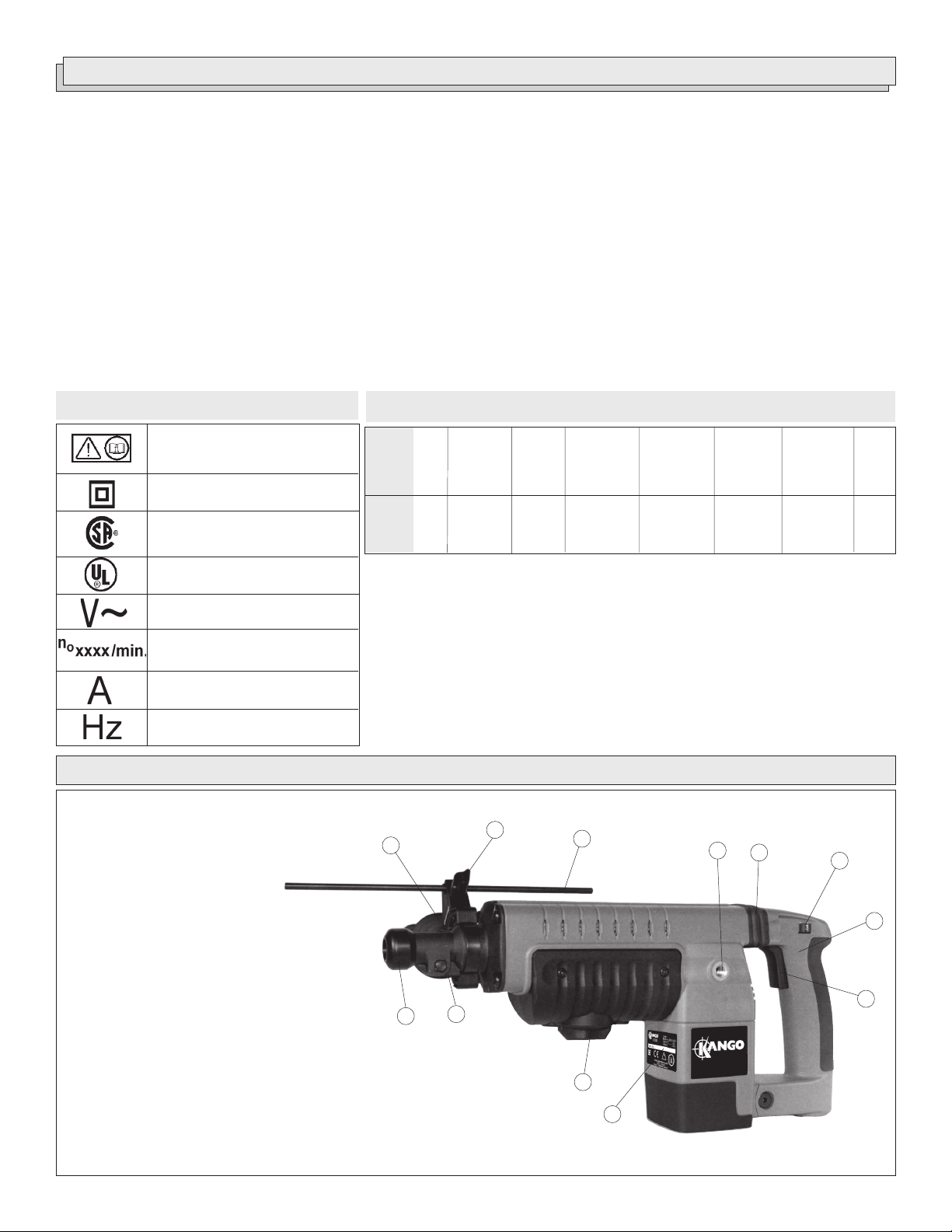
1. Rear side handle mount
2. Vibration Isolation System
3. Speed control dial
4. Handle
5. Trigger
6. Nameplate
7. Stop rotation knob (Cat. No. 845S)
8. Bit lock
9. Dust shield
10. Vibration isolation side handle
11. Depth gauge adjustment knob (Cat. No. 845S)
12. Depth gauge (Cat. No. 845S)
Specifications
13.0
13.0
Load/
No
Load
RPM
--
150-400*
Volts
Cat.
AC
No.
Only
Amps
800S
120
845S
120
*
EFCC - The Electronic Feedback Control Circuit maintains constant speed under
varying load conditions.
Load/
No Load
Blows per
Minute
1300-3450*
1300-3450*
Percussion
Carbide
Tipped
Bits
--
1-3/4"
Percussion
Core
Bits
--
6"
Self-
Drilling
Anchors
--
5/8"
FUNCTIONAL DESCRIPTION
10
11
9
8
12
1
2
7
6
Chisels
Round/
Hex
See p.8
3
5
4
Cat. No. 845S
page 3

GROUNDING EXTENSION CORDS
WARNING!
Improperly connecting the grounding wire can
result in the risk of electric shock. Check with a
qualified electrician if you are in doubt as to
whether the outlet is properly grounded. Do not
modify the plug provided with the tool. Never
remove the grounding prong from the plug. Do
not use the tool if the cord or plug is damaged. If
damaged, have it repaired by a service agent
before use. If the plug will not fit the outlet, have
a proper outlet installed by a qualified electrician.
Grounded Tools:
Tools with Three Prong Plugs
Tools marked “Grounding Required”
have a three wire cord and three
prong grounding plug. The plug must
be connected to a properly grounded
outlet (See Figure A). If the tool should
electrically malfunction or break
down, grounding provides a low resistance path to carry electricity
away from the user, reducing the risk
of electric shock.
The grounding prong in the plug is connected through the green wire
inside the cord to the grounding system in the tool. The green wire in the
cord must be the only wire connected to the tool's grounding system and
must never be attached to an electrically “live” terminal.
Your tool must be plugged into an appropriate outlet, properly installed
and grounded in accordance with all codes and ordinances. The plug
and outlet should look like those in Figure A.
Double Insulated Tools:
Tools with Two Prong Plugs
Tools marked “Double Insulated” do
not require grounding. They have a
special double insulation system
which satisfies OSHA requirements
and complies with the applicable
standards of Underwriters Laboratories, Inc., the Canadian Standard
Association and the National Electrical Code. Double Insulated tools may
be used in either of the 120 volt outlets shown in Figures B and C.
Fig. A
Fig. B
Fig. C
Grounded tools require a three wire extension cord. Double insulated
tools can use either a two or three wire extension cord. As the distance
from the supply outlet increases, you must use a heavier gauge extension cord. Using extension cords with inadequately sized wire causes a
serious drop in voltage, resulting in loss of power and possible tool
damage. Refer to the table shown to determine the required minimum
wire size.
The smaller the gauge number of the wire, the greater the capacity of the
cord. For example, a 14 gauge cord can carry a higher current than a 16
gauge cord. When using more than one extension cord to make up the
total length, be sure each cord contains at least the minimum wire size
required. If you are using one extension cord for more than one tool, add
the nameplate amperes and use the sum to determine the required minimum wire size.
Guidelines for Using Extension Cords
• If you are using an extension cord outdoors, be sure it is marked
with the suffix “W-A” (“W” in Canada) to indicate that it is acceptable
for outdoor use.
• Be sure your extension cord is properly wired and in good electrical
condition. Always replace a damaged extension cord or have it
repaired by a qualified person before using it.
• Protect your extension cords from sharp objects, excessive heat
and damp or wet areas.
Recommended Minimum Wire Gauge
Nameplate
Amperes
12.1 - 15
15.1 - 20
* Based on limiting the line voltage drop to five
volts at 150% of the rated amperes.
for Extension Cords*
25'
0 - 5
5.1 - 8
8.1 - 12
16
16
14
12
10
Extension Cord Length
100'
14
12
10
10
150'
12
10
--
--
--
--
50'
16
16
14
12
10
75'
16
14
12
10
10
200'
12
--
--
--
--
READ AND SAVE ALL INSTRUCTIONS FOR
FUTURE USE.
page 4

TOOL ASSEMBLY
WARNING!
To reduce the risk of injury, always unplug
tool before attaching or removing accessories
or making adjustments. Use only specifically
recommended accessories. Others may be
hazardous.
Adjusting the Side Handle (Fig. 1)
Fig. 1
1. Loosen the side handle slightly by unscrewing it counterclockwise.
2. Rotate the side handle to the required angle.
3. Tighten the side handle securely.
1
1. Insert the chisel into the nose of the tool. Make sure that the notch in
the shank faces toward the bit lock.
2. To lock, push the bit lock to the right as shown.
3. To unlock, push the bit lock to the left as shown.
NOTE: Use caution when handling hot bits and chisels.
Installing Bits and Chisels (Fig. 3)
Spline Drive System (Cat. No. 845S)
The 845S Rotary Hammer uses carbide bits with spline shanks and
hammer steel chisels with round hex shanks.
Fig. 3
Rotary bit with spline shank
WARNING!
To reduce the risk of injury, always use a side
handle when using this tool. Always brace and
hold securely.
The side handle can be used at the rear of the tool. Remove the handle
and install it in one of the positions provided on either side (1). Use the
side handle knob in the front handle position to secure the depth gauge
assembly (Cat. No. 845S only).
Installing Chisels (Fig. 2)
Round Hex System (Cat. No. 800S)
The 800S Chipping Hammer uses hammer steel chisels with round hex
shanks.
Fig. 2
Chisel with round hex shank
1. Insert the bit or chisel into the nose of the tool.
If you are using a rotary bit, make sure that the splines on the shank
engage with the splines inside the nose of the tool.
If you are using a chisel, make sure that the notch in the shank faces
toward the bit lock.
2. To lock, push the bit lock to the right as shown.
3. To unlock, push the bit lock to the left as shown.
NOTE: Use caution when handling hot bits and chisels.
Setting the Depth Gauge (Fig. 4)
(Cat. No. 845S)
Fig. 4
1
2
Chisel with round hex shank
1. Loosen the depth gauge adjustment knob (2).
2. Slide the depth gauge rod (1) backward or forward until it is set for
the desired depth. The drilling depth is the distance between the tip
of the bit and the tip of the depth gauge rod.
3. Tighten the depth gauge adjustment knob securely.
page 5

OPERATION
These hammers have an Electronic Feedback Control Circuit (EFCC)
which helps improve the operation and life of the tool.
Soft Start
The Soft-Start feature reduces the amount of torque reaction to the tool
and the user. This feature gradually increases the motor speed up from
zero to the speed set by the speed control dial.
Feedback Control
The electronic speed control system allows the tool to maintain constant
speed and torque between no-load and load conditions.
WARNING!
To reduce the risk of injury, wear safety goggles
or glasses with side shields.
Selecting Action (Fig. 5)
(Cat. No. 845S)
The stop rotation knob may be set for either “hammering-only” or
“hammering-with-rotation”.
Fig. 5
1
Hammering Only
Spline Drive System (Cat. No. 845S)
When a chisel (or other “hammering-only” accessory) is mounted into
the 845S Rotary Hammer and the stop rotation knob is set for “hammering-with-rotation”, the rotational drive mechanism does not engage with
the chisel, even though the rotational drive mechanism is running. The
845S can use chisels in the “hammering-with-rotation” setting or the
“hammering-only” setting.
Selecting Speed
These hammers have a speed control dial. For the 800S, the speed
control dial allows the user to adjust the impact rate (BPM) of the tool. For
the 845S, the speed control dial allows the user to adjust the rotating
speed (RPM) and the impact rate (BPM) of the tool.
To change the speed, set the speed control dial to the desired setting.
Lower speeds provide more control when starting holes and reduce
‘spalling’ on breakthrough. Spalling occurs when pieces of material chip
off around the drilled hole on breakthrough. When chiseling in soft or
brittle materials, use lower speeds to reduce damage to surrounding
areas of the material.
Higher speeds provide for faster penetration when drilling and chiseling
in demolition work.
Starting and Stopping the Tool
1. To start the tool, pull trigger.
2. To stop the tool, release trigger.
2
1. Hammering only. For use with “hammering-only” accessories.
Use this setting (1) for chiseling or setting self-drilling anchors.
2. Hammering with rotation. Use this setting (2) for drilling holes
with drill bits.
NOTE: To engage the hammering mechanism, maintain pressure on the
bit. When the pressure on the bit is released, the hammering will stop.
Cold Starting
If this tool is stored for a long period of time or at cold temperatures, it
may not hammer initially because the lubrication has become stiff.
To warm up the tool:
1. Insert and lock a bit or chisel into the tool.
2. Turn the tool on, applying force to the bit or chisel against a concrete
or wood surface.
3. Turn the tool on and off every few seconds. In a short time, the tool
will start hammering. The colder the tool is, the longer it will take to
warm it up.
page 6

WARNING!
Applying greater pressure does not increase the tool's
effectiveness. If the applied working pressure is too
high, the shock absorber will be pushed together
making the vibrations to the handle noticeably
stronger.
Fig. 7
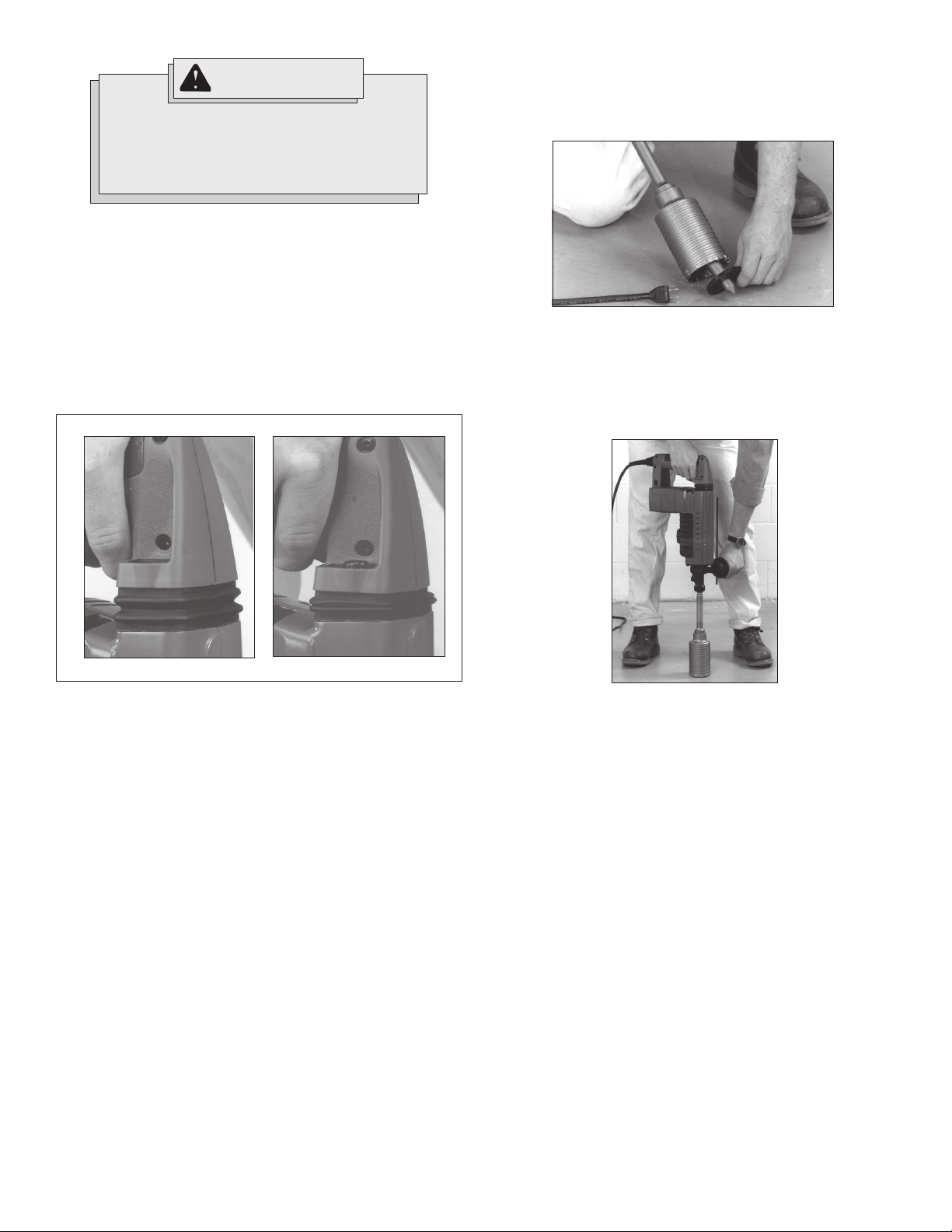
Operator Force (Fig. 6)
These hammers feature the Vibration Isolation System to provide the
operator with comfort without sacrificing power or performance. The
motor is suspended independently from the switch handle.
Insulating elements absorb up to 50% of the vibration when hammering
and drilling.
Ideal operator force compresses the bellows slightly and allows the tool
to work aggressively while the handle remains steady.
Excessive force compresses the bellows significantly and reduces vibration dampening. Users will be able to feel the difference and should
adjust the force to the handle accordingly (Fig. 6).
Fig. 6
ideal applied force
excessive applied force
3. Insert the adapter into the nose of the tool as described in “Installing
Bits”. Set the stop rotation knob to the hammering-with-rotation
setting.
4. Press the center pin firmly against your center mark, hold the tool
firmly and pull the trigger (Fig. 8).
Fig. 8
NOTE: If a center pin and guide plate are not available, use a template or
notched board to start the hole (Fig. 9).
Fig. 9
The side handle works in a similar fashion, where moderate operator
force dampens vibration and excessive force reduces this effect.
Hammering or Hammering with Rotation
Position the tool, grasp the handles firmly and pull the trigger.
Always hold the tool securely using both handles and maintain control.
Use only enough pressure to hold the tool in place and prevent the tip of
the bit from wandering. This tool has been designed to achieve top
performance with only moderate pressure. Let the tool do the work.
For 845S- if the speed begins to drop off when drilling deep holes, pull
the bit partially out of the hole while the tool is running to help clear dust.
NOTE: Do not use water to settle the dust since it will clog the bit flutes
and tend to make the bit bind in the hole. If the bit should bind, a built-in,
non-adjustable slip clutch prevents the bit from turning. If this occurs,
stop the tool, free the bit and begin again.
Using Rotary Percussion Core Bits (Fig. 7 - 10)
(Cat. No. 845S)
Core bits are useful for drilling large holes for conduit and pipe.
Core bits have heat-treated steel bodies with durable carbide tips. These
core bits are specially designed for fast, accurate drilling with combined
hammering and rotary action.
1. Clean and lubricate the threads on the adapter and core bit to make
later removal easier. Screw the threaded end of the adapter into the
rear of the core bit.
2. Push the guide plate onto the pointed end of the center pin. Insert the
center pin and guide plate assembly into the core bit. Be sure the
small end of the center pin is securely placed into the hole in the
center of the core bit (Fig. 7).
5. After drilling to about the depth of the core bit teeth, remove the
center pin and guide plate from the core bit. Resume drilling.
6. To change the core bit, hold the tool upwards, pointing it away from
your body as shown, and run it briefly in forward to loosen the core
bit from the adapter (Fig. 10).
Fig. 10
NOTE: To make deeper holes, remove the core bit, break and remove the
core. Resume drilling.
page 7

WARNING!
To reduce the risk of personal injury and damage to the
tool or work:
• Always use the “hammering-only” setting to set
the anchor. Never use the “hammering-withrotation” setting to set the anchor.
• Never switch the tool to “hammering-with-rotation”
until after the anchor has been set and the tooth
anchor chuck has been removed from the anchor.
Setting Self-Drilling Anchors (Fig. 11 - 16)
(Cat. No. 845S)
The 845S Rotary Hammer features a stop rotation knob which is helpful
for setting self-drilling anchors up to 5/8". Tooth anchor chucks require a
“B” taper adapter.
Fig. 11
Fig. 12
1/8"
1. Place the proper size tooth anchor chuck into the “B” taper adapter.
Then insert the “B” taper adapter into the tool and lock it into place as
described. See “Installing Bits and Chisels”.
2. Insert the anchor into the tooth anchor chuck. Set the stop rotation
knob for hammering only. Set the anchor on your mark and hammer
until the teeth have penetrated the concrete (Fig. 11).
3. Switch the stop rotation knob for hammering with rotation and drill
until the chuck is 1/8" above the concrete (Fig. 12).
NOTE: It may be necessary to clean dust and cuttings from the
anchor several times while drilling the hole.
4. Remove the anchor from the hole while the tool is running. Clean the
dust and cuttings from the anchor by pointing it downward and
turning the tool on and off several times. Clean the dust out of the
hole with a vacuum cleaner or blowout bulb (Fig. 13).
5. Place the expansion plug into the anchor and insert the anchor into
the hole. Switch the stop rotation knob back to hammering only, and
hammer the anchor firmly into the hole (Fig. 14).
6. Snap the head off of the anchor. To remove the head of anchors up
to 5/8", grasp the handles firmly and pull the tool sharply towards
you (Fig. 15) or snap off the anchor head with a hand hammer as
shown (Fig. 16). The anchor is now ready to receive a bolt.
7. To remove the anchor head wedged in the tooth anchor chuck, use
ejector No. 9170 0888 40.
8. To remove the tooth anchor chuck, remove the “B” taper adapter
from the nose of the tool. Insert the drift pin supplied with the adapter
into the hole on the side of the “B” taper adapter and strike it sharply
to force out the tooth anchor chuck.
Fig. 13
Fig. 14
Fig. 15
Fig. 16
Chiseling and Chipping
These hammers may be used for chipping and chiseling.
When chiseling, hold the tool at an angle to the workpiece. Work from a
corner or close to the edge of the workpiece, breaking off one small area
at a time rather than attempting too large an area.
A variety of accessories are available:
Bushing Tools
Used to surface concrete.
Mortar Cutting Chisels (Seam Tools)
For removing old mortar for tuck pointing or
caulking.
Bull Points
For demolition work and starting holes in concrete slabs.
Flat Chisels
For edging, chipping or channeling.
Scaling Chisels
For removing weld spatter or scale and cutting
straight lines.
page 8
Slotting Chisel
For slotting and cutting between drilled holes
in concrete and masonry.

MAINTENANCE
WARNING!
To reduce the risk of injury, always unplug your
tool before performing any maintenance. Never
disassemble the tool or try to do any rewiring on
the tool's electrical system. Contact a
Service Agent for ALL repairs.
Maintaining Tools
Keep your tool in good repair by adopting a regular maintenance program. Before use, examine the general condition of your tool. Inspect
guards, switches, tool cord set and extension cord for damage. Check
for loose screws, misalignment, binding of moving parts, improper mounting, broken parts and any other condition that may affect its safe operation. If abnormal noise or vibration occurs, turn the tool off immediately
and have the problem corrected before further use. Do not use a damaged tool. Tag damaged tools “DO NOT USE” until repaired
(see “Repairs”).
Under normal conditions, relubrication is not necessary until the motor
brushes need to be replaced. After six months to one year, depending on
use, return your tool to the nearest service agent for the following:
• Lubrication
• Brush inspection and replacement
• Mechanical inspection and cleaning (gears, spindles, bearings,
housing, etc.)
• Electrical inspection (switch, cord, armature, etc.)
• Testing to assure proper mechanical and electrical operation
WARNING!
To reduce the risk of injury, electric shock and
damage to the tool, never immerse your tool in
liquid or allow a liquid to flow inside the tool.
Cleaning
Clean dust and debris from vents. Keep the tool handles clean, dry and
free of oil or grease. Use only mild soap and a damp cloth to clean your
tool since certain cleaning agents and solvents are harmful to plastics
and other insulated parts. Some of these include: gasoline, turpentine,
lacquer thinner, paint thinner, chlorinated cleaning solvents, ammonia
and household detergents containing ammonia. Never use flammable or
combustible solvents around tools.
Repairs
If your tool is damaged, return the entire tool to the nearest service
center listed on the back cover of this operator’s manual.
ACCESSORIES
For a complete listing of accessories refer to your Accessory catalog.
To obtain a catalog, refer to your Service Agent List for the Service
Agent nearest you.
page 9

RÈGLES DE SÉCURITÉ GÉNÉRALES
AVERTISSEMENT!
VOUS DEVEZ LIRE ET COMPRENDRE TOUTES LES INSTRUCTIONS
Le non-respect, même partiel, des instructions ci-après entraîne un risque de choc
électrique, d'incendie et/ou de blessures graves.
CONSERVEZ CES INSTRUCTIONS
AIRE DE TRAVAIL
1. Veillez à ce que l’aire de travail soit propre et bien éclairée.
Le désordre et le manque de lumière favorisent les accidents.
2. N’utilisez pas d’outils électriques dans une atmosphère ex-
plosive, par exemple en présence de liquides, de gaz ou de
poussières inflammables. Les outils électriques créent des
étincelles qui pourraient enflammer les poussières ou les vapeurs.
3. Tenez à distance les curieux, les enfants et les visiteurs
pendant que vous travaillez avec un outil électrique. Ils
pourraient vous distraire et vous faire faire une fausse manoeuvre.
Installez des barrières ou des écrans protecteurs si nécessaire.
SÉCURITÉ ÉLECTRIQUE
4. Les outils mis à la terre doivent être branchés dans une
prise de courant correctement installée et mise à la terre
conformément à tous les codes et règlements pertinents.
Ne modifiez jamais la fiche de quelque façon que ce soit,
par exemple en enlevant la broche de mise à la terre.
N’utilisez pas d’adaptateur de fiche. Si vous n’êtes pas
certain que la prise de courant est correctement mise à la
terre, adressez-vous à un électricien qualifié. En cas de
défaillance ou de défectuosité électrique de l’outil, une mise à la
terre offre un trajet de faible résistance à l’électricité qui autrement
risquerait de traverser l’utilisateur.
5. Les outils à double isolation sont équipés d’une fiche
polarisée (une des lames est plus large que l’autre), qui ne
peut se brancher que d’une seule façon dans une prise
polarisée. Si la fiche n’entre pas parfaitement dans la prise,
inversez sa position ; si elle n’entre toujours pas bien,
demandez à un électricien qualifié d’installer une prise de
courant polarisée. Ne modifiez pas la fiche de l’outil.
La double isolation élimine le besoin d’un cordon d’alimentation à
trois fils avec mise à la terre ainsi que d’une prise de courant mise à
la terre.
6. Évitez tout contact corporel avec des surfaces mises à la
terre (tuyauterie, radiateurs, cuisinières, réfrigérateurs,
etc.). Le risque de choc électrique est plus grand si votre corps est
en contact avec la terre.
7. N’exposez pas les outils électriques à la pluie ou à l’eau. La
présence d’eau dans un outil électrique augmente le risque de choc
électrique.
8. Ne maltraitez pas le cordon. Ne transportez pas l’outil par
son cordon et ne débranchez pas la fiche en tirant sur le
cordon. N’exposez pas le cordon à la chaleur, à des huiles, à
des arêtes vives ou à des pièces en mouvement. Remplacez
immédiate-ment un cordon endommagé. Un cordon
endommagé augmente le risque de choc électrique.
9. Lorsque vous utilisez un outil électrique à l’extérieur,
employez un prolongateur pour l’extérieur marqué « W-A »
ou « W ». Ces cordons sont faits pour être utilisés à l’extérieur et
réduisent le risque de choc électrique.
SÉCURITÉ DES PERSONNES
en mouvement. Des vêtements flottants, des bijoux ou des
cheveux longs risquent d’être happés par des pièces en mouvement.
12. Méfiez-vous d’un démarrage accidentel. Avant de brancher
l’outil, assurez-vous que son interrupteur est sur ARRÊT. Le
fait de transporter un outil avec le doigt sur la détente ou de brancher
un outil dont l’interrupteur est en position MARCHE peut mener tout
droit à un accident.
13. Enlevez les clés de réglage ou de serrage avant de démarrer
l’outil. Une clé laissée dans une pièce tournante de l’outil peut
provoquer des blessures.
14. Ne vous penchez pas trop en avant. Maintenez un bon appui
et restez en équilibre en tout temps. Un bonne stabilité vous
permet de mieux réagir à une situation inattendue.
15. Utilisez des accessoires de sécurité. Portez toujours des
lunettes ou une visière. Selon les conditions, portez aussi un
masque antipoussière, des bottes de sécurité antidérapantes, un
casque protecteur et/ou un appareil antibruit.
UTILISATION ET ENTRETIEN DES OUTILS
16. Immobilisez le matériau sur une surface stable au moyen
de brides ou de toute autre façon adéquate. Le fait de tenir la
pièce avec la main ou contre votre corps offre une stabilité
insuffisante et peut amener un dérapage de l’outil.
17. Ne forcez pas l’outil. Utilisez l’outil approprié à la tâche. L’outil
correct fonctionne mieux et de façon plus sécuritaire. Respectez
aussi la vitesse de travail qui lui est propre.
18. N’utilisez pas un outil si son interrupteur est bloqué. Un outil
que vous ne pouvez pas commander par son interrupteur est
dangereux et doit être réparé.
19. Débranchez la fiche de l’outil avant d’effectuer un réglage,
de changer d’accessoire ou de ranger l’outil. De telles mesures
préventives de sécurité réduisent le risque de démarrage accidentel
de l’outil.
20. Rangez les outils hors de la portée des enfants et d’autres
personnes inexpérimentées. Les outils sont dangereux dans
les mains d’utilisateurs novices.
21. Prenez soin de bien entretenir les outils. Les outils de coupe
doivent être toujours bien affûtés et propres. Des outils bien
entretenus, dont les arêtes sont bien tranchantes, sont moins
susceptibles de coincer et plus faciles à diriger. N’utilisez pas un
outil défectueux. Fixez-y une étiquette marquée « Hors d’usage »
jusqu’à ce qu’il soit réparé.
22. Soyez attentif à tout désalignement ou coincement des
pièces en mouvement, à tout bris ou à toute autre condition
préjudiciable au bon fonctionnement de l’outil. Si vous
constatez qu’un outil est endommagé, faites-le réparer
avant de vous en servir. De nombreux accidents sont causés par
des outils en mauvais état.
23. N’utilisez que des accessoires que le fabricant recommande
pour votre modèle d’outil. Certains accessoires peuvent convenir
à un outil, mais être dangereux avec un autre.
RÉPARATION
10. Restez alerte, concentrez-vous sur votre travail et faites
preuve de jugement. N’utilisez pas un outil électrique si
vous êtes fatigué ou sous l’influence de drogues, d’alcool
ou de médicaments. Un instant d’inattention suffit pour entraîner
des blessures graves.
11. Habillez-vous convenablement. Ne portez ni vêtements
flottants ni bijoux. Confinez les cheveux longs. N’approchez
jamais les cheveux, les vêtements ou les gants des pièces
page 10
24. La réparation des outils électriques doit être confiée à un
réparateur qualifié. L’entretien ou la réparation d’un outil électrique
par un amateur peut avoir des conséquences graves.
25. Pour la réparation d’un outil, n’employez que des pièces de
rechange d’origine. Suivez les directives données à la section « Réparation » de ce manuel. L’emploi de pièces non
autorisées ou le non-respect des instructions d’entretien peut créer
un risque de choc électrique ou de blessures.
RÈGLES DE SÉCURITÉ PARTICULIÈRES
1. Tenez l’outil par ses parties isolées lorsqu’il y a risque de contact de l’outil avec des fils sous tension ou même, le cordon de
l’outil. Le contact d’une partie métallique de l’outil avec un fil sous tension comporte un risque de choc électrique.
2. L’exposition au bruit intense peut occasionner des troubles auditifs. Portez un protecteur anti-bruit lorsque vous utilisez l’outil pour une
période prolongée.
3. Tenez les mains à l'écart des arêtes tranchantes et des pièces en mouvement.
4. Entretenez les étiquettes et marques du fabricant. Les indications qu'elles contiennent sont précieuses. Si elles deviennent illisibles ou se
détachent, faites-les remplacer gratuitement à centre-service accrédité.
5. AVERTISSEMENT! La poussière degagée par perçage, sciage et autres travaux de construction contient des substances chimiques reconnues
comme pouvant causer le cancer, des malformations congénitales ou d’autres troubles de reproduction. Voici quelques exemples de telles
substances :
• Le plomb contenu dans la peinture au plomb.
• Le silice cristallin contenu dans la brique, le béton et divers produits de maçonnerie.
• L’arsenic et le chrome servant au traitement chimique du bois.
Les risques associés à l’exposition à ces substances varient, dépendant de la fréquence des travaux. Afin de minimiser l’exposition à ces
substances chimiques, assurez-vous de travailler dans un endroit bien aéré et d’utiliser de l’equipement de sécurité tel un masque antipoussière
spécifiquement conçu pour la filtration de particules microscopiques.
Pictographie
Afin de reduire le risque de
blessures, l'utilisateur doit lire et bien
comprendre le mode d'emploi.
Double Isolation
l’Association canadienne de
normalisation (ACNOR)
Underwriters Laboratories Inc.
Courant alternatif
Tours-minute à vide (RPM)
Ampères
Hertz
Spécifications
No
de
Volts
Cat.
800S
845S
EFCC - La commande du curcuit électronique de réaction « EFCC » maintient une
*
CA
120
120
Ampères
13,0
13,0
Vide/
T/min
á vide
--
150-400*
Vide/
Coups/
min
á vide
1 300-3 450*
1 300-3 450*
Forets-
Percussion
Carburés
--
45mm
(1-3/4")
Carottiers
à
percussion
--
152mm
(6")
vitesse de rotation constante sans égard à la charge.
Pièce
d’ancrage
autoforage
16mm
(5/8")
DESCRIPTION FONCTIONNELLE
11
10
12
1
2
à
Cise-
aux
Ronde
--
3
et
hex
agonale
p.17
1. Prise de poignée latérale arrière
2. Système antivibration
3. Indicateur de régimes
4. Poignée
5. Détente
6. Fiche signalétique
7. Bouton d’arrêt de rotation (No de Cat. 845S)
8. Verrou de foret
9. Écran antipoussière
10. Poignée latérale antivibration
11. Bouton de réglage de la jauge (No de Cat. 845S)
12. Jauge de profondeur (No de Cat. 845S)
4
9
8
7
6
No de Cat. 845S
5
page 11

MISE À LA TERRE
CORDONS DE RALLONGE
AVERTISSEMENT!
Si le fil de mise à la terre est incorrectement raccordé,
il peut en résulter des risques de choc électrique. Si
vous n’êtes pas certain que la prise dont vous vous
servez est correctement mise à la terre, faites-la
vérifier par un électricien. N’altérez pas la fiche du
cordon de l’outil. N’enlevez pas de la fiche, la dent qui
sert à la mise à la terre. N’employez pas l’outil si le
cordon ou la fiche sont en mauvais état. Si c’est le cas,
faite réparations nécessaires dans un centre-service
accrédité avant d’utiliser l’outil. Si la fiche du cordon ne
s’adapte pas à la prise, faites remplacer la prise par un
électricien.
Outils mis à la terre :
Outils pourvus d’une fiche de cordon à trois dents
Les outils marqués « Mise à la terre
requise » sont pourvus d’un cordon
à trois fils dont la fiche a trois dents.
La fiche du cordon doit être branchée
sur une prise correctement mise à la
terre (voir Figure A). De cette façon,
si une défectuosité dans le circuit
électrique de l’outil survient, le relais
à la terre fournira un conducteur à
faible résistance pour décharger le
courant et protéger l’utilisateur contre
les risques de choc électrique.
La dent de mise à la terre de la fiche est reliée au système de mise à la
terre de l’outil via le fil vert du cordon. Le fil vert du cordon doit être le seul
fil raccordé à un bout au système de mise à la terre de l’outil et son autre
extrémité ne doit jamais être raccordée à une borne sous tension
électrique.
Votre outil doit être branché sur une prise appropriée, correctement
installée et mise à la terre conformément aux codes et ordonnances en
vigueur. La fiche du cordon et la prise de courant doivent être semblables
à celles de la Figure A.
Outils à double isolation :
Outils pourvus d’une fiche de
cordon à deux dents
Les outils marqués « Double
Isolation » n’ont pas besoin d’être
raccordés à la terre. Ils sont pourvus
d’une double isolation conforme eux
exigences de l’OSHA et satisfont aux
normes de l’Underwriters Laboratories, Inc., de l’Association canadienne
de normalisation (ACNOR) et du
« National Electrical Code » (code national de l’électricité). Les outils à
double isolation peuvent être
branchés sur n’importe laquelle des
prises à 120 volt illustrées ci-contre
Figure B et C.
Fig. A
Fig. B
Fig. C
Si l’emploi d’un cordon de rallonge est nécessaire, un cordon à trois fils
doit être employé pour les outils mis à la terre. Pour les outils à double
isolation, on peut employer indifféremment un cordon de rallonge à deux
ou trois fils. Plus la longueur du cordron entre l’outil et la prise de courant
est grande, plus le calibre du cordon doit être élevé. L’utilisation d’un
cordon de rallonge incorrectement calibré entraîne une chute de voltage
résultant en une perte de puissance qui risque de détériorer l’outil.
Reportez-vous au tableau ci-contre pour déterminer le calibre minimum
du cordon.
Moins le calibre du fil est élevé, plus sa conductivité est bonne. Par
exemple, un cordon de calibre 14 a une meilleure conductivité qu’un
cordon de calibre 16. Lorsque vous utilisez plus d’une rallonge pour
couvrir la distance, assurez-vous que chaque cordon possède le calibre minimum requis. Si vous utilisez un seul cordon pour brancher
plusieurs outils, additionnez le chiffre d’intensité (ampères) inscrit sur la
fiche signalétique de chaque outil pour obtenir le calibre minimal requis
pour le cordon.
Directives pour l’emploi des cordons de rallonge
• Si vous utilisez une rallonge à l’extérieur, assurez-vous qu’elle est
marquée des sigles « W-A » (« W » au Canada) indiquant qu’elle est
adéquate pour usage extérieur.
• Assurez-vous que le cordon de rallonge est correctement câblé et
en bonne condition. Remplacez tout cordon derallonge détérioré ou
faites-le remettre en état par une personne compétente avant de
vous en servir.
• Tenez votre cordon de rallonge à l’écart des objets ranchants, des
sources de grande chaleur et des endroits humides ou mouillés.
Calibres minimaux recommandés pour
signalétique
12,1 - 15,0
15,1 - 20,0
* Basé sur sur une chute de voltage limite de 5
volts à 150% de l’intensité moyenne de courant.
les cordons de rallonge*
Fiche
Ampères
0 - 5,0
5,1 - 8,0
8,1 - 12,0
Longueur du cordon de rallonge (m)
7,6
15,2
16
16
16
16
14
14
12
12
10
10
22,8
16
14
12
10
10
30,4
14
12
10
10
--
45,7
12
10
--
--
--
60,9
12
--
--
--
--
LISEZ A TTENTIVEMENT CES INSTRUCTIONS
ET CONSERVEZ-LES POUR LES
CONSUL TER AU BESOIN.
page 12

MONTAGE DE L'OUTIL
AVERTISSEMENT!
Afin de réduire le risque de blessures, débranchez toujours
l’outil avant d’y faire des réglages, d’y attacher ou d’en
enlever les accessoires. L’usage d’accessoires autres que
ceux qui sont spécifiquement recommandés pour cet outil
peut comporter des risques.
Positionnement de la poignée latérale (Fig. 1)
Fig. 1
1. Desserrez légèrement la poignée en la dévissant.
2. Faites-la pivoter à la position requise.
3. Serrez-la à fond.
1
1. Insérez le ciseau dans le bec de l’outil. Assurez-vous que l’encoche
sur la tige est orientée vers le bas face au verrou de foret.
2. Pour verrouiller, poussez le verrou de foret vers la gauche tel
qu’illustré ci-dessus.
3. Pour déverrouiller, poussez le verrou vers la droite tel qu’illustré.
N.B. Soyez prudent lorsque vous maniez des forets ou des ciseaux
brûlants.
Insertion des forets et ciseaux (Fig. 3)
Système d’entraînement à cannelures (No de Cat. 845S)
Le marteau rotatif 845S utilise des forets carburés à tige cannelée et des
ciseaux à percussion en acier à tige ronde et hexagonale.
Fig. 3
Foret rotatif à tige cannelée
AVERTISSEMENT!
Pour minimiser les risques de blessures corporelles,
utilisez toujours la poignée laterérale lorsque vous maniez
l’outil. Étayez-la ou maintenez-la solidement.
La poignée latérale peut être placée à l'arrière de l'outil. Enlevez-la et
posez-la à une des positions pourvues de chaque côté de l'outil (1).
Utilisez le bouton de la poignée latérale (qui accompagne l'outil) pour
fixer la jauge de profondeur lorsque la poignée est en position avancée
(No de Cat. 845S seul).
Insertion et ciseaux (Fig. 2)
Système à rode et hexagona (No de Cat. 800S)
Le marteau-perforateur 800S utilise des ciseaux à percussion en acier à
tige ronde et hexagonale.
Fig. 2
Ciseau à tige ronde et
hexagonale
1. Insérez le foret ou le ciseau dans le bec de l’outil.
Si vous utilisez un foret, assurez-vous que les cannelures de la
queue s’emboîtent dans les cannelures de la paroi intérieure du bec
de l’outil.
Si vous utilisez un ciseau, assurez-vous que l’encoche sur la tige
est orientée vers le bas face au verrou de foret.
2. Pour verrouiller, poussez le verrou de foret vers la gauche tel
qu’illustré ci-dessus.
3. Pour déverrouiller, poussez le verrou vers la droite tel qu’illustré.
N.B. Soyez prudent lorsque vous maniez des forets ou des ciseaux
brûlants.
Réglage de la jauge de profondeur (Fig. 4)
(No de Cat. 845)
Fig. 4
1
2
Ciseau à tige ronde et
hexagonale
1. Desserrez le bouton de réglage de la jauge de profondeur (2).
2. Glissez la tige de la jauge (1) vers l'arrière ou vers l'avant jusqu'à la
profondeur désirée. La profondeur de forage est la distance entre la
bout du foret et le bout de le jauge de profondeur.
3. Serrez le bouton de réglage de la jauge á fond.
page 13

MANIEMENT
Ces marteaux sont pourvus d’une commande de circuit électronique de
réaction « EFCC » qui améliore le rendement er la durée de l’outil.
Démarrage souple
Cette caractéristique réduit l’effet du couple antagoniste sur l’outil et
l’utilisateur. Elle augmente graduellement la vitesse du moteur entre le
point mort et la vitesse désignée au sélecteur de régime.
Commande de réaction
Le système de commande électronique de régime permet à l’outil de
maintenir une vitesse et un couple constants entre les conditions de
fonctionnement à vide ou à charge.
AVERTISSEMENT!
Pour minimiser les risques de blessures, portez
des lunettes à coques latérales.
Choix du mode d’action (Fig. 5)
(No de Cat. 845S)
La commande d’arrêt de rotation peut être placée à la position de percussion seulement ou à la position de percussion avec rotation.
Fig. 5
1
Percussion seulement
Système d’entraînement à cannelures (No de cat. 845S)
Lorsqu’un ciseau ou un autre outil de percussion seulement est installé
sur le marteau 845S, alors que la commande d’arrêt de rotation est la
position percussion avec rotation, le mécanisme d’entraînement rotatoire
n’engage pas la rotation du ciseau ou de l’outil de percussion, même s’il
est en mouvement. Le modèle 845S peut utiliser un ciseau ou un autre
outil de percussion, automatiquement sans rotation, à l’une ou l’autre des
positions de percussion seulement ou de percussion avec rotation.
Choix du régime
Ces marteaux sont pourvus d’un sélecteur de régime. Pour 800S, le
séIecteur de régime permet à l’utilisateur de régler la vitesse de le rythme
de percussion (Coups/min.). Pour 845S, le séIecteur de régime permet à
l’utilisateur de régler la vitesse de rotation (T/min) et le rythme de percussion (Coups/min.).
Pour changer la vitesse, placez le sélecteur de régime à la position
désirée.
Les basses vitesses offrent une meilleure maîtrise pour commencer à
percer les trous et elles des morceaux de matériau se détachent des
rebords du trou au moment ou le foret passe au travers du matériau.
Lorsque vous ciselez dans un matériau friable ou mou, utilisez les basses
vitesses pour minimiser les dommages aux environs de l’aire de forage.
Les vitesses plus hautes offrent une pénétration plus rapide du forage
et du cisellement au cours des travaux de démolition.
Démarrage et arrêt de l’outil
1. Pour mettre l’outil en marche, appuyez sur la détente.
2. Pour arrêter l’outil, relâchez la détente.
2
1. La position de percussion seulement (1) est à utiliser avec les
accessoires de percussion seulement pour ciseler ou installer des
pièces d’ancrage autoforeuses.
2. Le mode de percussion avec rotation. Sert à forer des trous à
l’aide de forets.
N.B. Pour engager le mécanisme de percussion, exercez une pression
sur le foret. La percussion va s’arrêter dès que vous relâcherez la
pression.
Démarrage à froid
Si l’outil est rangé durant longtemps à basse température, il se peut que
la percussion ne débute pas immédiatement parce que le lubrifiant sera
figé. Pour réchauffer l’outil,
1. Insérez un foret et verrouillez-le dans l’outil.
2. Mettez l’outil en marche en appuyant fortement le foret sur une
surface de béton ou de bois.
3. Faites alterner la mise en marche et l’arrêt à plusieurs reprises par
intervalles de quelques secondes. En peu de temps, l’outil
commencera à fonctionner. Plus l’outil sera froid, plus le temps de
réchauffement sera long.
page 14
AVERTISSEMENT!
Une plus forte pression n’améliore pas le
rendement de l’outil. Si une trop forte pression
est exercée, le dispositif antivibration du
marteau rotatif sera faussé et la vibration de la
poignée deviendra plus sensible.
Pression sur l’outil (Fig. 6)
Ce marteaux rotatifs est pourvu d’un système antivibration pour assurer
le confort de l’utitisateur sans diminuer la performance de l’outil. Le
moteur est suspendu séparément de la poignée de commande. Des
éléments isolants absorbent jusqu’à 50% des vibrations durant la rotation ou la percussion.
La pression idéale exercée par l’utilisateur comprime légèrement les
soufflets et laisse l’outil travailler efficacement tandis que la poignée
demeure stable.
Une trop grande pression comprime fortement les soufflets, neutralisant
leur effet antivibration. Si tel est Ïe cas, l’utifisateur pourra s’en réndre
compte et corriger la-pression sur l’outil (Fig. 6).
Fig. 6
2. Poussez la plaque de guidage sur le bout pointu de la goupille de
centrage. Insérez la goupille de centrage et la plaque de guidage
ainsi reliées dans le carottier. Assurez-vous que le bout le plus petit
de la goupille est bien en place dans le trou au centre du carottier
(Fig. 7).
Fig. 7
3. Insérez l’adaptateur dans le bec de l’outil tel que décrit sous la
rubrique « Insertion des forets ». Placez la commande d’arrêt de
rotation à la position de percussion avec rotation.
4 Appuyez fermement la goupille de centrage sur le point de repère
central du trou à percer, tenez l’outil solidement et appuyez sur la
détente (Fig. 8).
Fig. 8
pression idéale
Le même principe s’applique à la poignée latérale. Une pression modérée
favorisera le contrôle de la vibration, tandis qu’une trop grande pression
produira le contraire.
Percussion ou percussion avec rotation
Placez l’outil et empoignez-le solidement puis appuyez sur la détente.
N’exercez que la pression nécessaire à maintenir l’outil en place et
empêcher la pointe du foret de “patiner” sur la surface. Cet outil a été
conçu de façon à fournir le meilleur rendement à pression modérée.
Pour 845S si, au cours du perçage d’un trou profond, la vitesse de
rotation commence à diminuer, retirez partiellement le foret pendant qu’il
tourne pour que les débris de forage soient éjectés.
N.B. N’utilisez pas d’eau pour abattre la poussière pour éviter de bloquer
les cannelures du foret et d’en occasionner le grippage. S’il arrive que le
foret reste coincé, le dispositif à couple élevé d’accouplement à glissement
non réglable intégré au mécanisme de l’outil arrêtera automatiquement la
rotation du foret. En tel cas, relâchez la détente, dégagez le foret et
recommencez à percer.
Utilisation de carottiers percutants (Fig. 7 - 10)
(No de Cat. 845S)
Les carottiers sont utiles pour percer de grands trous pour les conduits
et les tuyaux. Les carottiers robustes sont pourvus de parois d’acier
trempé et de dents carburées. Ces carottiers sont spécifiquement concus
pour le forage rapide et précis en rotation avec percussion.
1. Nettoyez et lubrifiez le filetage de l’adaptateur du carottier. Ceci rendra
le démontage plus facile. Vissez le bout fileté de l’adaptateur dans
l’arrière du carottier.
pression excessive
page 15

N.B Si une goupille de centrage et une plaque de guidage ne sont
pas disponibles, utilisez un gabarit ou une planche encochée pour
commencer à percer (Fig. 9).
Fig. 9
5. Lorsque le trou atteint la profondeur des dents du carottier, retirez la
goupille de centrage et la plaque de guidage. Continuez ensuite à
driller.
6. Pour remplacer le carottier, pointez l’outi vers le haut en l’écartant de
vous, tel qu’indiqué, et faites-te tourner un moment à vide pour
desserrer le carottier de l’adaptateur (Fig. 10).
Fig. 10
Pose des pièces d’ancrage à autoforage (Fig. 11 - 16)
(No de Cat. 845S)
Le marteau rotatif 845S sont pourvus d’une commande d’arrêt de rotation. Cette caractéristique est utile pour la pose des pièces d’ancrage
autoforeuses jusqu’à 16mm (5/8"). Les pièces d’ancrage dentelées
exigent l’emploi d’un adaptateur conique de type B.
Fig. 11
Fig. 12
3,2mm (1/8")
Fig. 13
Fig. 14
N.B. Pour les trous plus profonds, retirez le carottier du trou, brisez et
enlevez la carotte. Reprenez le perçage.
AVERTISSEMENT!
Afin de réduire le risque de blessures corporelles et de
dommage à i’outil ou à la surface de travail :
• Utilisez toujours le mode de percussion seulement,
pour la pose des pièces d’ancrage. N’employez jamais
le mode de percussion avec rotation pour ce travail.
• Ne passez jamais du mode de percussion au mode de
percussion avec rotation avant que la pièce d’ancrage
ne soit parfaitement fixée et que le mandrin à pièce
d’ancrage dentelée ne soit retiré de la pièce d’ancrage.
Fig. 15
Fig. 16
page 16

1. Placez le mandrin à pièce d’ancrage dentelée approprié dans
l’adaptateur conique de type B. Ensuite, introduisez l’adaptateur
conique de type B dans l’outil et verrouillez-le en place tel qu’indiqué
sous la rubrique « Installation des forets et des ciseaux ».
2. Introduisez la pièce d’ancrage dans le mandrin à pièce d’ancrage
dentelée. Placez la commande d’arrêt de rotation à la position de
percussion seulement. Posez la pièce d’ancrage sur votre repère et
martelez-la jusqu’à ce que les dents de la pièce aient pénétré Ie
béton (Fig. 11).
3. Tournez la commande d’arrêt de rotation à la position de percussion
avec rotation et forez jusqu’à ce que le mandrin soit à 3,2mm (1/8")
au-dessus du béton (Fig. 12).
N.B. Il peut être nécessaire de débarrasser la pièce d’ancrage de la
poussière et des rognures plusieurs fois durant le forage d’un trou.
4. Retirez la pièce d’ancrage du trou pendant que l’outil tourne encore.
Nettoyez la pièce d’ancrage en la pointant vers le bas et en actionnant
plusieurs fois le moteur de l’outil de façon intermittente. Enlevez la
poussièr du trou à l’aide d’un aspirateur ou d’une poire à souffler
(Fig. 13).
5. Placez la cheville de retenue dans la pièce d’ancrage et introduisez
la pièce d’ancrage dans le trou. Tournez la commande d’arrêt de
rotation à la position de percussion seulement et martelez fermement
la pièce d’ancrage dans le trou (Fig. 14).
6. Détachez la tête de Ia pièce d’ancrage. Pour retirer la tête d’une
pièce d’un calibre maximal de 16mm (5/8") maintenez solidement les
poignée et tirez brusquement l’outil vers vous (Fig. 15) ou détachez
la tête de la pièce d’ancrage avec marteau, tel qu’indiqué (Fig. 16).
La pièce d’ancrage est maintenant prête à recevoir le boulon.
7. Pour retirer la tête de la pièce d’ancrage qui reste coinée dans le
mandrin à pièce d’ancrage dentelées, utilisez l’éjecteur
No 9170 0888 40.
8. Pour retirer le mandrin à pièce d’ancrage, retirez d’abord l’adaptateur
conique de type B du bec de l’outil. Introduisez le goujon d’éjection
qui accompagne l’adaptateur dans le trou sur le côté de l’adaptateur
conique de type B et frappez-le d’un coup sec pour éjecter le mandrin à pièce d’ancrage.
Cisellement et burinage
Ces marteaux employés pour le burinage et le cisellement.
Pour buriner, tenez l’outil à angle de la surface de travail. Commencez
par un coin ou en bordure de la surface et ciselez une petite partie de la
surface à la fois plutôt que d’en prendre trop grand.
Plusieurs genres d’accessoires sont offerts :
Boucharde
Employée pour les surfaces en béton.
Ciseau à mortier
Servant à enlever le vieux mortier avant de
jointoyer ou de calfeutrer.
Ciseau à pointe robuste
Employé pour les légers travaux de démolition
et pour commencer le forage d’un trou dans
une dalle de béton.
Ciseau à plat
Employé pour cisailler les bords, rainurer et
dégrossir les surfaces.
Ciseau à détartrer
Servant à enlever le tartre et les éclaboussures
de soudage ou couper en ligne droite.
Ciseau à fendre
Pour faire des fentes et découper entre les trous
pratiqués dans le béton ou la maçonnerie.
page 17

MAINTENANCE
AVERTISSEMENT!
Pour minimiser les risques de blessures,
débranchez toujours l’outil avant d’y effectuer des
travaux de maintenance. Ne faites pas vous-même
le démontage de l’outil ni le rebobinage du système
électrique. Adressez-vous à un centre-service
accrédité pour toutes les réparations.
Entretien de l’outil
Gardez l’outil en bon état en adoptant un programme d’entretien ponctuel.
Avant de vous en servir, examinez son état en général. Inspectez-en la
garde, interrupteur, cordon et cordon de rallonge pour en déceler les
défauts. Vérifiez le serrage des vis, l’alignement et le jeu des pièces
mobiles, les vices de montage, bris de pièces et toute autre condition
pouvant en rendre le fonctionnement dangereux. Si un bruit ou une
vibration insolite survient, arrêtez immédiatement l’outil et faites-le vérifier
avant de vous en servir de nouveau. N’utilisez pas un outil défectueux.
Fixez-y une étiquette marquée « HORS D’USAGE » jusqu’à ce qu’il soit
réparé (voir « Réparations »).
Normalement, il ne sera pas nécessaire de lubrifier l’outil avant que le
temps ne soit venu de remplacer les balais. Après une période pouvant
aller de 6 mois à un an, selon l’usage, retournez votre outil à un centre de
service accrédité pour obtenir les services suivants :
• Lubrification
• Inspection et remplacement des balais
• Inspection et nettoyage de la mécanique (engrenages, pivots,
coussinets, boîtier etc.)
• Inspection électrique (interrupteur, cordon, induit etc.)
• Vérification du fonctionnement électromécanique
AVERTISSEMENT!
Pour minimiser les risques de blessures, choc
électrique et dommage à l'outil, n'immergez jamais
l'outil et ne laissez pas de liquide s'y infiltrer.
Nettoyage
Débarrassez les évents des débris et de la poussière. Gardez les
poignées de l’outil propres, à sec et exemptes d’huile ou de graisse. Le
nettoyage de l’outil doit se faire avec un linge humide et un savon doux.
Certains nettoyants tels l’essence, la térébenthine, les diluants à laque
ou à peinture, les solvants chlorés, l’ammoniaque et les détergents
d’usage domestique qui en contiennent pourraient détériorer le plastique
et l’isolation des pièces. Ne laissez jamais de solvants inflammables ou
combustibles auprès des outils.
Réparations
Si votre outil doit être réparé, retournez-le en entier au centre-service le
plus près selon la liste apparaissant à la dernière page de ce manuel.
ACCESSOIRES
Pour la liste complète des accessoires, reportez-vous au catalogue
d’accessoires. Pour obtenir ce catalogue, adressez-vous au centreservice accrédité le plus près.
page 18

REGLAS GENERALES DE SEGURIDAD
¡ADVERTENCIA!
LEA Y ENTIENDA TODAS LAS INSTRUCCIONES
El no seguir las instrucciones a continuación puede ocasionar una
descarga eléctrica, incendio y/o lesiones graves.
GUARDE ESTAS INSTRUCCIONES
AREA DE TRABAJO
1. Mantenga el área de trabajo limpia e iluminada. Las mesas de
trabajo desordenadas y las áreas con poca iluminación propician
los accidentes.
2. No opere las herramientas con motor en ambientes
explosivos, tales como los ambientes con líquidos, gases o
polvo inflamables. Las herramientas con motor producen chispas
que pueden inflamar el polvo o los gases.
3. Mantenga a las personas alejadas mientras esté utilizando
una herramienta con motor. Las distracciones pueden causar
la pérdida del control de la herramienta. Proteja a las demás personas en el área de trabajo contra escombros, tales como astillas y
chispas. Instale barreras si se necesitan.
SEGURIDAD ELECTRICA
4. Las herramientas conectadas a tierra deben estar
enchufadas en un toma corriente que esté instalado
correctamente y conectado a tierra de acuerdo con todos
los códigos y ordenanzas vigentes. Nunca retire la clavija
de conexión a tierra o modifique el enchufe de ninguna
manera. No use enchufes adaptadores. Consulte a un
electricista capacitado si tiene dudas para asegurar que el
tomacorriente esté correctamente conectado a tierra. Si las
herramientas sufren fallas eléctricas, la conexión a tierra proporciona
una trayectoria de baja resistencia para que el usuario no quede
expuesto a la electricdad.
5. Las herramientas con aislamiento doble están equipadas
con un enchufe polarizado (una clavija es más ancha que la
otra). Hay una sola manera de introducir este enchufe en
una toma polarizada. Si el enchufe no se ajusta
completamente en la toma, dé vuelta el enchufe. Si el
problema persiste, póngase en contacto con un electricista
calificado para que instale una toma polarizada. No cambie
la toma de ninguna manera. El aislamiento doble elimina la
necesidad de un cable de energía con conexión a tierra con 3
alambres y la de un sistema de suministro de energía con conexión
a tierra.
6. Evite contacto físico con las superficies conectadas a tierra,
tales como tuberías, radiadores, cocinas y refrigeradores.
Existe un riesgo de un choque eléctrico mayor si su cuerpo está
expuesto a tierra.
7. No exponga las herramientas eléctricas a condiciones de
lluvia o humedad. El agua que entra en una herramienta eléctrica
aumentará el riesgo de choque eléctrico.
8. No maltrate el cable. Nunca use el cable para transportar las
herramientas ni para sacar el enchufe de la toma eléctrica.
Mantenga el cable lejos de calefacción, petróleo, bordes
afilados o cualquier parte movible. Reemplace
inmediatamente cualquier cable dañado. Los cables dañados
aumentan el riesgo de choque eléctrico.
9. Al operar una herramienta eléctrica a la intemperie, use un
cordón de extensión para la intemperie marcado “W-A” o
“W”. Estos cordones están aprobados para usos exteriores y
reducen el riesgo del choque eléctrico.
SEGURIDAD PERSONAL
10. Esté alerta. Revise su trabajo y use el sentido común. No
opere su herramienta cuando esté cansado, distraído o bajo
la influencia de drogas alcohol o medicamentos. Un momento
de descuido cuando operando un herramienta electrica puede resultar
en lesiones graves.
11. Utilice ropa adecuada. No use ropa suelta o joyas. Mantenga el
cabello largo, ropa y guantes alejados de las partes móviles.
12. Evite los arranques accidentales. Verifique que el interruptor
esté apagado antes de enchufar la herramienta. Transportar la
herramienta por el gatillo o enchufarla con el interruptor encendido
puede ocasionar accidentes
13. Saque las llaves de ajuste antes de encender la herramienta.
Una llave sujeta a una parte en movimiento puede causar lesiones.
14. No se esfuerce, mantenga el control y el balance en todo
momento. Mantenga siempre una postura y un balance adecuados.
Una postura y un balance correctos otorga un mejor control ante
situaciones inesperadas.
15. Utilice el equipo de seguridad. Siempre use protección para
los ojos. Se debe usar una máscara contra el polvo, zapatos de
seguridad antidelizantes, casco y protector para los oídos, cuando
las condiciones así lo requieran.
USO Y MANTENIMIENTO DE LA HERRAMIENTA
16. Utilice abrazaderas u otra manera práctica para sujetar y
apoyar el material en una plataforma estable. Tener el material
en la mano o contra el cuerpo es inestable y puede causar la pérdida
del control.
17. No fuerce la herramienta. Utilice la herramienta apropiada
para la aplicación. La herramienta realizará el trabajo de manera
más eficaz y segura, si la opera a la velocidad apropiada.
18. Si el gatillo no enciende o apaga la herramienta, no utilice la
herramienta. Una herramienta que no se puede controlar con el
gatillo es peligrosa y debe ser reparada.
19. Desconecte el enchufe de la fuente de energía antes de
realizar cualquier ajuste, cambiar los accesorios o
almacenar la herramienta. Tales medidas precautorias de
seguridad reducen el riesgo de encender la herramienta
accidentalmente.
20. Almacene las herramientas que no se estén usando fuera
del alcance de los niños y de personas que no estén
capacitadas. Es peligroso permitir a los usuarios utilizar las
herramientas, si no están capacitados previamente.
21. Mantenga las herramientas en buenas condiciones. Las
herramientas cortadoras deben mantenerse afiladas y
limpias. Esto reduce el riesgo de que la herramienta se atasque y
facilita el control de la misma. No utilice una herramienta dañada.
Colóquele una etiqueta que diga “No Debe Usarse” hasta que sea
reparada.
22. Verique que las partes en movimiento estén alineadas y no
estén atascadas. También debe verificarse que las partes
no estén rotas o tengan cualquier otra condición que pueda
afectar el funcionamiento de la herramienta. Si está dañada,
se debe reparar la herramienta antes de utilizarla. Muchos
accidentes se deben al mantenimiento incorrecto de la herramienta.
23. Utilice solamente los accesorios recomendados por el
fabricante para ese modelo. Los accesorios que son apropiados
para una herramienta pueden aumentar el riesgo de lesiones cuando
se usan con otra herramienta.
SERVICIO
24. El servicio de mantenimiento debe ser realizado solamente
por personal técnico debidamente capacitado. El servicio o
mantenimiento realizado por personal no calificado puede aumentar
el riesgo de lesiones.
page 19

25. Cuando realice el servicio de mantenimiento, utilice solamente repuestos idénticos. Siga las instrucciones en la sección de
mantenimiento de este manual. El uso de partes no autorizadas o el incumplimiento de las instrucciones de mantenimiento puede aumentar
el riesgo de descarga eléctrica o lesiones.
REGLAS ESPECIFICAS DE SEGURIDAD
1. Sostenga la herramienta por las superficies aisladas cuando realice una operación donde la herramienta cortadora puede
entrar en contacto con alambres que no estén visibles o su porpio cordón. Hacer contacto con un alambre con corriente hará que las
partes metálicas expuestas de la herramienta también tengan corriente y produczcan una descarga sobre el operador.
2. Al manejar esta herramienta durante períodos prolongados utilice protectores para los oídos. La exposición prolongada a altos
niveles de ruido puede provocar pérdida de la audición.
3. Mantenga las manos alejadas de todos los bordes cortadores y partes en movimiento.
4. Guarde las etiquetas y placas de especificaciones. Estas tienen información importante. Si faltan etiquetas o éstas son ilegibles, comuníquese
con un representante de servicio para reemplazarlas sin cargo alguno.
5. ¡ADVERTENCIA!
a la construcción, contienen sustancias químicas que se saben ocasionan cáncer, defectos congénitos u otros daños al aparato reproductivo.
A continuación se citan algunos ejemplos de tales sustancias químicas:
• plomo proveniente de pinturas con base de plomo
• sílice cristalino proveniente de ladrillos, cemento y otros productos de albañilería y
• arsénico y cromo provenientes de madera químicamente tratada.
El riesgo que usted sufre debido a la exposición varía dependiendo de la frecuencia con la que usted realiza estas tareas. Para reducir la
exposición a estas sustancias químicas: trabaje en un área bien ventilada, y utilice equipo de seguridad aprobado como, por ejemplo, máscaras
contra el polvo que hayan sido específicamente diseñadas para filtrar partículas microscópicas.
Simbología
Algunas partículas de polvo resultantes del lijado mecánico, aserrado, esmerilado, taladrado y otras actividades relacionadas
Especificaciones
Para reducir el riesgo de
lesion, el usuario debe
leer y entender el manual
de operacion.
Doble aislamiento
Asociación de
Normas Canadiense
Underwriters Laboratories, Inc.
Volts corriente alterna
No de revoluciones de
carga por minuto (RPM)
Amperios
Cat
Volts
no.
800S
845S
ca~
120
120
Amperios
*EFCC – El Circuito de control de información electrónica mantiene una velocidad constante bajo
condiciones de carga variables
DESCRIPCIÓN FUNCIONAL
10
1. Palanca lateral posterior
2. Sistema de aislamiento de vibración
3. Cuadrante de control de velocidad
4. Empuñadura
5. Gatillo
6. Placa de especificaciones
7. Botón para detener la rotación (Cat. No. 845S)
8. Seguro de la broca
9. Protector contra el polvo
10. Mango lateral para aislar la vibración
11. Perilla de adjuste de la varilla de profundidad (Cat. No. 845S)
12. Varilla graduadora de profundidad (Cat. No. 845S)
9
13,0
13,0
8
Hertz
60
60
11
rpm
--
150-400*
12
7
Golpes
por
minuto
1 300-3 450*
1 300-3 450*
6
Brocas
c/carburo
--
45mm
1
Cortadores
de
corazon
--
152mm
2
Barren-
anclas
--
16mm
3
Cinceles
Hex.
redonda
Vea
pag. 26
4
5
page 20
Catálogo No. 845S

TIERRA
EXTENSIÓNES ELÉCTRICAS
¡ADVERTENCIA!
Puede haber riesgo de descarga eléctrica si se
conecta el cable de conexión de puesta a tierra
incorrectamente. Consulte con un electricista
certificado si tiene dudas respecto a la conexión de
puesta a tierra del tomacorriente. No modifique el
enchufe que se proporciona con la herramienta. Nunca
retire la clavija de conexión de puesta a tierra del
enchufe. No use la herramienta si el cable o el enchufe
está dañado. Si están averiados, antes de utilizar la
herramienta llévelos con un representante de servicio
autorizado para que los repare. Si el enchufe no se
acopla al tomacorriente, haga que un electricista
certificado instale un tomacorriente adecuado.
Herramientas con conexión a tierra:
Herramientas con enchufes de tres clavijas
Las herramientas marcadas con la
frase “Se requiere conexión de
puesta a tierra” tienen un cable de
tres hilo y enchufes de conexión de
puesta a tierra de tres clavijas. El
enchufe debe conectarse a un
tomacorriente debidamente
conectado a tierra (véase la Figura
A). Si la herramienta se averiara o
no funcionara correctamente, la
conexión de puesta a tierra proporciona un trayecto de baja resistencia
para desviar la corriente eléctrica de la trayectoria del usuario, reduciendo
de este modo el riesgo de descarga eléctrica.
La clavija de conexión de puesta a tierra en el enchufe está conectada
al sistema de conexión de puesta a tierra de la herramienta a través del
hilo verde dentro del cable. El hilo verde debe ser el único hilo conectado
al sistema de conexión de puesta a tierra de la herramienta y nunca se
debe unir a una terminal energizada.
Su herramienta debe estar enchufada en un tomacorriente apropiado,
correctamente instalado y conectado a tierra según todos los códigos y
reglamentos. El enchufe y el tomacorriente deben asemejarse a los de la
Figura A.
Herramientas con doble aislamiento:
Herramientas con clavijas de dos patas
Las herramientas marcadas con
“Doble aislamiento” no requieren
conectarse “a tierra”. Estas
herramientas tienen un sistema
aislante que satisface los
estándares de OSHA y llena los
estándares aplicables de UL (Underwriters Laboratories), de la
Asociación Canadiense de
Estándares (CSA) y el Código
Nacional de Electricidad. Las
herramientas con doble aislamiento
pueden ser usadas en cualquiera de
los toma corriente de 120 Volt
mostrados en las Figuras B y C.
Fig. A
Fig. B
Fig. C
Las herramientas que deben conectarse a tierra cuentan con clavijas de
tres patas y requieren que las extensiones que se utilicen con ellas sean
también de tres cables. Las herramientas con doble aislamiento y clavijas
de dos patas pueden utilizarse indistintamente con extensiones de dos a
tres cables. El calibre de la extensión depende de la distancia que exista
entre la toma de la corriente y el sitio donde se utilice la herramienta. El
uso de extensiones inadecuadas puede causar serias caídas en el
voltaje, resultando en pérdida de potencia y posible daño a la herramienta.
La tabla que aquí se ilustra sirve de guía para la adecuada selección de
la extensión.
Mientras menor sea el número del calibre del cable, mayor será la
capacidad del mismo. Por ejemplo, un cable calibre 14 puede transportar
una corriente mayor que un cable calibre 16. Cuando use mas de una
extensión para lograr el largo deseado, asegúrese que cada una tenga
al menos, el mínimo tamaño de cable requerido. Si está usando un cable
de extensión para mas de una herramienta, sume los amperes de las
varias placas y use la suma para determinar el tamaño mínimo del cable
de extensión.
Guías para el uso de cables de extensión
• Si está usando un cable de extensión en sitios al aire libre, asegúrese
que está marcado con el sufijo “W-A” (“W” en Canadá) el cual indica
que puede ser usado al aire libre.
• Asegúrese que su cable de extensión está correctamente cableado
y en buenas condiciones eléctricas. Cambie siempre una extensión
dañada o hágala reparar por una persona calificada antes de volver
a usarla.
• Proteja su extensión eléctrica de objetos cortantes, calor excesivo
o areas mojadas.
Calibre mínimo recomendado para
cables de extensiónes eléctricas*
Amperes
(En la placa)
0 - 5,0
5,1 - 8,0
8,1 - 12,0
12,1 - 15,0
15,1 - 20,0
* Basado en limitar la caída en el voltaje a 5
volts al 150% de los amperes.
Largo de cable de Extensión en(m)
30,4
14
12
10
10
45,7
60,9
12
10
--
--
--
--
7,6
16
16
14
12
10
15,2
16
16
14
12
10
22,8
16
14
12
10
10
12
--
--
--
--
LEA Y GUARDE TODAS LAS INSTRUCCIONES PARA
FUTURAS REFERANCIAS.
page 21

ENSAMBAJE DE LA HERRAMIENTA
¡ADVERTENCIA!
Para reducir el riesgo de lesiones, desconecte
siempre la herramienta antes de fijar o retirar
accesorios, o antes de efectuar ajustes. Utilice sólo los
accesorios específicamente recomendados. El uso de
otros accesorios puede ser peligroso.
Cómo ajustar la posición de la mango lateral (Fig. 1)
Fig. 1
1. Afloje el mango lateral ligeramente destornillándolo en el sentido
opuesto de las agujas del reloj.
2. Gire el mango lateral al ángulo requerido.
3. Apriete el mango con seguridad.
1
¡ADVERTENCIA!
1. Inserte la cincel en la nariz de la herramienta. Asegúrese de que la
muesca de la espiga está orientada hacia abajo, hacia el seguro de
la broca.
2. Para asegurarlo, corra el seguro de la cincel hacia la derecha, como
se ilustra.
3. Para liberarlo, empuje el seguro de la cincel hacia la izquierda, como
se ilustra.
NOTA: Tenga cuidado cuando maneje cinceles calientes.
Colocación de las brocas y cinceles (Fig. 3)
Sistema de arrastre de estrias (Cat. No. 845S)
El Martillo rotatorio 845S utiliza brocas de carburo con ejes de estrías y
cinceles de acero de martillo con espigas hexagonales redondas.
Fig. 3
Broca rotatoria con espiga de
estrías
Para reducir el riesgo de lesiones, use siempre
un mango lateral al operar la herramienta.
Siempre agarre o sujete la herramienta
firmemente.
El mango lateral puede ser utilizado en la parte posterior de la herramienta.
Retírelo e instálelo en una de las posiciones que vienen a ambos lados
(1). Utilice la perilla del mango lateral en la posición frontal del mango para
asegurar el montaje del medidor de profundidad (Cat. No. 845S solo).
Colocación de las brocas y cinceles (Fig. 2)
Sistema de hexagonal redonda (Cat. No. 800S)
El Martillo para Picado 800S utiliza cinceles de acero de martillo con
espigas hexagonales redondas.
Fig. 2
Cincel con espiga hexagonal
redonda
1. Inserte la broca o cincel en la nariz de la herramienta.
Si se está usando una broca rotatoria, asegúrese que las estrías de
la espiga se acoplan a las estrías en el interior de la nariz de la
herramienta.
Si se usa un cincel, asegúrese de que la muesca de la espiga está
orientada hacia abajo, hacia el seguro de la broca.
2. Para asegurarlo, corra el seguro de la broca hacia la derecha, como
se ilustra.
3. Para liberarlo, empuje el seguro de la broca hacia la izquierda, como
se ilustra.
NOTA: Tenga cuidado cuando maneje brocas y cinceles calientes.
Cómo colocar el medidor de profundidad (Fig. 4)
(Cat. No. 845S)
Fig. 4
1
2
page 22
Cincel con espiga hexagonal
redonda
1. Afloje la perilla de ajuste del medidor de profundidad (2).
2. Deslice el medidor de profundidad (1) hacia atrás o hacia adelante
hasta que esté fijo en la profundidad deseada. La profundidad de
taladro es la distancia entre la punta de la broca y la punta de la
varilla del medidor de profundidad.
3. Apriete firmemente la perilla de ajuste del medidor de profundidad.

OPERACION
Estos martillos disponen de Circuito de control de información electrónica
(EFCC) que ayuda en la operación y duración de la herramienta.
Arranque suave
La función de arranque suave reduce la cantidad de reacción de torsión
a la herramienta y al usuario. Esta función aumenta gradualmente la
velocidad del motor desde cero hasta la velocidad establecida con el
cuadrante de control de velocidad.
Control de información
El sistema de control electrónico de velocidad permite a la herramienta
mantener una velocidad y una torsión constantes entre condiciones de
carga y no carga.
¡ADVERTENCIA!
Para reducir el riesgo de una lesión, use siempre lentes
de seguridad o anteojos con protectores laterales.
Cómo seleccionar la acción (Fig. 5)
(Cat. No. 845S)
La perilla de parada de rotación puede ser ajustada para “martilleo
solamente” o para “martilleo con rotación”
Fig. 5
1
.
Martilleo solamente
Sistema de arrastre por estría (Cat. No. 845S)
Cuando se monta un cincel (u otro accesorio para la función de “martilleo
solamente”) en el Martillo rotatorio 845S y la perilla para detener la rotación
está colocada en “martilleo con rotación”, el mecanismo impulsor rotatorio
no se activa con el cincel, aunque el mecanismo de arrastre rotacional
esté funcionando. El 845S puede usar cinceles en las posiciones “martilleo
con rotación” o “martilleo solamente”.
Selección de velocidad
Estos martillos disponen de un cuadrante de control de velocidad. Para
800S, este cuadrante permite al usuario modificarel ritmo de impactos
(golpes por minuto) de la herramienta. Para 845S, este cuadrante permite
al usuario modificar la velocidad de rotación (rpm) y el ritmo de impactos
(golpes por minuto) de la herramienta.
Para cambiar la velocidad, establezca el cuadrante de control de velocidad
en la posición deseada.
Las velocidades bajas proporcionan más control cuando se comienza a
taladrar los agujeros y reducen el riesgo de fisuras durante la perforación.
Esto sucede cuando se desprenden pedazos de material alrededor del
agujero durante la perforación. Cuando se cincele en materiales blandos
o quebradizos, utilice velocidades más bajas para reducir daños a las
áreas próximas del material.
Las velocidades más altas proporcionan una penetración más rapida
cuando se performa o cincela en trabajos de demolición.
Arranque y apagado de la herramienta
1. Para arrancar la herramienta, tire del gatillo.
2. Para detenerla, suelte el gatillo.
2
1. Martilleo solamente. Para uso con accesorios de “martilleo
solamente”. Use esta posición (1) para cincelar o para ajustar los
anclajes de auto-perforación.
2. Martilleo con rotación. Utilice esta posición (2) para taladrar
agujeros con brocas de perforación.
NOTA: Para la activación del mecanismo de martilleo, mantenga presión
sobre la broca. Cuando se libere la presión sobre la broca, el martilleo se
detendrá.
Inicio en frío
Puede suceder que si la herramienta ha estado guardada por mucho
tiempo, o ha estado expuesta a bajas temperaturas, el mecanismo de
percusión podría no funcionar debido a que el lubricante se ha
endurecido. Para calentar la herramienta:
1. Coloque y asegure una broca en la herramienta.
2. Encienda la herramienta, aplicando fuerza a la broca, contra una
superficie de concreto o de madera.
3. Accione y pare la herramienta repetidas veces con varios segundos
de intervalo. En un momento la herramienta comenzará a martillar.
Cuanto más fría esté la herramienta, más tiempo tardará en
reaccionar.
page 23

¡ADVERTENCIA!
Aplicar mayor presión no aumenta la eficacia de la
herramienta. Si la fuerza de trabajo aplicada es demasiado
elevada, los amortiguadores chocarán entre sí
intensificando notablemente las vibraciones en la
empuñadura.
Fuerza aplicada por el operador (Fig. 6)
Estos martillos giratorio cuenta con un sistema de aislamiento de vibración
que le proporciona mayor comodidad al operador sin sacrificar la potencia
o el rendimiento de la máquina. El motor se suspende independientemente
de la empuñadura de interruptor. Los elementos de aislamiento absorben
hasta un 50% de vibración cuando se realice martilleo o perforación.
Una fuerza apropiada por parte del operador comprime el fuelle
ligeramente y permite que la herramienta funcione agresivamente al tiempo
que la empuñadura permanece firme.
Una fuerza excesiva comprime los fuelles considerablemente y reduce
la absorción de vibración. Los operadores notarán la diferencia y deberán
ajustar la presión a la empuñadura según corresponda (Fig. 6).
Fig. 6
Uso de Brocas de percusión cortadoras de corazón (Fig. 7-10)
(Cat. No. 845S)
Las brocas de percusión son útiles para la perforación de grandes
agujeros para conductos y tuberías. Las brocas de percusión tienen
cuerpos de acero templado con puntas de carburo duraderas. Estas
brocas están especialmente diseñadas para una perforación rápida y
precisa con acción combinada de martilleo y rotación.
1. Limpie y lubrique los hilos de la cuerda del adaptador y de la broca
de percusión para que cuando se cambie no cueste trabajo
separarlos. Atornille el extremo de la cuerda del adaptador en la
parte posterior de la broca de percusión.
2. Coloque el plato guía en el extremo con punta del pasador central.
Inserte el pasador central y el conjunto del plato guía en la broca de
percusión. Asegúrese de que el extremo de menor diámetro del
pasador central está ubicado seguramente en el agujero del centro
de la broca de percusión (Fig. 7).
Fig. 7
3. Inserte el adaptador en la nariz de la herramienta tal y como se
describe en “Instalación de brocas”. Disponga la perilla de rotación
en la posición de martilleo con rotación.
4. Presione firmemente el pasador central contra la marca donde se va
a perforar, sujete la herramienta firmemente y accione el gatillo
(Fig. 8).
fuerza aplicada ideal
El mango lateral funciona de una forma similar: la fuerza moderada del
operador absorbe la vibración y una excesiva fuerza reduce este efecto.
Martilleo y martilleo con rotación
Coloque la unidad en posición, tome las empuñaduras firmemente y
accione el gatillo.
Siempre mantenga firme la herramienta usando ambas manos y
manteniendo el control. Use sólo la fuerza suficiente para mantener la
herramienta en su lugar, evitando que la broca “baile”. Esta herramienta
ha sido diseñada para alcanzar su máximo rendimiento con solamente
una presión moderada. Deje que la herramienta haga el trabajo.
Por Cat. No. 845S si al estar perforando profundamente nota que la
velocidad disminuye, retire parcialmente la broca del agujero al tiempo
que la herramienta todavía está funcionando para ayudar a eliminar el
polvo.
NOTA: No aplique agua para limpiar el polvo pues atascará las estrías
hechas por la broca y afectará a la misma atorándola. Si la broca se
atasca, el embrague interconstruido no-ajustable evitará que la broca
gire. Si esto ocurre, detenga la herramienta, libere la broca y comience
de nuevo.
fuerza aplicada excesiva
Fig. 8
page 24

NOTA: Si no se dispone del pasador central ni del plato guía, utilice
una plantilla o tablero de muescas para iniciar el agujero (Fig. 9).
Fig. 9
5. Ya habiendo perforado aproximadamente a la altura de los dientes
de la broca de percusión, retire el pasador central y el plato guía de
la broca de percusión. Reanude la perforación.
6. Para cambiar la broca de percusión, sostenga la herramienta hacia
arriba, apuntando lejos de su cuerpo tal y como se muestra, y
accione brevemente el gatillo para aflojar la broca de percusión del
adaptador (Fig. 10).
Fig. 10
Colocación de anclajes de auto-perforación (Fig. 11 - 16)
(Cat. No. 845S)
El Martillos Rotatorios 845S cuentan con un mecanismo de botón que
permite detener la rotación, con lo que se pueden colocar anclajes de
auto-perforación de hasta 16mm. Los portaherramientas para anclajes
requieren un adaptador cónico “B”.
Fig. 11
Fig. 12
3,2mm
Fig. 13
NOTA: Para hacer perforaciones de mayor profundidad, retire la broca
de percusión, rompa y retire el cuerpo. Reanude la perforación.
¡ADVERTENCIA!
Para reducir el riesgo de sufrir una lesión o de estropear
la herramienta o el trabajo:
• Utilice siempre la función de “martilleo solamente”
para ajustar el anclaje. No utilice nunca la función de
“martilleo con rotación” para ajustar el anclaje.
• Nunca cambie la herramienta a la posición “martilleo
con rotación” hasta después de haber colocado el
anclaje y haber retirado el portaherramientas del
anclaje.
Fig. 14
Fig. 15
Fig. 16
page 25
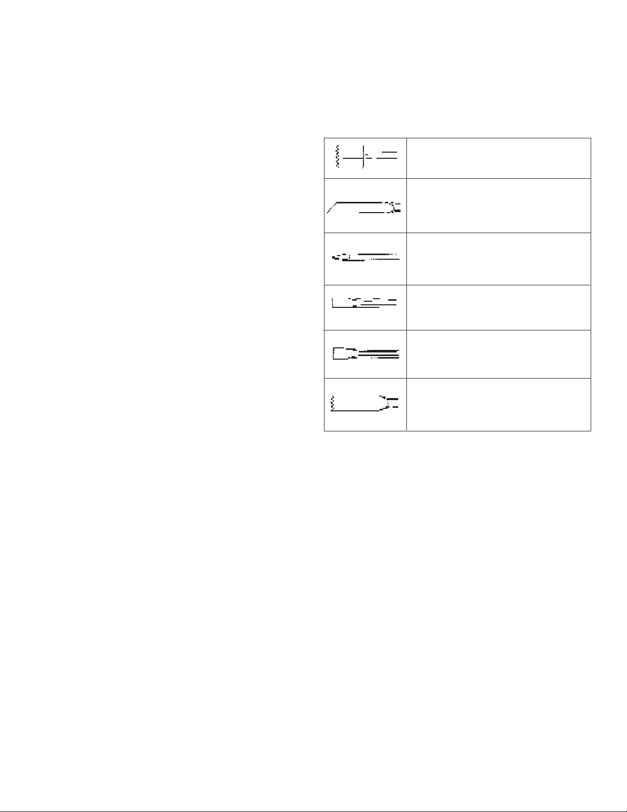
1. Coloque el portaherramientas para anclajes de tamaño adecuado en
el adaptador cónico tipo “B”. Luego coloque el adaptador “B” dentro
de la herramienta y asegúrelo tal y como se describe en “Colocación
de brocas y cinceles”.
2. Inserte el anclaje en el portaherramientas para anclaje. Coloque la
perilla de detención de la rotación en la posición de martilleo
solamente. Luego coloque el anclaje en el lugar indicado y martillee
hasta que los dientes hayan penetrado en el concreto (Fig. 11).
3. Cambie la perilla de detención de la rotación a la posición de martilleo
con rotación y perfore hasta que el portaherramientas este a unos
3mm por encima del concreto (Fig. 12).
NOTA: puede ser necesario limpiar varias veces el polvo y residuos
del anclaje durante la operación.
4. Retire el anclaje de la perforación, con la unidad encendida. Limpie
el polvo y residuos del anclaje apuntando el martillo hacia abajo, y
encendiéndolo y apagándolo varias veces. Limpie el polvo de dentro
de la perforación usando una aspiradora o una boca de soplado
(Fig. 13).
5. Coloque el taco expandible en el interior del anclaje e inserte éste en
la perforación. Cambie nuevamente la posición de la perilla de
detención de rotación a martilleo solamente, y martillee firmemente el
anclaje en la perforación (Fig. 14).
6. Desprenda la cabeza del anclaje. Para retirar la cabeza de anclajes
de hasta 16mm, agarre las empuñaduras firmemente y tire de la
herramienta hacia usted con un esfuerzo en seco (Fig. 15) o
desprenda la cabeza del anclaje con un martillo de mano, tal y como
se muestra (Fig. 16). El anclaje ya está listo para recibir un perno.
7. Para retirar la cabeza del anclaje incrustada en el portaherramientas
de anclaje utilice el eyector 9170 0888 40.
8. Para retirar el portaherramientas del anclaje, retire el adaptador “B”
de la nariz de la herramienta. Inserte el perno extractor, que viene
con el adaptador, en la perforación lateral que tiene el adaptador
“B”, y golpee firmemente hasta que se desprenda el porta
herramientas.
Cincelado y corte
Estos rotatorios pueden utilizarse para trabajos livianos de corte y
cincelado.
Cuando cincele, mantenga la herramienta a un ángulo con la pieza de
trabajo. Trabaje desde una esquina o cerca del borde del área de trabajo,
rompiendo poco a poco, más que intentando romper un área demasiado
grande.
Hay una variedad de accesorios disponibles:
Martelinas
Para superficies de concreto
Cinceles para cortar mortero
Para la remoción de mortero viejo o retoques
Cinceles con punta
Para trabajos de demolición e inicio de
perforación en losas de concreto
Cinceles en plano
Para orillar, eliminar rebabas o para acanalar.
Cinceles desincrustadores
Para la remoción de salpicaduras de soldadura
o corte de líneas rectas
Cinceles de ranurado
Para acanalar o cortar entre agujeros
perforados en concreto y mampostería.
page 26

MANTENIMIENTO
¡ADVERTENCIA!
Para reducir el riesgo de lesiones, desconecte
siempre la herramienta antes de darle cualquier
mantenimiento. Nunca desarme la herramienta ni trate
de hacer modificaciones en el sistema eléctrico de
la misma. Comuníquese con un representante de
servicio autorizado en relación con TODOS los trabajos
de reparación.
Mantenimiento de las herramientas
Adopte un programa regular de mantenimiento y mantenga su herramienta
en buenas condiciones. Antes de usarla, examine las condiciones generales de la misma. Inspeccione guardas, interruptores, el cable de la
herramienta y el cable de extensión. Busque tornillos sueltos o flojos,
defectos de alineación y dobleces en partes móviles, así como montajes
inadecuados, partes rotas y cualquier otra condición que pueda afectar
una operación segura. Si detecta ruidos o vibraciones anormales, apague
la herramienta de inmediato y corrija el problema antes de volver a usarla.
No utilice una herramienta dañada. Colóquele una etiqueta que diga “NO
DEBE USARSE” hasta que sea reparada (vea “Reparaciones”).
Bajo condiciones normales, no se requiere lubricación hasta que haya
que cambiar los carbones. Después de un intervalo de seis a doce
meses, según el uso de la herramienta, llévela a su representante de
servicio autorizado más cercano para que realice los siguientes trabajos
de mantenimiento:
• Lubricación
• Inspección y cambio de carbones
• Inspección mecánica y limpieza (engranes, flechas, baleros,
carcarza, etc.)
• Inspección eléctrica (interruptor, cable, armadura, etc.)
• Probarla para asegurar una operación mecánica y eléctrica
adecuada.
¡ADVERTENCIA!
Para reducir el riesgo de lesiones, descarga eléctrica o
daño a la herramienta, nunca la sumerja en líquidos ni
permita que estos fluyan dentro de la misma.
Limpieza
Limpie el polvo y suciedad de las ventilas. Mantenga las empuñaduras
de la herramienta limpias, secas y libres de aceite y grasa. Use sólo
jabón neutro y un trapo húmedo para limpiar su herramienta ya que
algunas substancias y disolventes limpiadores pueden ocasionar daños
a materiales plásticos y partes aislantes. Algunos de estos incluyen:
gasolina, trementina, diluyente para barniz, diluyente para pintura,
disolventes limpiadores clorados, amoníaco, y detergentes caseros que
contengan amoníaco.
Reparaciones
Si se daña o descompone, envíe la herramienta y todos sus accesorios
al centro de servicio más cercano de los listados en la cubierta posterior
de este manual del operario.
ACCESORIOS
Remítase al catálogo de accesorios para obtener una lista completa. Si
desea obtener un catálogo, consulte la lista de representantes de servicio
autorizados para conocer cuál es el más cercano a usted.
page 27

Atlas Copco Berema AB, Sickla Industriväg 1A, S-105 23
Nacka Stockholm
Telephone: +46 (0) 8 743 9600 Fax: +44 (0) 8 743 9650
58-14-0800d2 No. 9800 7126 93 10/00 Printed in U.S.A.
page 28
 Loading...