

Page 1
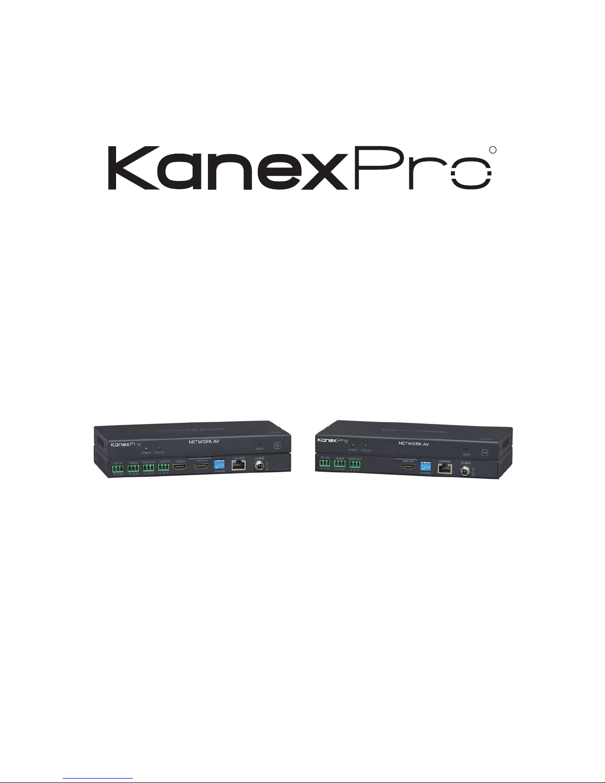
NetworkAV™ over IP Sender &
Receiver w / Central Control &
PoE
EXT-NETAVTX
EXT-NETAVRX
All Rights Reserved
EXT-NETAVRX_V1.0
RR
Page 2

Statement
Read this user manual carefully before using the product. Pictures shown
in this manual is for reference only. Different models and specifications
are subject to real product. This manual is only for operation instruction only.
The functions described in this version are updated as of May 31st, 2018.
In the constant effort to improve our product, we reserve the right to make
functions or parameters changes without notice or obligation. Please refer to
the dealers for the latest details.
Safety Precaution
To insure the best from the product, please read all instructions carefully before
using the device. Save this manual for further reference.
Follow basic safety precautions to reduce the risk of fire, electrical shock and
injury to persons.
● Do not dismantle the housing or modify the module to avoid electrical
shock or burn.
● Using supplies or parts not meeting the products’ specifications may
cause damage, deterioration or malfunction.
● Do not expose the unit to rain, moisture or install this product near water.
● Install the device in a place with fine ventilation.
● Do not twist or pull by force ends of the CAT5e/CAT6a cable. It can
cause malfunction.
● Do not use liquid or aerosol cleaners to clean this unit. Always unplug
the power to the device before cleaning.
● Unplug the power cord when left unused for a long period of time.
● Refer all servicing to qualified service personnel.
Customer Service
We provide limited warranty for the product within three years. Contact us at
(888)-975-1368 For more details, please contact your distributor or dealer.
Or email us directly to [email protected]
R
EXT-NETAVRX_V1.0
1
Page 3
Surge protection device recommended
This product contains sensitive electrical components that may be damaged
by electrical spikes, surges, electric shock, lightning strikes, etc. Use of surge
protection systems is highly recommended in order to protect and extend
the life of your equipment.
Revision History
Version No. Date Changes
V1.0
R
2
EXT-NETAVRX_V1.0
Page 4

Table of Contents
R
3
1. Introduction.................................................................................
2. Features.......................................................................................
3. Package Contents.......................................................................
4. Specifications..............................................................................
5. Operation Controls and Functions............................................
6. Connection Diagram...................................................................
7. Installation & Setup.....................................................................
4
4
4
5
6-8
9
10-22
EXT-NETAVRX_V1.0
Page 5

1. Introduction
The KanexPro EXT-NETAV is a total solution package for those looking to
distribute multiple HD content to multiple HD displays over IP with an easy
to use built-in controller over a standard 1G network switch.
Compliant with HDCP, this set of Sender and Receiver offers configurable
high quality, low-bandwidth H.264 compression video supporting resolutions
up to 1920x1080@60fps. It’s a great solution for those looking to upgrade
the traditional DVI/HDMI matrix switchers.
2. Features
● Encode & Decode AV over IP up to 495ft. (120m)
● Create a Video Wall or a Multiview experience with 100's of screens
● Unicast, Multicast, Matrix, Video Wall and Multi-viewer (up to 5 windows)
● Unlimited scalability (based on network topology)
● Low 1.5 frames per second latency
● Video resolution up to 1080p/60Hz (4:4:4)
● Supports Audio Embedding on the Sender
● Supports Audio De-embedding on the Receiver
● Works with 1G standard managed network switch
● Works with IP Camera
● H.264 Encoding/Decoding compression
● Local HDMI output on sender
● Control via RS-232 & Web-based GUI controller built-into the Sender
● POE - No power supply needed if using POE managed network switch
● Compact design for an easy and flexible installation to rack
● Backed by KanexPro 3-year parts and labor warranty
R
4
3. Package Contents
1 x NetworkAV™ Decoder
1 x DC 12V Power Adaptor
1 x User Manual
EXT-NETAVRX_V1.0
Page 6
4. Specifications
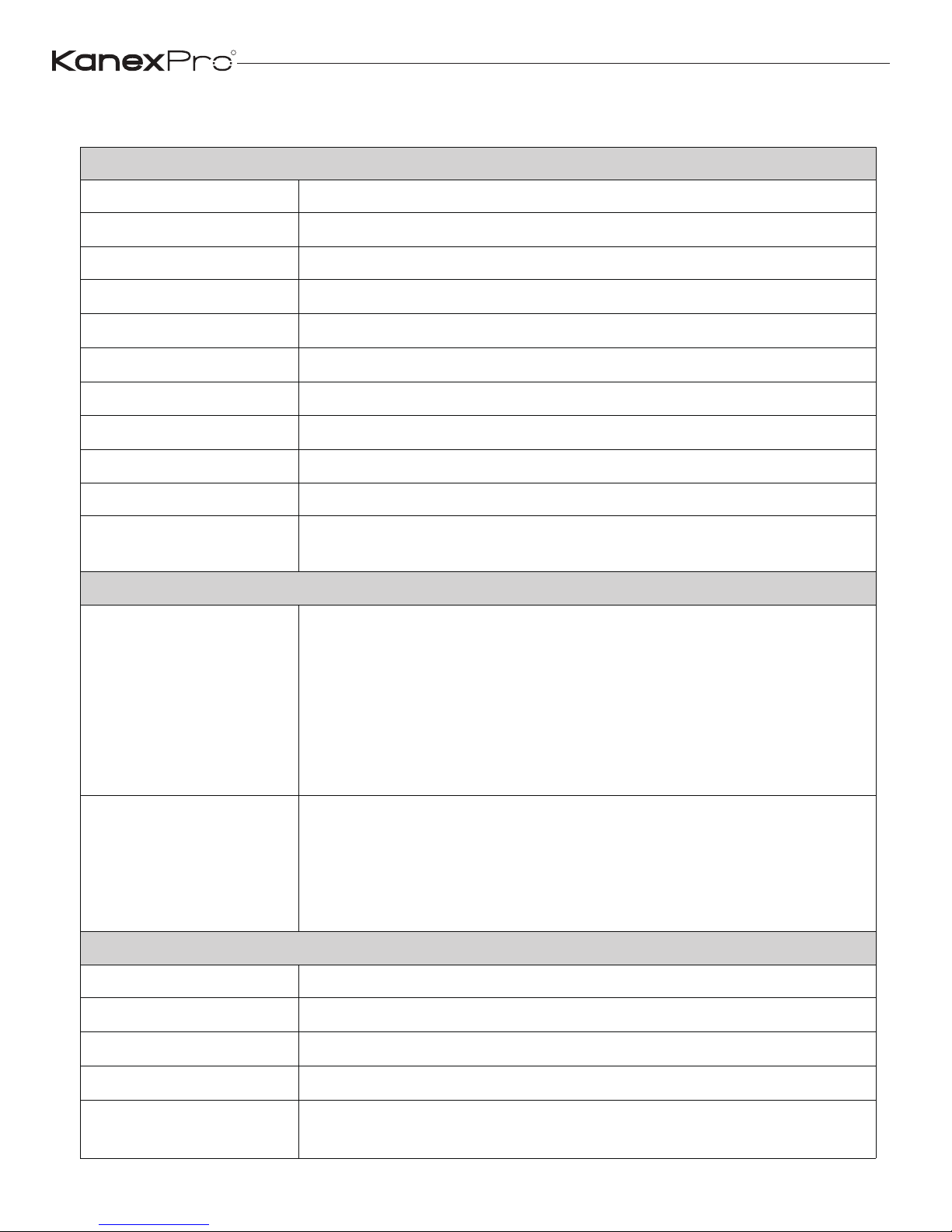
Technical
HDMI Compliance HDMI 1.4b
HDCP Compliance HDCP 1.4
Video Bandwidth 4.95Gbps
Video Resolutions 640x480p@60Hz ~ 1920x1080p@60Hz
Output Video Type H.264/MPEG-4 AVC
Encoding Data Rate Up to 30Mbps, configurable
Color Space RGB, YCbCr 4:4:4, YCbCr 4:2:2
Color Depth 8-bit
HDMI Audio Formats LPCM 2CH, 48KHz
L/R Audio Formats Analog Stereo 2CH
ESD Protection
Human body model — ±8kV (air-gap discharge) &
±4kV (contact discharge)
Connections
Sender
Inputs: 1x HDMI Type A [19-pin female]
1x L/R Audio In [3.81mm Phoenix connector]
1x RS-232 [3.81mm Phoenix connector]
Outputs: 1x LAN [RJ45 connector]
1x HDMI Type A [19-pin female]
1x L/R Audio Out [3.81mm Phoenix connector]
1x Debug [3.81mm Phoenix connector]
Receiver
Inputs: 1x LAN [RJ45 connector]
Outputs: 1x HDMI Type A [19-pin female]
1x L/R Audio Out [3.81mm Phoenix connector]
1x RS-232 [3.81mm Phoenix connector]
1x Debug [3.81mm Phoenix connector]
Mechanical
Housing Metal Enclosure
Color Black
Dimensions 200mm [W] x 103mm [D] x 20mm [H]
Weight Sender: 530g, Receiver: 526g
Power Supply
Input: AC100 - 240V 50/60Hz
Output: DC 12V/1A (US/EU standards, CE/FCC/UL certified)
R
5
EXT-NETAVRX_V1.0
Page 7
Power Consumption Sender: 5.7W (Max), Receiver: 5.6W (Max)
Operation Temperature 32 - 104°F / 0 - 40°C
Storage temperature -4 - 140°F / -20 - 60°C
Relative Humidity 20 - 90% RH (no condensation)
5. Operation Controls and Functions
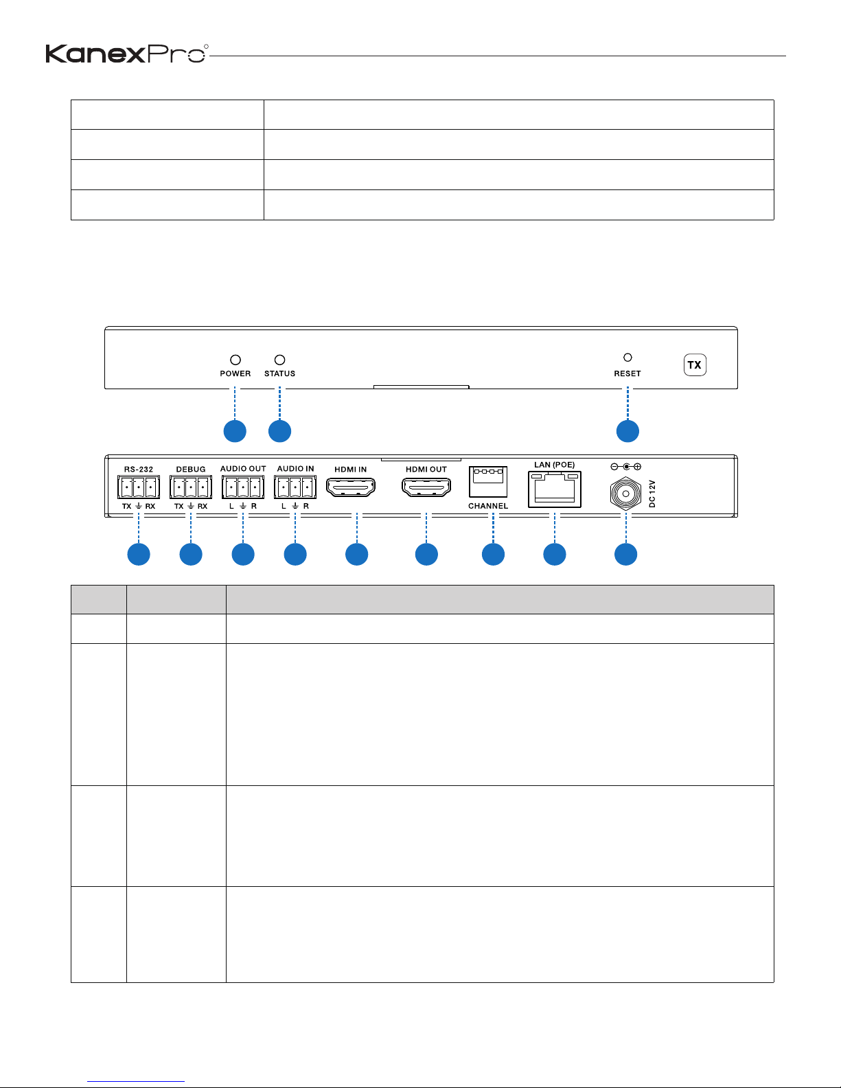
5.1 Sender
1
2
3
4 5 86 7 9 10 11 12
Items Name
1 POWER System power status LED
Description
2 STATUS
System working status LED
One second period flickering means product working normally.
Always on means system worked abnormally, this time you need
to reset product by pressing reset button on the front panel or
plugging power supply on the rear panel (you need plug CAT
cable if product is using POE for power supply).
3 RESET
System reset button.
Short pressing (<5 seconds) will reset product.
Long pressing (over 5 seconds) will let product enter firmware
upgrade mode.
4 RS-232
Connect third-party control system to control this product utilizing
our API commands or control other devices be connected to our
products (including Senders and Receivers) via RS-232 port
(this is called RS-232 pass-through).
R
6
EXT-NETAVRX_V1.0
Page 8
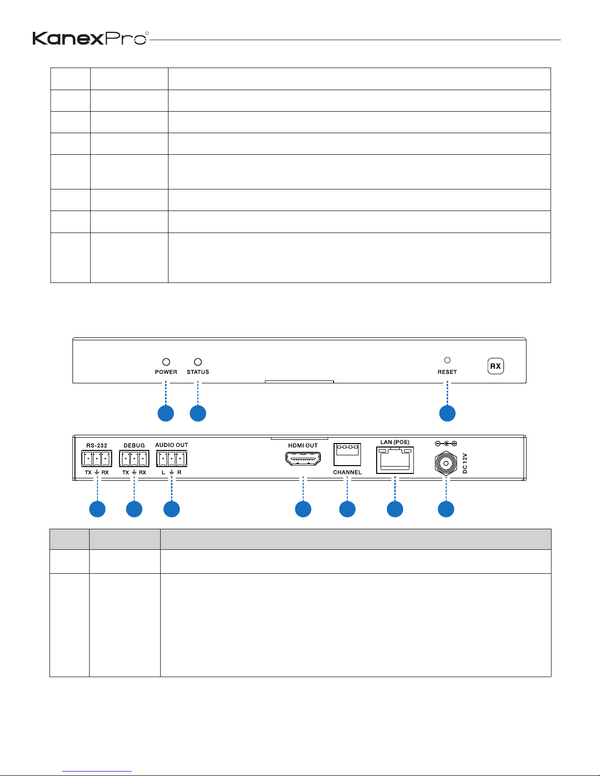
5 DEBUG System debug port
6 AUDIO OUT Analog stereo audio output
7 AUDIO IN Analog stereo audio input
8 HDMI IN HDMI input port, connect to HDMI source device
9 HDMI OUT
HDMI loop out (default video only no audio, you can enable
audio from Web GUI or API)
10 CHANNEL Reserved use
11 LAN(POE) Connects with Hub or router for sending data to Receiver.
12 DC 12V
Connects with 12V/1A power adapter supplied in the package
or doesn’t need this if an IP switcher/router/hub with POE feature
be connected.
5.2 Receiver
1
2 3
4 5 6 7 8 9
10
Items Name Description
1 POWER System power status LED
2 STATUS
System working status LED
One second period flickering means product working normally.
Always on means system worked abnormally, this time you need
to reset product by pressing reset button on the front panel or
plugging power supply on the rear panel (you need plug CAT
cable if product is using POE for power supply).
R
7
EXT-NETAVRX_V1.0
Page 9
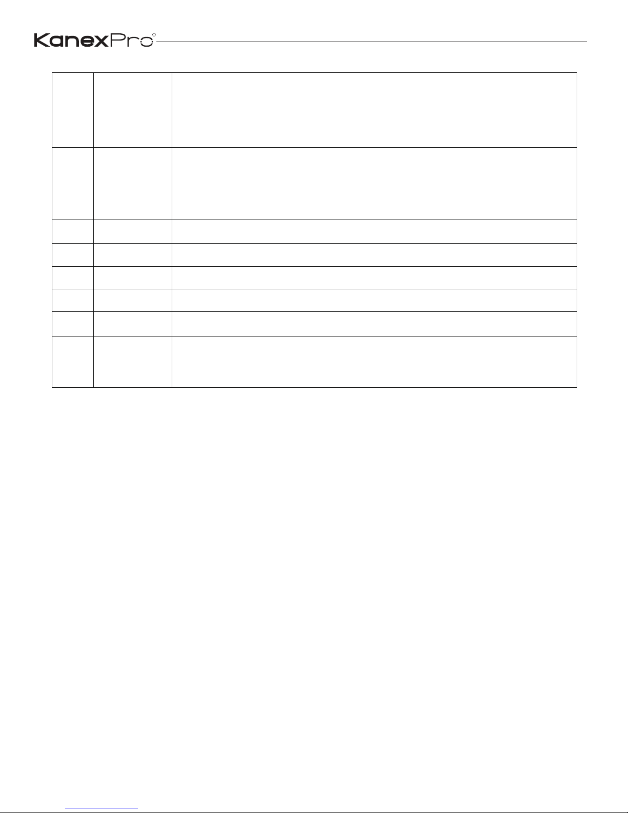
3 RESET
System reset button.
Short pressing (<5 seconds) will reset product.
Long pressing (over 5 seconds) will let product enter firmware
upgrade mode.
4 RS-232
Connect third-party control system to control this product utilizing
our API commands or control other devices be connected to our
products (including Senders and Receivers) via RS-232 port (this
is called RS-232 pass-through).
5 DEBUG System debug port
6 AUDIO OUT Analog stereo audio output
HDMI OUT7 HDMI output port, connect to HDMI display device
CHANNEL8 Reserved use
9 LAN(POE) Connects with Hub or router for receiving data to Sender.
10 DC 12V
Connects with 12V/1A power adapter supplied in the package
or doesn’t need this if an IP switcher/router/hub with POE feature
be connected.
R
8
EXT-NETAVRX_V1.0
Page 10
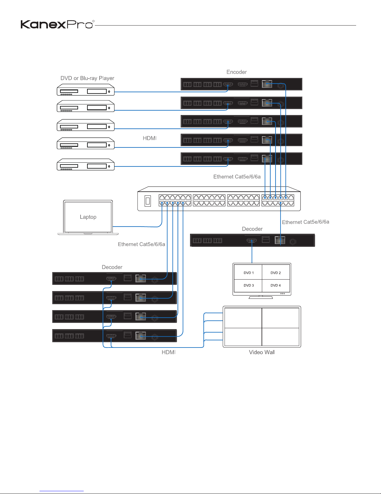
6. Connection Diagram
R
9
EXT-NETAVRX_V1.0
Page 11
7. Installation & Setup
7.1 Basic Instructions
1. The set of sender and receiver can form a complex AV over IP system
that supports Web-based GUI controlling and management.
2. Any Sender can be turn into master controller just by selecting the master
controller option from the web-based GUI management system.
3. Once the master controller role is assigned to sender, then the same
sender can be used to configure all the sender and receiver connected
in the network.
4. Master controller can be accessed using the default login credentials.
A step by step configuration for first time installation
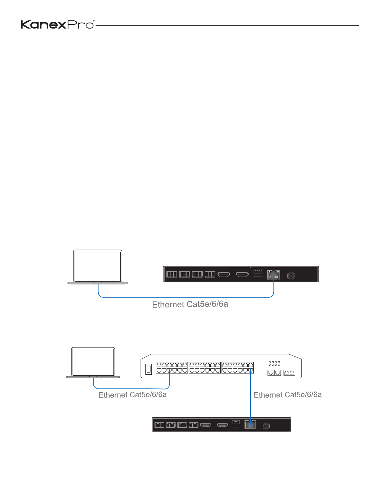
(1) Choose a Sender box as “Master Controller”, you can connect sender
to your laptop through CAT5e/6 cable directly or through a managed network
switch as shown below:
Encoder
Laptop
Figure 1: Laptop connects to Controller directly
Laptop
Encoder
Figure 2: Laptop and Controller both connect to switcher
R
10
EXT-NETAVRX_V1.0
Page 12
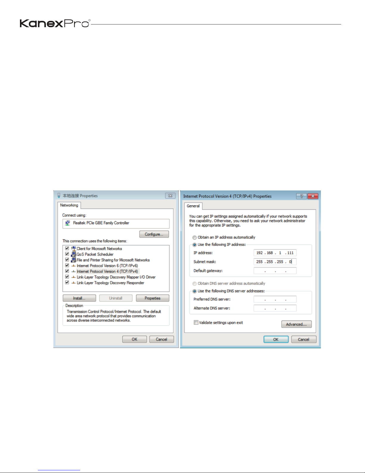
Note: If you have configured the connection as described above then please
have only one Sender (Master controller) connected to the switch.
All Senders have the same default IP address: 192.168.1.28.
All Receivers have the same default IP address: 192.168.1.38.
Kindly update the IP address of sender which you have decided to make
the master controller. Once the IP address of the Master controller is changed
then you can configure all the senders and receivers connected in the network.
(2) Set your laptop IP setting to the same domain with Controller so that
you can login Controller’s Web page, for instance set laptop IP address to
192.168.1.111
(3) Login Master Controller Web page by typing in your default IP address
(192.168.1.28) in your internet browser.
Username: admin
Default don’t need password to login.
R
11
EXT-NETAVRX_V1.0
Page 13
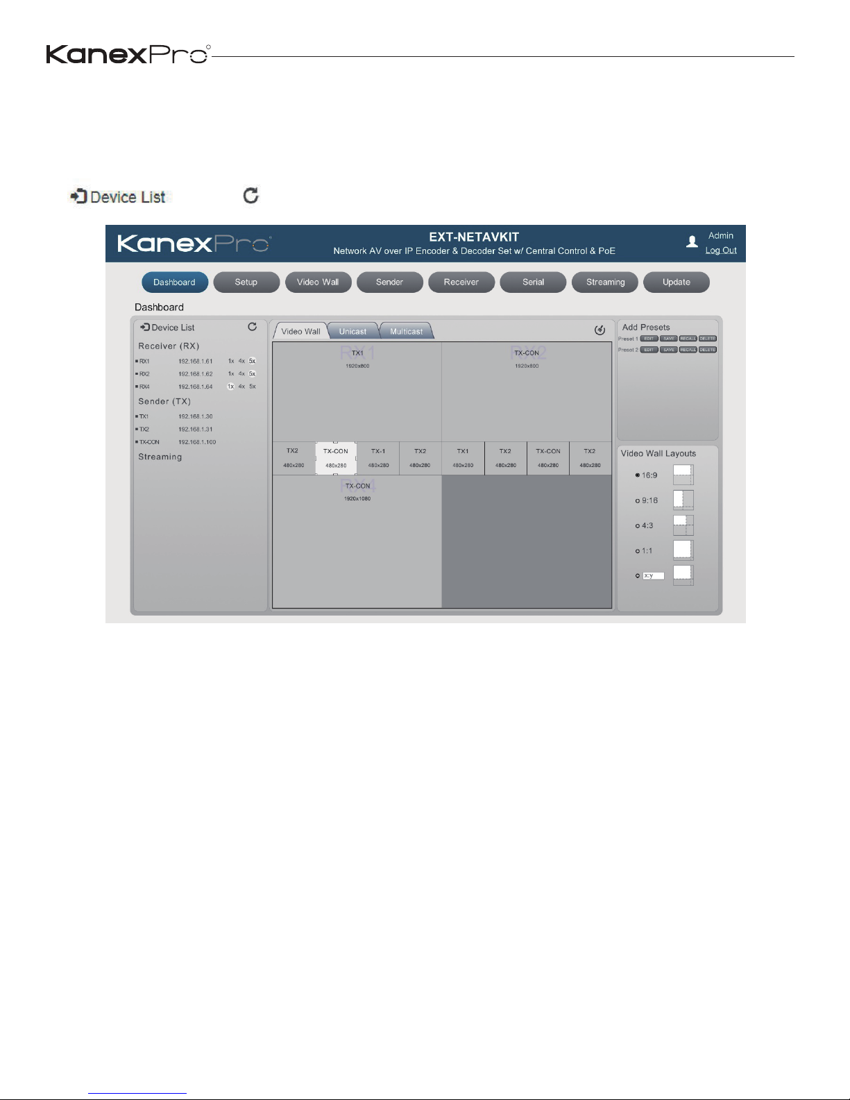
As per the screen shot of the Dashboard below, please click searching
devices icon (Right to the Device List) to search all Senders and Receivers
in the network.
R
12
EXT-NETAVRX_V1.0
Page 14
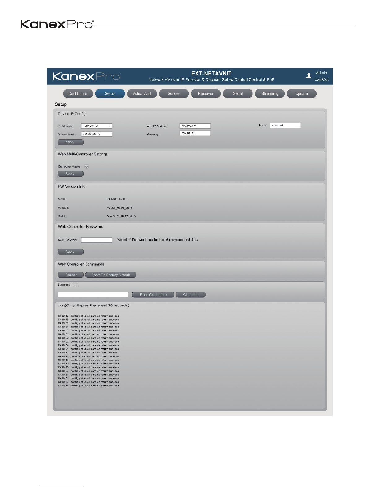
Please go to Setup page and change the default sender IP address to any
other IP Address. For instance, 192.168.1.61 as shown in the image below.
R
13
EXT-NETAVRX_V1.0
Page 15
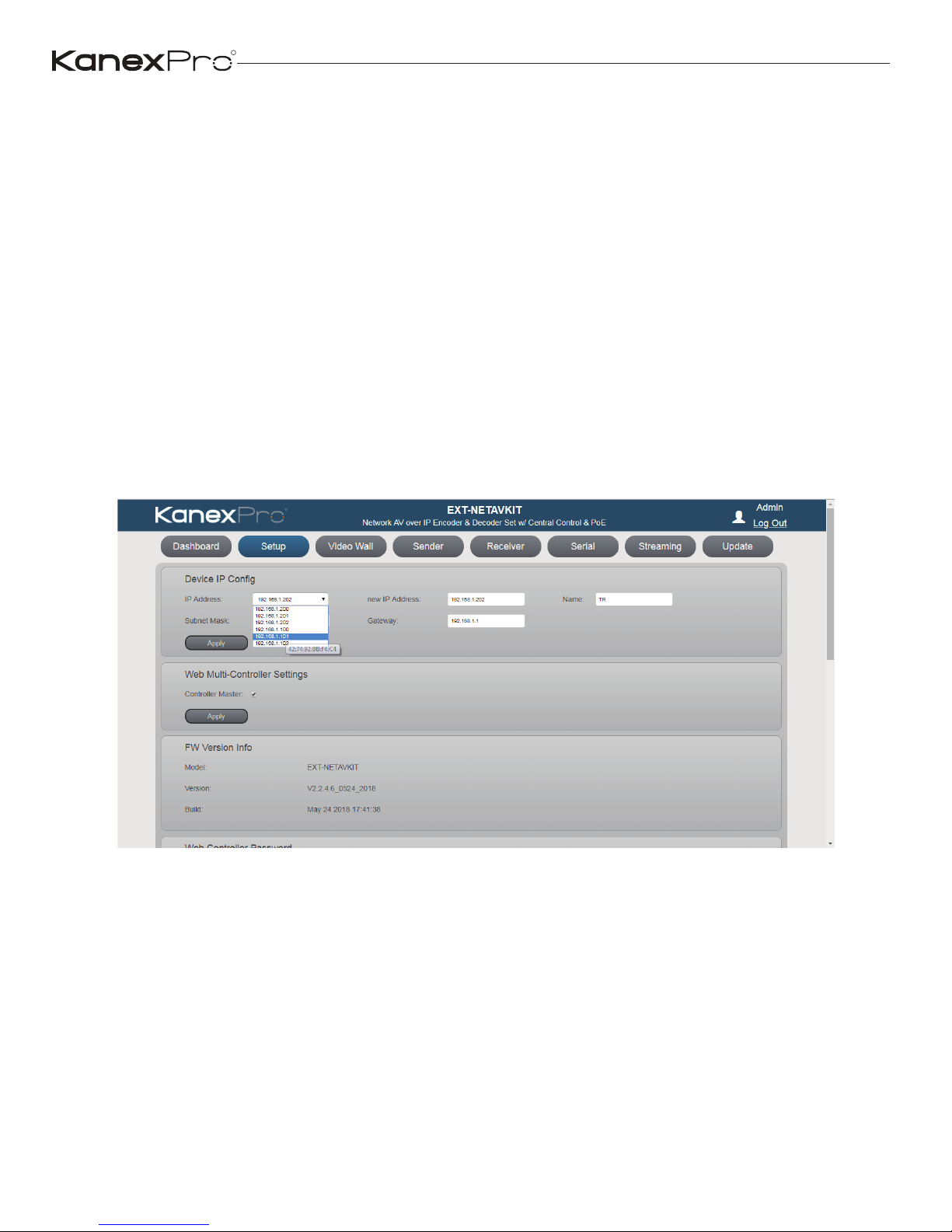
Once the Main controller (Sender) IP address is changed then you can
change the other sender and receiver IP address.
Note: During changing Senders and Receivers IP address, you can see
their MAC address on the Web page (as below picture). Receiver will display
its own IP address and firmware version information on the corresponding
display. So, you would easily identify which Receiver you’re changing.
If all the sender’s are connected at the same time, each sender’s ip address
need to change as per the Mac address labeled at the bottom of the housing.
Otherwise, connect each sender at a time and change the IP address accordingly.
SETUP
R
14
EXT-NETAVRX_V1.0
Page 16
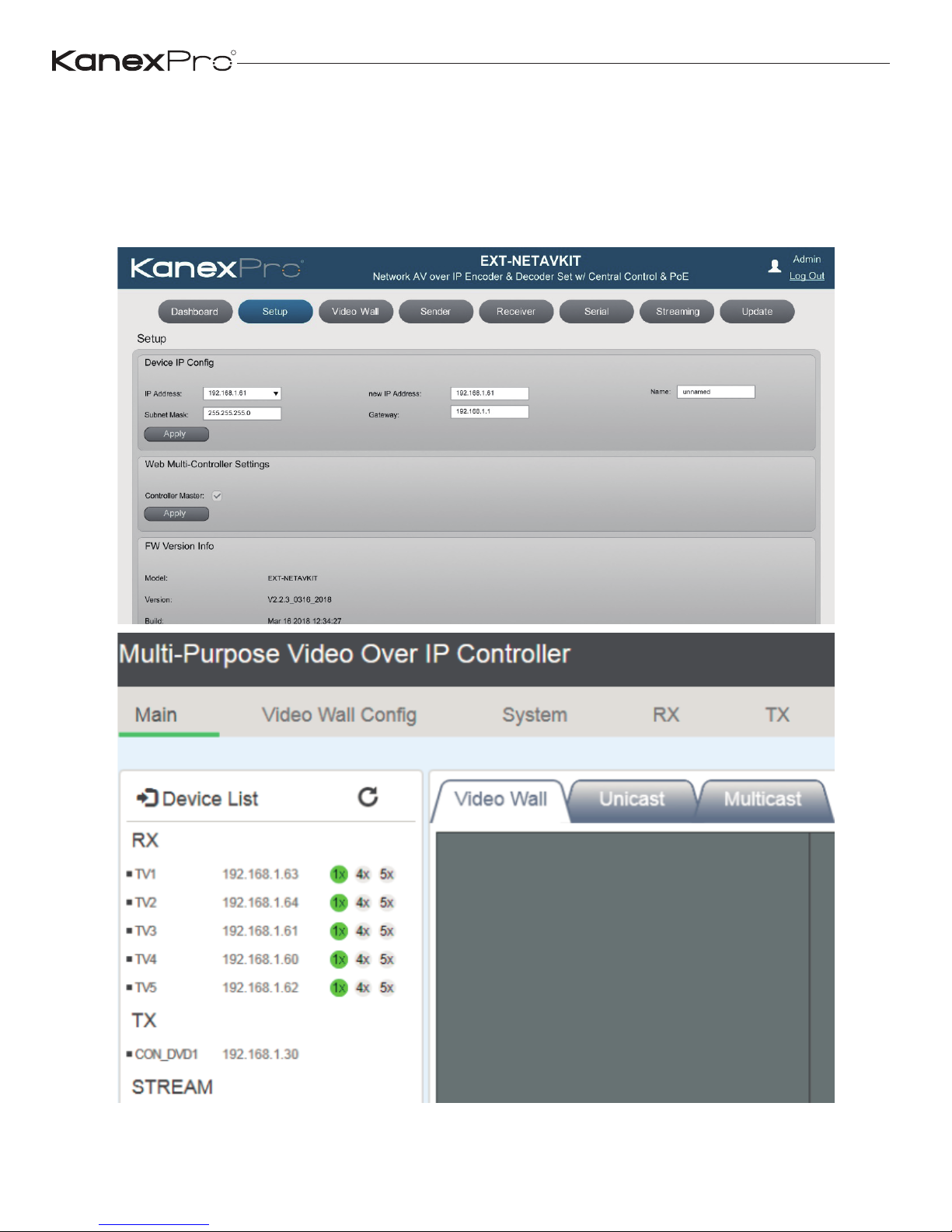
Rename Sender/ Receiver
You can also label the sender and receiver IP address for as per your sources
and display connected. Please use the Field NAME on the right of New IP
address.
R
15
EXT-NETAVRX_V1.0
Page 17
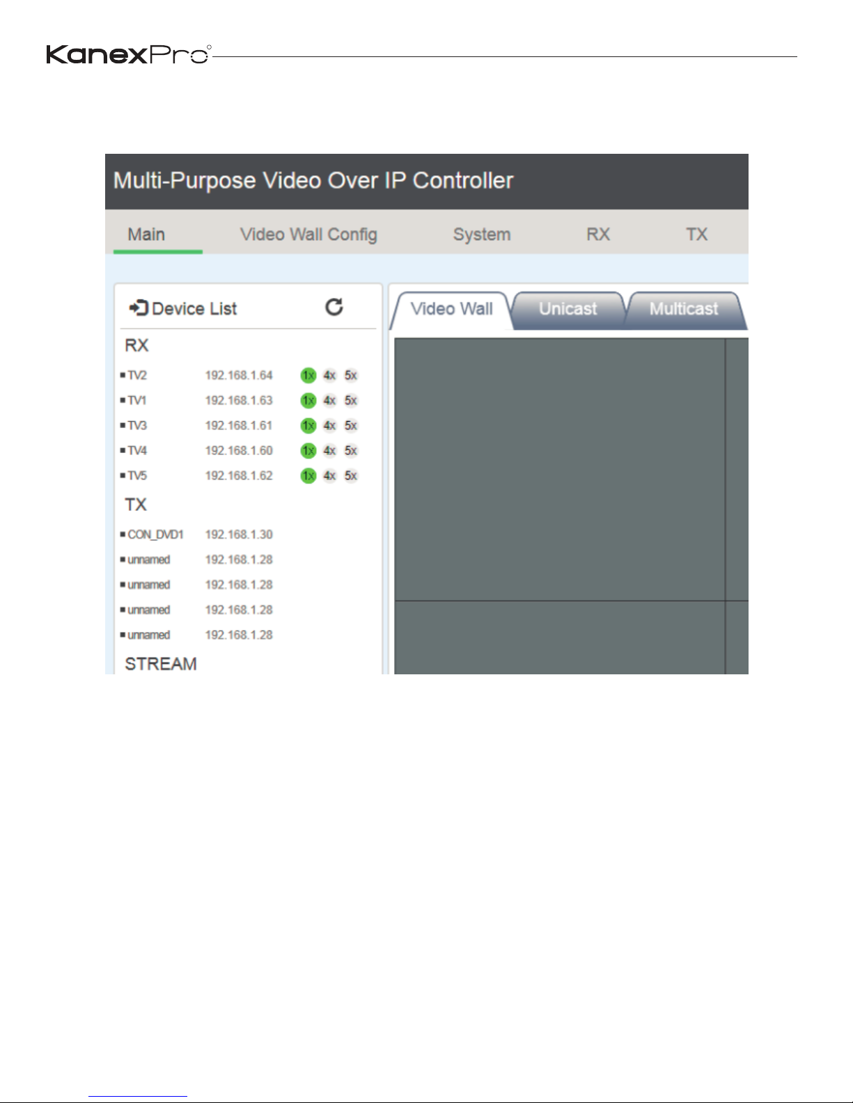
(4) Now you can put other Senders into system, and click “searching
devices” icon:
R
16
EXT-NETAVRX_V1.0
Page 18
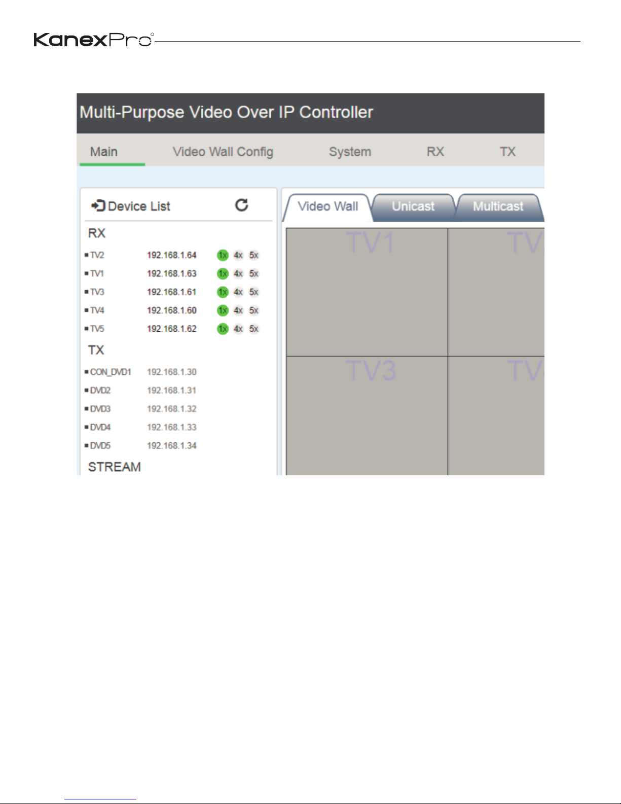
Please change every one’s IP address and name like above steps:
R
17
EXT-NETAVRX_V1.0
Page 19
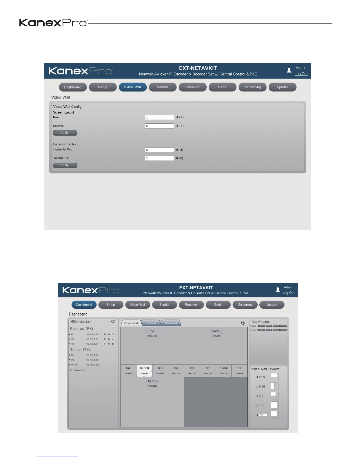
(5) Please set video wall parameters according to your system setup. For
instance set to 2x2.
Go to Main page, you can see below 3x3 video wall layout, and you should
drag each Receiver (put your cursor on the RX’s IP address position) to
each window position firstly. Then you also can drag each Sender to the
RX window you want.
R
18
EXT-NETAVRX_V1.0
Page 20
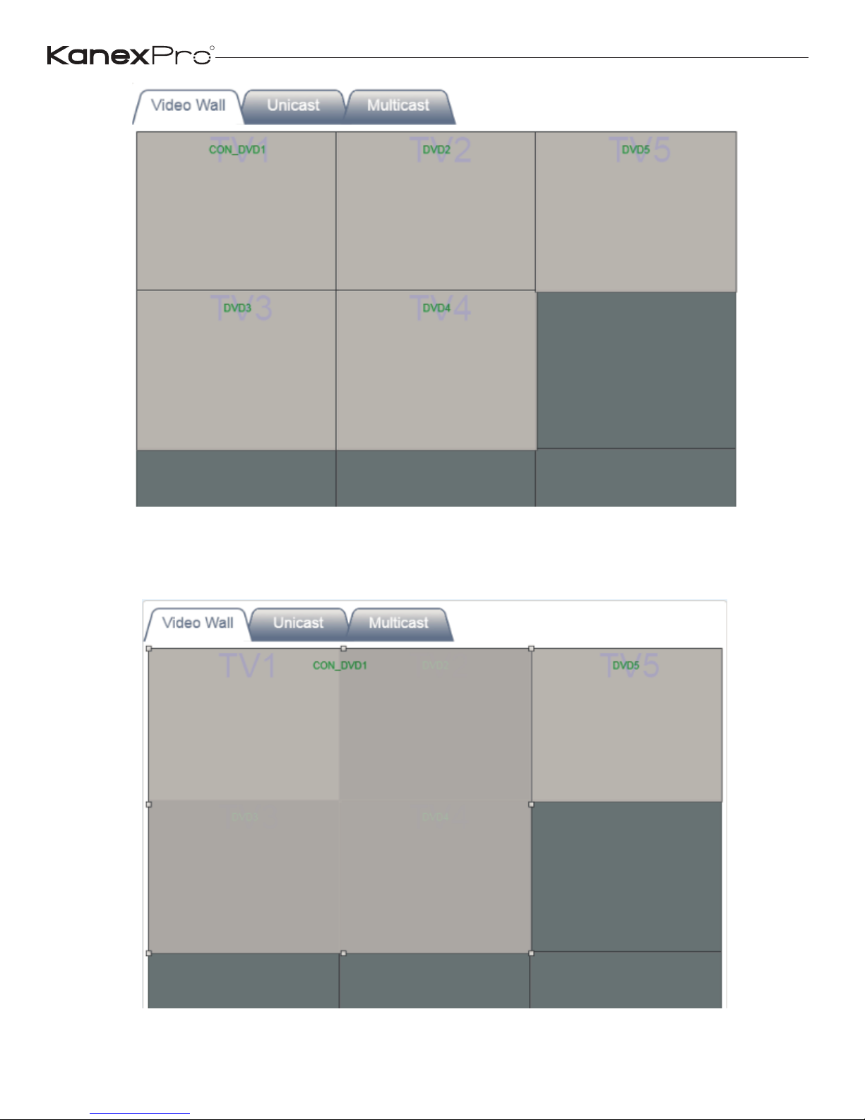
You can drag one video source cross to 4 RX windows (max up to 4x4 16
RX windows) to create a video wall like below.
R
19
EXT-NETAVRX_V1.0
Page 21
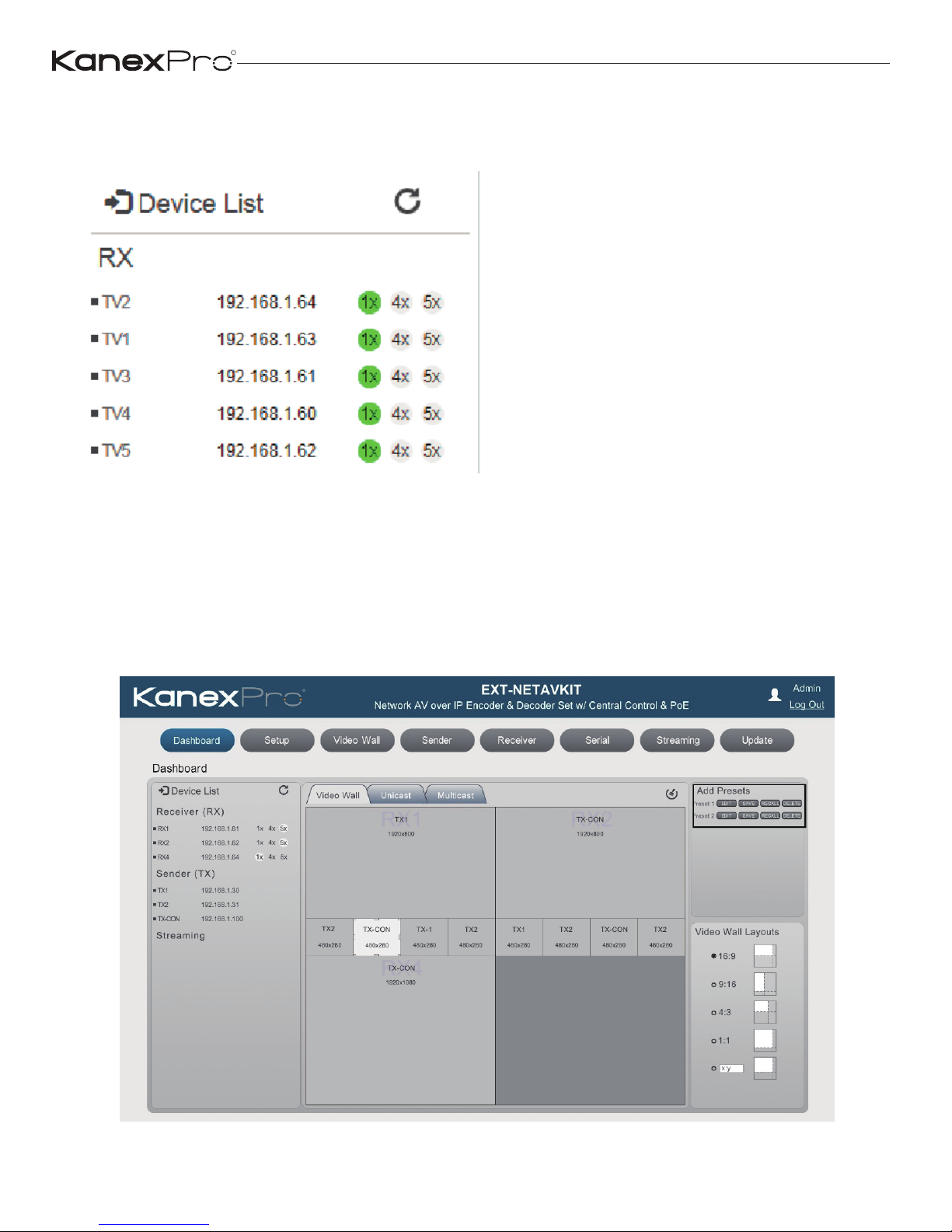
You also can set multi-view mode by clicking 4x or 5x icon for each Receiver
box:
(6) After you complete all system configurations, current settings would be
saved into current Controller box, it will be run automatically at next system
power up. Of course, you can also save current configurations to a scene
and take a name you want by clicking “Add Scene” icon. You can recall
different scenes to reload different system configurations according to your
applications.
R
20
EXT-NETAVRX_V1.0
Page 22
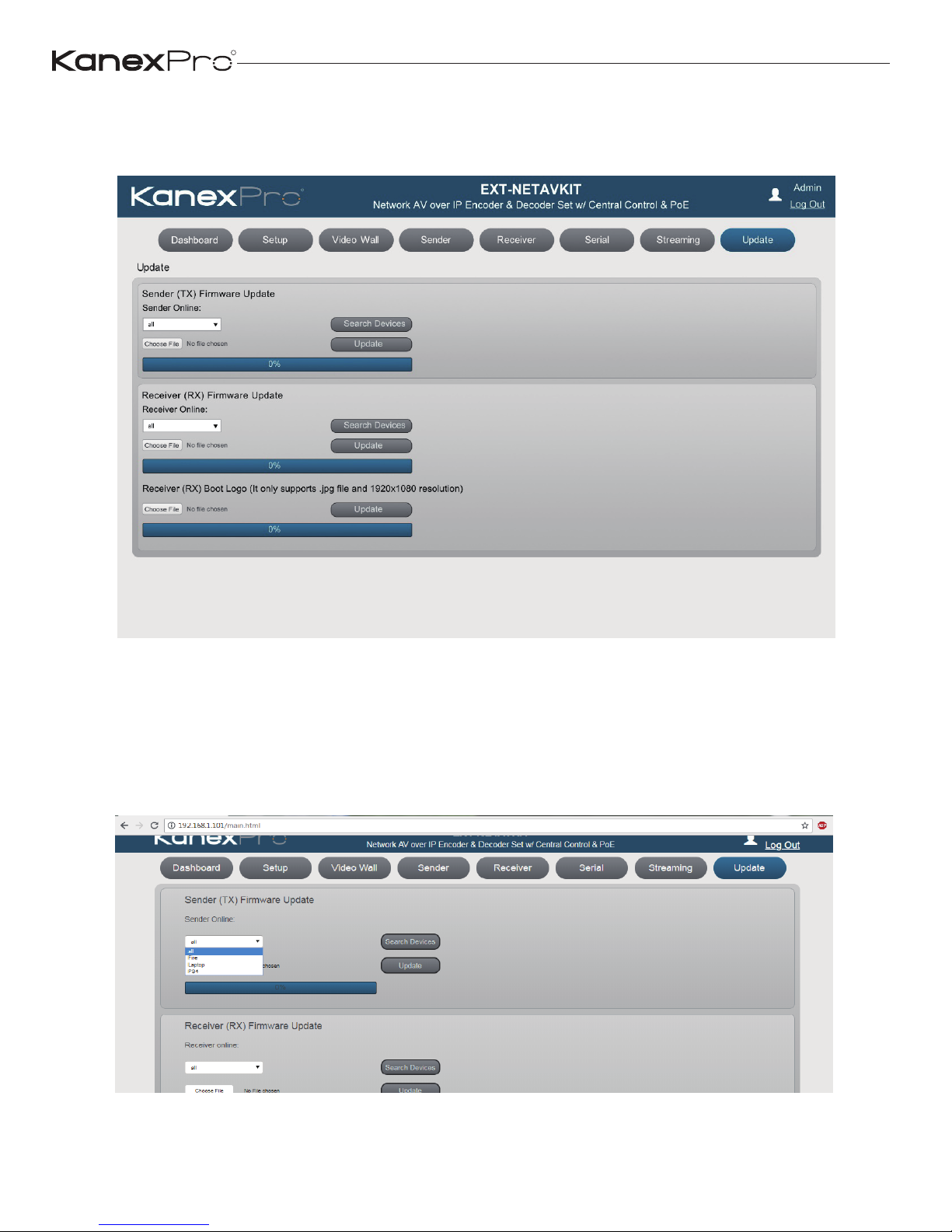
7.2 Firmware Update
Open the Update tab to update the firmware of sender and receiver.
Firmware update can be done for all the sender and receiver by selecting
option ALL.
Firmware update can also be performed as per each sender or receiver.
R
21
EXT-NETAVRX_V1.0
Page 23

7.3 Control Using Third-party controller
Please contact supplier for the API commands documents.
Customer Services
The return of a product to our Customer Service implies the full agreement
of the terms and conditions hereinafter. There terms and conditions may be
changed without prior notice.
① Warranty
The limited warranty period of the product is fixed 3 (three) years.
② Scope
These terms and conditions of Customer Service apply to the customer
service provided for the products or any other items sold by authorized
distributor only.
③ Warranty Exclusions:
Warranty expiration.
Factory applied serial number has been altered or removed from the product.
Damage, deterioration or malfunction caused by:
√ Normal wear and tear.
√ Use of supplies or parts not meeting our specifications.
√ No certificate or invoice as the proof of warranty.
√ The product model showed on the warranty card does not match with
the model of the product for repairing or had been altered.
√ Damage caused by force majeure.
√ Servicing not authorized by distributor.
√ Any other causes which does not relate to a product defect.
R
22
EXT-NETAVRX_V1.0
Page 24

Shipping fees, installation or labor charges for installation or setup of the
product.
④ Documentation:
Customer Service will accept defective product(s) in the scope of warranty
coverage at the sole condition that the defeat has been clearly defined, and
upon reception of the documents or copy of invoice, indicating the date of
purchase, the type of product, the serial number, and the name of distributor.
Remarks: For further assistance or solutions, please contact your local
distributor or email directly to us at [email protected]
R
Brea, California
www.kanexpro.com
R
23
EXT-NETAVRX_V1.0
 Loading...