

Kanardia Daqu Installation Manual
Daqu EMS Box
Installation Manual
Kanardia d.o.o.
January 2019
©
Kanardia d.o.o.


Daqu — Manual
Contact Information
Publisher and producer:
Kanardia d.o.o.
Lopata 24a
SI-3000
Slovenia
Tel: +386 40 190 951
Email: info@kanardia.eu
A lot of useful and recent information can be also found on the Internet. See
http://www.kanardia.eu for more details.
Copyright
This document is published under the Creative Commons, Attribution-ShareAlike 3.0 Unported licence. Full license is available on http://creativecommons.
org/licenses/by-sa/3.0/legalcode web page and a bit more human readable summary is given on
http://creativecommons.org/licenses/by-sa/3.0/. In short, the license
gives you right to copy, reproduce and modify this document if:
you cite Kanardia d.o.o. as the author of the original work,
you distribute the resulting work only under the same or similar license
to this one.
Credits
This document was written using TeX Live (LATEX) based document creation
system using Kile running on Linux operating system. Most of the figures were
drawn using Open Office Draw, Inkscape and QCad applications. Photos and
scanned material was processed using Gimp. All document sources are freely
available on request under the licence mentioned above and can be obtained
by email. Please send requests to info@kanardia.eu.
1
©
Kanardia 2019

Daqu — Manual
Revision History
The following table shows the revision history of this document.
Rev. Date Description
1.0 January 2019 Release
©
Kanardia 2019 2

Daqu — Manual CONTENTS
Contents
1 Introduction 6
1.1 General Description . . . . . . . . . . . . . . . . . . . . . . . . 6
1.2 Channels . . . . . . . . . . . . . . . . . . . . . . . . . . . . . . 7
1.2.1 Analog Channels . . . . . . . . . . . . . . . . . . . . . . 7
1.2.2 Digital Channels . . . . . . . . . . . . . . . . . . . . . . 8
1.3 Technical Specifications . . . . . . . . . . . . . . . . . . . . . . 8
2 Installation 10
2.1 General Rules . . . . . . . . . . . . . . . . . . . . . . . . . . . . 10
2.2 Intake Manifold Pressure . . . . . . . . . . . . . . . . . . . . . . 11
2.3 Connectors and Cables . . . . . . . . . . . . . . . . . . . . . . . 12
2.3.1 CAN Bus Cable . . . . . . . . . . . . . . . . . . . . . . 12
3 Wiring in General 13
3.1 Connection Wires . . . . . . . . . . . . . . . . . . . . . . . . . . 13
3.2 Daqu Ground Pin (GND) . . . . . . . . . . . . . . . . . . . . . 13
3.3 Resistive Sensors on A Channels . . . . . . . . . . . . . . . . . 14
3.3.1 One Wire Sensors . . . . . . . . . . . . . . . . . . . . . 14
3.3.2 Two Wire Sensors . . . . . . . . . . . . . . . . . . . . . 15
3.4 Resistive Sensors on E Channels . . . . . . . . . . . . . . . . . 15
3.5 Thermocouples . . . . . . . . . . . . . . . . . . . . . . . . . . . 16
3.6 Analog Active Sensors . . . . . . . . . . . . . . . . . . . . . . . 18
3.6.1 Voltage Output . . . . . . . . . . . . . . . . . . . . . . . 19
3.6.2 Current Output . . . . . . . . . . . . . . . . . . . . . . . 19
3.7 Potentiometers . . . . . . . . . . . . . . . . . . . . . . . . . . . 20
3.7.1 Variable Resistor . . . . . . . . . . . . . . . . . . . . . . 21
3.7.2 Variable Voltage Divider . . . . . . . . . . . . . . . . . . 21
3.8 Digital Active Sensors . . . . . . . . . . . . . . . . . . . . . . . 21
3.8.1 NPN – Open Collector Output . . . . . . . . . . . . . . 22
3.8.2 PNP – Open Drain Output . . . . . . . . . . . . . . . . 23
3
©
Kanardia 2019

CONTENTS Daqu — Manual
4 Examples 23
4.1 EGT – Exhaust Gas Temperature . . . . . . . . . . . . . . . . 23
4.1.1 Installation . . . . . . . . . . . . . . . . . . . . . . . . . 23
4.1.2 Configuration . . . . . . . . . . . . . . . . . . . . . . . . 25
4.2 CHT – Thermocouple . . . . . . . . . . . . . . . . . . . . . . . 26
4.2.1 Installation . . . . . . . . . . . . . . . . . . . . . . . . . 26
4.2.2 Configuration . . . . . . . . . . . . . . . . . . . . . . . . 27
4.3 CHT - Resistive Sensors . . . . . . . . . . . . . . . . . . . . . . 27
4.3.1 Installation . . . . . . . . . . . . . . . . . . . . . . . . . 27
4.3.2 Configuration . . . . . . . . . . . . . . . . . . . . . . . . 28
4.3.3 Other Sensor Types . . . . . . . . . . . . . . . . . . . . 28
4.4 Oil Temperature . . . . . . . . . . . . . . . . . . . . . . . . . . 29
4.4.1 Installation . . . . . . . . . . . . . . . . . . . . . . . . . 29
4.4.2 Configuration . . . . . . . . . . . . . . . . . . . . . . . . 29
4.5 Coolant (Water) Temperature . . . . . . . . . . . . . . . . . . . 30
4.5.1 Installation . . . . . . . . . . . . . . . . . . . . . . . . . 30
4.5.2 Configuration . . . . . . . . . . . . . . . . . . . . . . . . 30
4.6 Oil Pressure . . . . . . . . . . . . . . . . . . . . . . . . . . . . . 31
4.6.1 Installation . . . . . . . . . . . . . . . . . . . . . . . . . 31
4.6.2 Variable Current . . . . . . . . . . . . . . . . . . . . . . 32
4.6.3 Variable Voltage . . . . . . . . . . . . . . . . . . . . . . 32
4.6.4 Resistive, One Wire . . . . . . . . . . . . . . . . . . . . 33
4.7 Fuel Pressure . . . . . . . . . . . . . . . . . . . . . . . . . . . . 35
4.8 Voltage . . . . . . . . . . . . . . . . . . . . . . . . . . . . . . . 35
4.8.1 Installation . . . . . . . . . . . . . . . . . . . . . . . . . 35
4.8.2 Configuration . . . . . . . . . . . . . . . . . . . . . . . . 35
4.9 Current . . . . . . . . . . . . . . . . . . . . . . . . . . . . . . . 36
4.9.1 Installation . . . . . . . . . . . . . . . . . . . . . . . . . 36
4.9.2 Configuration . . . . . . . . . . . . . . . . . . . . . . . . 37
4.10 Fuel Level . . . . . . . . . . . . . . . . . . . . . . . . . . . . . . 37
4.10.1 Installation . . . . . . . . . . . . . . . . . . . . . . . . . 38
4.10.2 Resistive Fuel Level Sensors . . . . . . . . . . . . . . . . 38
4.10.3 Active Sensors . . . . . . . . . . . . . . . . . . . . . . . 38
©
Kanardia 2019 4

Daqu — Manual CONTENTS
4.10.4 Tank Shape Calibration . . . . . . . . . . . . . . . . . . 39
4.11 Position Sensors . . . . . . . . . . . . . . . . . . . . . . . . . . 40
4.11.1 Variable Resistance . . . . . . . . . . . . . . . . . . . . . 40
4.11.2 Variable Voltage Divider . . . . . . . . . . . . . . . . . . 41
4.11.3 Min/Max Values . . . . . . . . . . . . . . . . . . . . . . 41
4.12 Engine RPM – Tachometer . . . . . . . . . . . . . . . . . . . . 41
4.12.1 Z Channel . . . . . . . . . . . . . . . . . . . . . . . . . . 42
4.12.2 Y Channel . . . . . . . . . . . . . . . . . . . . . . . . . 42
4.12.3 Rotor RPM . . . . . . . . . . . . . . . . . . . . . . . . . 43
4.13 Fuel Flow . . . . . . . . . . . . . . . . . . . . . . . . . . . . . . 44
4.13.1 Installation . . . . . . . . . . . . . . . . . . . . . . . . . 45
4.13.2 Configuration . . . . . . . . . . . . . . . . . . . . . . . . 46
4.13.3 Differential Fuel Flow . . . . . . . . . . . . . . . . . . . 46
5 Engine ECU Connection 46
5.1 Rotax iS . . . . . . . . . . . . . . . . . . . . . . . . . . . . . . . 47
5.1.1 Connection . . . . . . . . . . . . . . . . . . . . . . . . . 47
6 Limited Conditions 49
6.1 Warranty . . . . . . . . . . . . . . . . . . . . . . . . . . . . . . 49
6.2 TSO Information . . . . . . . . . . . . . . . . . . . . . . . . . . 51
5
©
Kanardia 2019

1. Introduction Daqu — Manual
1 Introduction
First of all, we would like to thank you for purchasing our product. Daqu is
data acquisition unit designed for monitoring engine parameters. Daqu reads
various engine sensors, processes the readings and transmits them to the CAN
bus, where other units can make use of these readings.
We strongly recommend to carefully read this manual before connecting Daqu
unit with engine sensors. The manual provides information about the installation of the Daqu unit and connecting it with sensors, probes and transducers.
This manual is dedicated to Daqu with hardware version 2.3. For earlier
hardware versions (mostly 2.1), please refer to previous manual.
1.1 General Description
Daqu is en electronics device, which is used to connect various engine sensors, probes and transducers. It reads analogue or digital signals, converts
the signals into digital CAN messages and transmits the messages over CAN
network where other devices connected to the network access these messages.
Daqu electronics is enclosed in thin anodized aluminum case. Electronics is
designed to sustain elevated ambient temperatures and with some care it can
also be mounted in an engine compartment. A shield is required in this case
as electronics is not waterproof.
Only one cable connects Daqu and other devices on the CAN network. This
cable carries CAN messages and provides power for Daqu. Daqu uses modified CANaerospace protocol for the communication. A separate document
provides details about this protocol.
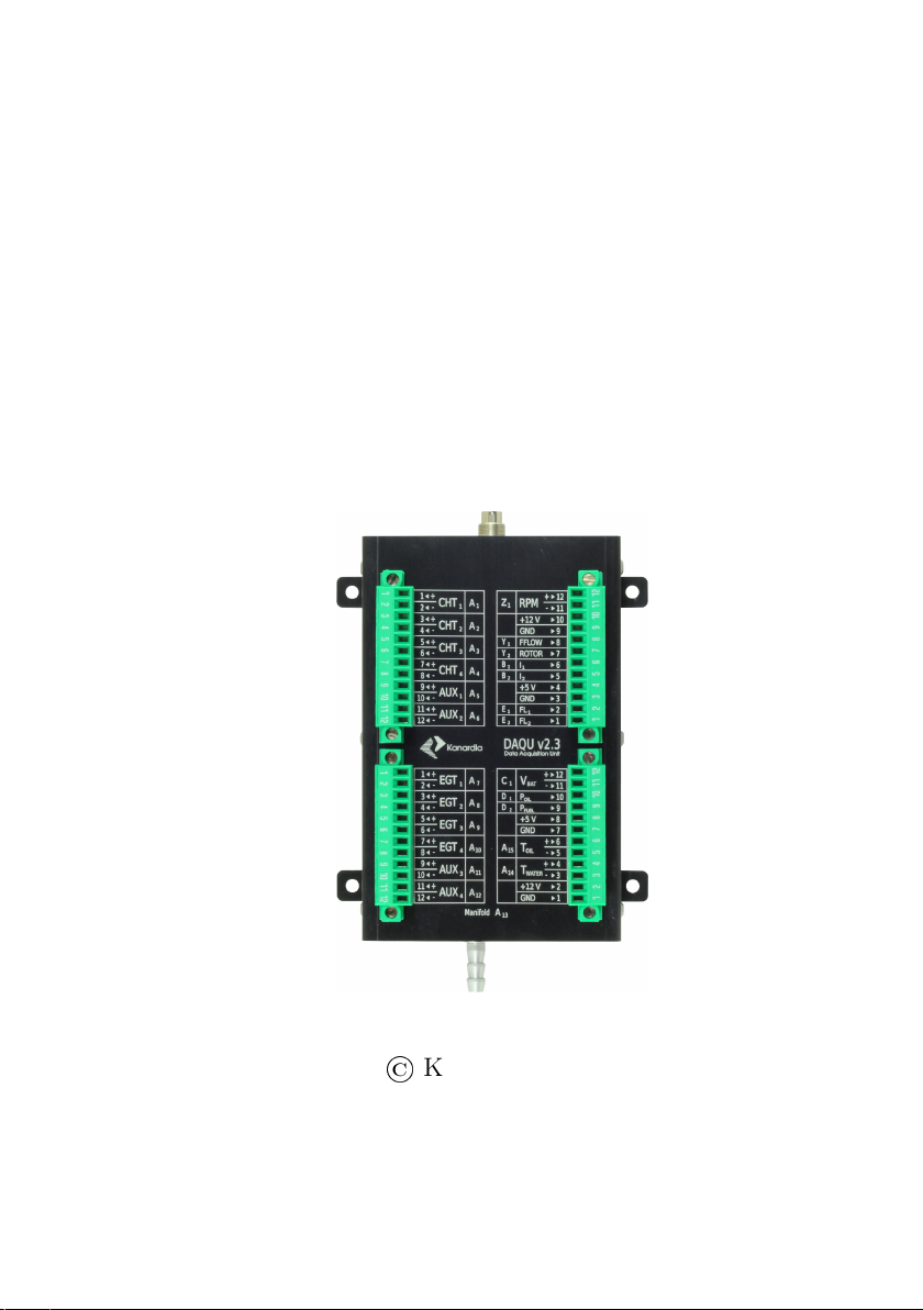
Daqu comes in two versions:
Standard, larger version is used for most engines: Rotax, Lycoming,
Continental, UL-Power, Simonini, Hirth, etc. Here, engine sensors are
directly connected to four twelve pin connectors. It also has one five pin
CAN connector and φ 5 mm outer diameter intake manifold pressure
connector.
Mini version a.k.a. Mini Daqu is used for some modern engines equipped
with digital output from their ECU. Here, most engine sensors are connected to ECU and mini Daqu simply reads sensor values from ECU
digital output. Besides information from ECU, mini Daqu allows connecting additional sensors like rotor RPM, fuel level, trim position, etc.
©
Kanardia 2019 6

Daqu — Manual 1.2 Channels
Mini Daqu is used with Rotax iS, D-motor, UL Power, Geiger wankel
and MW Fly engines. Mini Daqu has only one twelwe pin connector
for sensors and two D-SUB nine pin connectors – one for ECU and the
other for CAN network.
Optionaly, standard Daqu can be also modified to connect to engine ECU,
which effectively makes standard Daqu to act like a miniDaqu with mich more
input channels.
1.2 Channels
Daqu has digital type and analog type channels where each type has several
versions. Some channels are using two pins and some only one. They are
designated using capital letters.
1.2.1 Analog Channels
Most of the channels on Daqu are analog. They appear in following variations:
A – analog channels with -2.5 V to +2.5 V input. These channels are float-
ing – they are not connected with GND internally. They are typically
used to connect passive resistive sensors and thermocouples. Supported
resistive sensors are various VDO pressure sensors, most temperature
sensors, some fuel level sensors, trim potentiometers, etc. J and K type
thermocouples are supported.
B – analog channels with 0 to +5 V input. They are mostly used to read
active sensors. Active sensors require power in order to operate properly.
Do NOT connect any sensor with an output greater than +5 V. This
will permanently damage the unit.
C – analog channel with 0 to +30 V input, used to read higher voltage levels.
Only one such channel is available and is used to measure the system
voltage.
D – This is the same as B channel, but with additional internal 120 Ω
resistor. This allows connecting sensors with current output (4 mA –
40 mA). Rotax oil pressure is an example of such a sensor.
7
©
Kanardia 2019

1.3 Technical Specifications Daqu — Manual
E – This is the same as B channel, but with stronger current generator. This
generator is used when the channel measures resistance in low resitance
range. The following currents are used to measure resistance. In all
cases, the voltage difference is limited to 0-5 V.
for 0–200 Ω range – 20 mA current,
for 0–400 Ω range – 10 mA current,
for 0–1000 Ω range – 5 mA current.
They are typically used to connect resistive fuel level sensors and this
solves many contact problems, which appear when A channel used for
the same purpose.
1.2.2 Digital Channels
The digital channels are used to measure time between pulses. Typical sensors
connected to digital channels are engine RPM, rotor RPM and fuel flow. There
are two types of digital channels used in Daqu.
Z – is used to measure engine RPM. This channel has a special signal nor-
malizing circuit. Different engines have a very different signal levels. For
example, Rotax has up to 400 V (peak to peak) and Jabiru down to 1 V
(peak to peak). The circuit brings these different levels to a common
denominator. The circuit is able to process from 1.25 to 1000 pulses
per second. The upper limit equals to 20 pulses per revolution at 3000
PRM or 10 pulses at 6000 RPM. On lower end this equals to 75 RPM
at one pulse per revolution, 37.5 RPM at two pulses per revolution and
7.5 RPM at 10 pulses per revolution.
Y – is used for signals with nicer shape and voltage level, like rotor RPM
sensors, fuel flow sensors, etc. Time between signals and sometimes duty
cycle is measured. The signal voltage can be in 0-30 V range. From 1.25
to 1000 pulses per second can be processed.
More details and examples of channel use are given in forthcoming chapters.
1.3 Technical Specifications
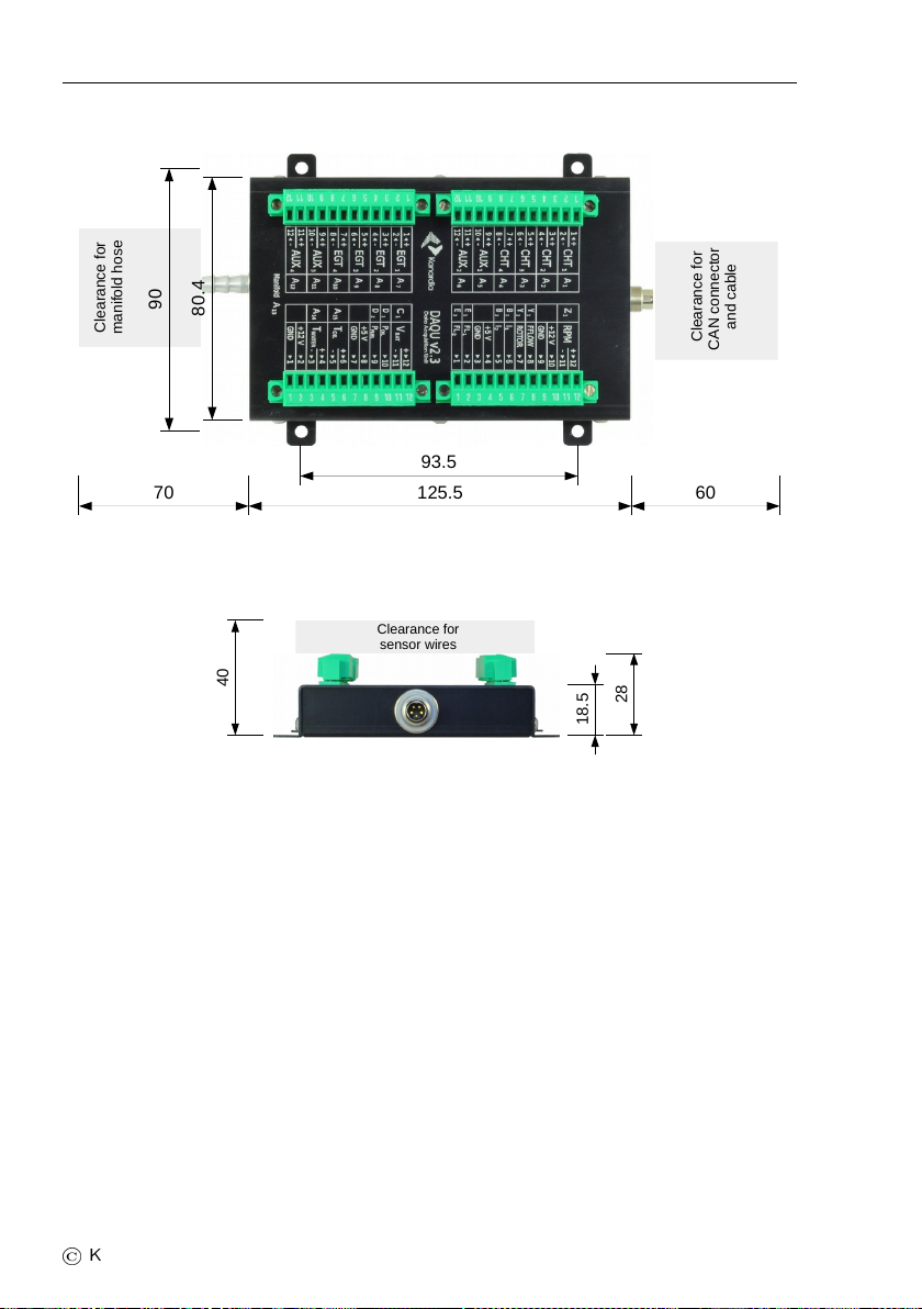
Table 1 lists technical specifications and figures 1 and 2 shows principal dimensions of Daqu.
©
Kanardia 2019 8

Daqu — Manual 1.3 Technical Specifications
Daqu has two connectors on opposite sides. One is used to connect manifold pressure hose and the other is used to connect CAN bus cable. Both
connectors require some additional clearence.
Four removable connectors on top are used to connect sensors. Some minimal
wire clearance is required, too.
Table 1: Technical specifications for standard Daqu.
Description Value
Weight 170 g
Size 125x80x20 mm (LxWxH)
Operational voltage 7–32 V
Current (sensors not connected) 60 mA at 12 V
Typical current (sensors connected) 100 mA at 12 V
Operating temperature –20◦C to +85◦C
Humidity 30% to 90%, non condensing
Max current load of 5V power source 150 mA
(both sources together)
Max current load of 12V power source 150 mA
(both sources together)
Digital channels 3: (1xZ, 2xY)
Analog channels 22: (15xA, 2xB, 1xC, 2xD, 2xE)
Processor Cortex M3, 60 MHz
Communication CAN bus, Kanardia protocol
Connector Binder 99 0414 00 05 (cable side)
9
©
Kanardia 2019
2. Installation Daqu — Manual
125.5
93.5
80.4
90
Clearance for
CAN connector
and cable
Clearance for
manifold hose
70 60
Clearance for
sensor wires
18.5
28
40
Figure 1: Dimensions and connection clearence of standard Daqu – Top View.
Figure 2: Dimensions and connection clearence of standard Daqu – Front
View.
2 Installation
This section reveals details about Daqu mechanical installation and main
connectors. It does not tell much about configuration and installation of
sensors, probes and transducers. A separate section with general principles
starts on page 13 and practical examples section starts on page 23.
2.1 General Rules
Daqu shall be installed close to the engine in order to keep the sensor cables
short. This can save significant weight on cables.
©
Kanardia 2019 10

Daqu — Manual 2.2 Intake Manifold Pressure
It may be installed on the engine side of the firewall providing that it is not
under direct influence of engine and/or exhaust heat.
The orientation or position of Daqu is not critical. Just make sure that Daqu
connectors are easily accessible and sensor cables are guided properly. A good
access to sensor connectors significantly simplifies the wiring, troubleshooting,
service and maintenance.
Daqu must NOT be mounted directly on the motor or on a place where
significant vibrations may occur.
Daqu is not waterproof. Significant measures were made to protect Daqu
electronics from moisture, but direct contact with fluid will cause invalid
sensor readings or even permanent failure. Make sure that Daqu will not
be exposed to fluids or moisture. Do not put Daqu under coolant expansion
bottle.
Please consider that flying trough rain delivers vast amount of water into
engine compartment. If Daqu is in engine compartment, please make sure
that this water will not reach it. If you intent to fly trough rain, the best way
is to enclose Daqu within some watertight compartment.
Daqu is not shipped with the mounting hardware. Any appropriate removable
fittings may be used. Do not rivet it in place.
2.2 Intake Manifold Pressure
Daqu has a built in MEMS pressure sensor that is used to measure the intake
manifold pressure.
Use a φ 5 mm inner diameter tube to connect the manifold pressure engine
source with the Daqu manifold connector. Secure the tube on all connections
using pipe clamps. Please, consult engine manual to locate the source of the
manifold pressure. On most engines a the protection cap and the protection
nipple first shall be removed first.
Installing a flow restrictor is higly recommended. This is an element with a
small hole in the middle, which allows the pressure to pass, but limits amount
of air that can go trough. Install the restrictor as close to the manifold
pressure source as possible. This is mostly due to the safety reasons. If tube
slips from Daqu or if internal tube inside Daqu leaks, the restrictor prevents
pressure change in the intake manifold.
11
©
Kanardia 2019
2.3 Connectors and Cables Daqu — Manual
+12V
GND
15
N/C or
Shield
CAN
high
CAN
low
A
A
A-A
B
B
B-B
+12VGND
CAN
low
CAN
high
2.3 Connectors and Cables
Power and CAN bus connector details are presented in this section. Sensor
connectors are described in a separate chapter.
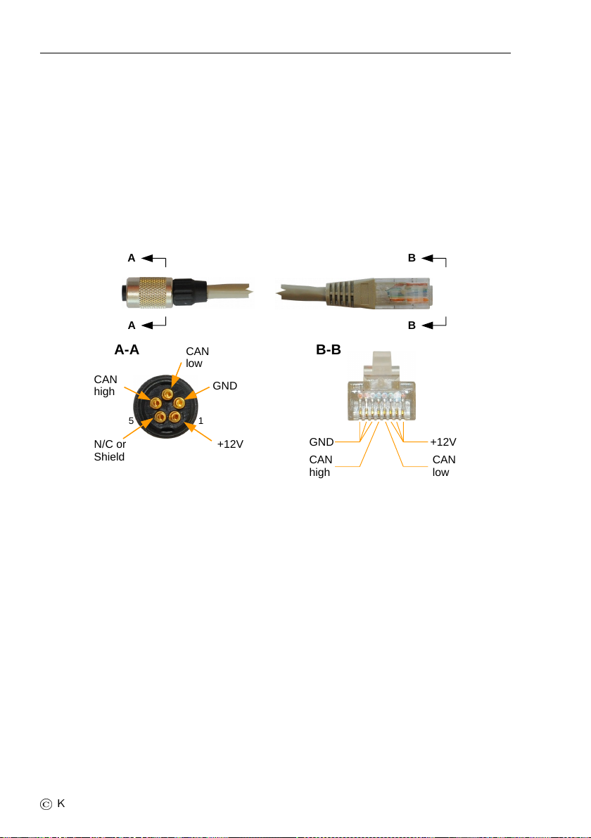
2.3.1 CAN Bus Cable
Standard Daqu has a five pin Binder connector, which connects Daqu to the
CAN bus system. Figure 3 illustrates the pins on the cable side.
Figure 3: Details of the cable connecting Daqu and other devices. Binder
connector is on the left and RJ45 connector is on the right. Binder
connector is shown from the soldering side. On the soldering part,
small numbers 1 and 5 are visible. RJ45 connector is shown from
front.
Only four pins (sometimes five) are used on Binder connector, while RJ45
connector uses all eight pins. On RJ45, three pins are used for GND, one
for CAN high, one for CAN low and the remaining three pins for +12V. This
means that three leads for GND must be soldered together to one GND pin on
Binder. The same is true for three +12V leads. This requires some patience
and skill. The fifth pin on Binder is connected to cable shield, when such
shielded cable is used. In majority of cases, shielded cable is not necessary.
Binder part numbers on the cable side are 99-0096-100-05 and 99-0414-00-05.
These two are equivalent. The connector on the housing has part number
09-0415-00-05.
©
Kanardia 2019 12
Daqu — Manual 3. Wiring in General
Standard cable length supplied with Daqu is 1.5 m (4.9 feet). A different
length may be also provided without any additional costs, when such length
is specified at the time of the order.
3 Wiring in General
This section reveals some basic principles of correct wiring. Not all options
are described, just the most common ones. The schematics presented in this
section shall be considered as general wiring guideline rather than a recipe.
There are also other sensors that Daqu can make use of and are not described
here.
When a problem is encountered, contact Kanardia and we will try to provide
you with a solution.
Check sensor manual and specifications before wiring and installing the sensor.
Follow the sensor instructions. Make sure that the wires are secured and they
will not get loose due to vibrations.
3.1 Connection Wires
Tefzel (or similar grade insulation) is recommended for all wires. The signal
wires thickness shall be AWG 22 unless other thickness is recommended.
3.2 Daqu Ground Pin (GND)
NEVER connect any Daqu ground pin (GND) directly to the aircraft or engine
block or to common system ground. Routing ground through aircraft/engine
block will not damage Daqu, but will create unnecessary ground loops, which
in turn may cause incorrect readings from the engine sensors, especially resistive ones.
Daqu ground pin should be used only when:
1. An active sensor is installed and GND pin is used together with some
+5/+12 V power pin to power the sensor and sensor signal is connected
to one of B, D, E or Y channels.
2. Isolated resistive (two wire) sensor is installed and GND pin is used as
a reference ground for the sensor. In this case sensor is connected to
some A or E channel.
13
©
Kanardia 2019

3.3 Resistive Sensors on A Channels Daqu — Manual
Special caution should be applied when dealing with fuel level sensors. If they
are resistive type, they should be connected to E channel.
3.3 Resistive Sensors on A Channels
Resistive sensors are often used for various temperature probes, pressure sensors, fuel level probes, trim positions, etc. The resistive sensors can be connected either to A or to E channels. The principles are a bit different regarding
to the channel type used. This section describes connection to A channels and
section 3.4 describes connection to E channels.
For A channels, two basic schematics can be used, based on the sensor type.
One wire sensors have slightly simpler schematics, but they are more
sensitive to ground loops. When a large current consumer is turned on,
sensor values may jump a bit, sometimes they may even go crazy.
Two wire sensors have slightly more complex schematics, but they are
less susceptible towards large currents.
3.3.1 One Wire Sensors
Some sensors connect with only with one wire. The wire is connected to + pin
of A channel. Although it seems that there is no second wire, in fact it is.
The “invisible” ground wire is provided by the engine block. This means that
negative terminals of selected A channel must be connected to the engine
block, which acts as a second wire.
Figure 4 illustrates such situation for two resistive sensors. A thick ground
wire (use AWG 17 or less) must be routed directly from the engine block
close to Daqu, where it is split and connected to negative terminals of one
wire resistive sensors.
In theory, any system ground point could be used to connect the negative
terminals. In practice this is causing problems (ground loops) and taking
ground directly from the engine block and splitting this ground close to terminals works the best.
There may be several one-wire resistive sensors connected to Daqu. Figure
5 illustrates situation where two CHT, one oil temperature and one resistive
oil pressure sensors are connected. They all are one wire sensors and all are
grounded via engine block. The engine block is connected with one AWG 17
wire, which leads to the splitter and from the splitter separate wires lead to
each negative terminal.
©
Kanardia 2019 14
 Loading...