

Page 1
M-Bus
Technical Description
Kamstrup A/S
Industrivej 28, Stilling
DK-8660 Skanderborg
TEL: +45 89 93 10 00
FAX: +45 89 93 10 01
info@kamstrup.com
www.kamstrup.com
Page 2

Contents
1. Technical description M-Bus 3
Introduction 3
2. M-Bus System 4
M-Bus system components 4
Communication 4
Addresses of M-Bus Slave units 4
Primary addressing 4
Secondary addressing 4
Operation 5
3. M-Bus Master 6
®
4. M-Bus Slave for MULTICAL
5. M-Bus Slave for MULTICAL® Compact/MULTICAL® 401 8
6. M-Bus Slave for Kamstrup 162/382/351 Combi 9
7. M-Bus Cascade module 10
7
8. M-Bus Modem 12
Test 12
9. Installation of M-Bus 13
Cable length 13
Mounting 13
10. Data reading of M-Bus 15
Data reading of heat meters 15
®
M-Bus Slave for MULTICAL
III/MULTICAL® 15
M-Bus Slave for MULTICAL® Compact/MULTICAL® 401 16
Data reading of Kamstrup 162/382/351 Combi 16
M-Bus Slave for Kamstrup 162/382/351 Combi 16
Reading equipment 16
11. Protocol 17
Commands 17
The individual commands in detail 17
M-Bus Master to M-Bus Slave 17
M-Bus Slave to M-Bus Master 18
Communication process 19
Reading of fresh data through e.g. data logging 20
M-Bus Slave and foreign M-Bus masters 20
Appendix 20
Physical properties 26
5511-710 GB/12.2004/Rev. C1
2
Page 3
1. Technical description M-Bus
Introduction
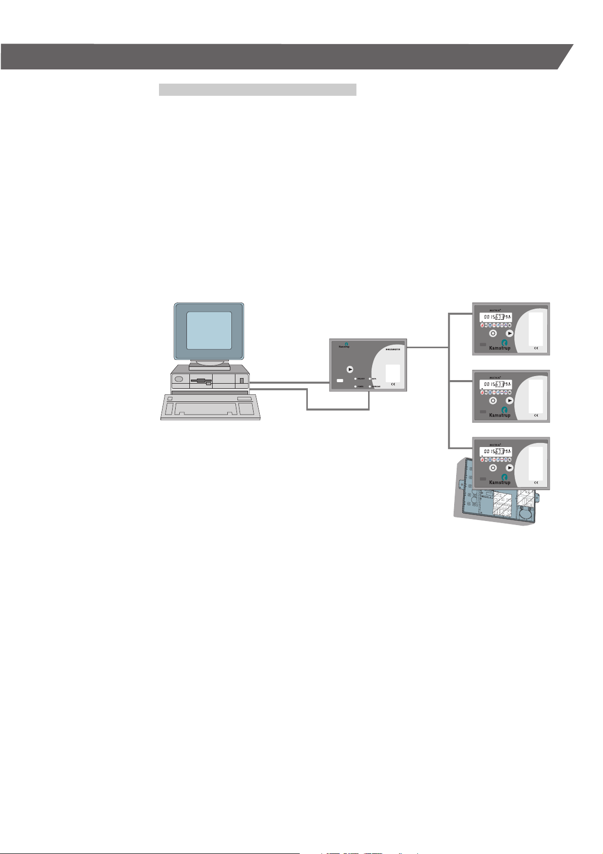
This document describes the use of Kamstrup’s
M-Bus system.
M-Bus is used for electronic reading of district heat
meters.
As the data route from meter to accounting
program is electronic, the data is secured against
errors. It is easy and simple to equip Kamstrup
energy meters with an M-Bus Slave, which is
inserted at the modular space in the energy meter.
It is unnecessary to program the integrating energy
meter or the M-Bus Slave as the system is selfconfiguring.
M-Bus Master
Computer placed
at the utility
5511-710 GB/12.2004/Rev. C1
Heat meters with
M-Bus Slave
3
Page 4

2. M-Bus System
M-Bus system components
The M-Bus system consists of the following
elements:
M-Bus Slave
■
M-Bus Master
■
M-Bus Cascade module
■
M-Bus Modem
■
Communication software PcM-Bus
■
Communication software PcModem
■
Communication software PcLink
■
IR head for reading
■
■
Data cabel for reading
The M-Bus Master is built-up as a repeater, which
converts signals from e.g. RS232 to M-Bus format
(18-30 V/0-20 mA). The M-Bus Master has been
constructed to function together with Kamstrup’s
M-Bus Slaves and Kamstrup’s reading software.
The M-Bus Master can supply up to 40 M-Bus
Slaves at the power consumption of 1.5 mA
(1 Unit Load) per M-Bus Slave.
One or more M-Bus Cascade modules can be installed, and can comprise up to 250 M-Bus Slaves.
Communication
The communication on the M-Bus consists of
vol-tage modulation from M-Bus Master to M-Bus
Slave (30 – 18 V) as well as current modulation
from M-Bus Slave to M-Bus Master (0 – 20 mA)
through an ordinary two-wire cable.
The M-Bus system has been constructed to observe
the regulations of the EN 1434-3.
The communication on the M-Bus system is asynchronous serial bit transmission (EN 60870-5-1)
in half duplex mode, i.e. the communication consists of 1 start bit, 8 data bits, 1 parity bit (even),
1 stop bit.
The transmission speeds are 300 baud or 2400
baud.
Addresses of M-Bus Slave units
If the M-Bus system is to function with a number
of connected M-Bus Slaves, each M-Bus Slave
must be given an identification number (address).
This is done via MULTICAL
®
, which contains a
unique customer number to the M-Bus Slave. The
unique address of the M-Bus Slave is equal to the
last 3–8 digits of the customer number, and thereby supports both primary and secondary addressing. The address applies to both types of addressing, and can be re-programmed either by means
of the hand-held terminal, MULTITERM, or the verification program of METERTOOL.
Primary addressing
The M-Bus Slave automatically reads the energy
meter’s costumer number in connection with start
or initialisation. The address must lie between 1
and 250.
If the last three digits of the customer number
exceed 250 (e.g. 345) the first digit will be ignored
and the ID number of the M-Bus Slave will only be
determined by the two last digits (e.g. 45).
If 3 systems are available each with 250 M-Bus
Slave modules, the number system is build up as
follows:
1st. system:
The energy meters are programmed with customer
numbers from 1001 to 1250.
2nd. system:
The energy meters are programmed with customer
numbers from 2001 to 2250.
3rd. system:
The energy meters are programmed with customer
numbers from 3001 to 3250.
Secondary addressing
The M-Bus Slave automatically reads the customer
number of the energy meter during start or initialization.
The M-Bus address consists of the last 3 – 8 digits
of the customer number, extending the address
possibility to 0000 0001 – 9999 9999.
Note: Kamstrup communication software,
PcM-Bus, and Kamstrup M-Bus Master
do not support secondary addressing.
The M-Bus module does not support extended
secondary address functions, e.g. enhanced secondary addressing, collision detection or wild-card
search.
Each M-Bus Slave must have its own addres
The M-Bus Master always sends a message on the
bus to a given address, which is encoded in the
message (the format). Only the M-Bus Slave in question will reply.
If several M-Bus Slaves have the same address a
collision will arise, when the M-Bus Slaves reply to
the M-Bus Master.
However, there are two special addresses, which
function as follows:
Address 254:
All M-Bus Slaves will answer to this address. The
address must solely be used in systems with only
one M-Bus Slave connected, e.g. for test.
Address 255:
No M-Bus Slave will answer to this address, but
all M-Bus Slaves will receive the message. This
message makes it possible e.g. to change the baud
rate of a whole system at a time, only by sending a
format from the M-Bus Master.
5511-710 GB/12.2004/Rev. C1
4
Page 5

Operation
It is optional whether the M-Bus Master is to be
permanently switched on, or the bus system is to
be switched off when not in operation (reading).
The M-Bus system cannot supply the MULTICAL
®
integrating units. Only the M-Bus Slaves are supplied from the M-Bus Master.
In connection with start-up the M-Bus Master will
have an initialization time of approx. 5 sec., and
the overload diode will light. After the 5 sec., the
diode will switch off and the M-Bus Master is ready.
In case the bus system is turned on constantly,
these initialization times will only appear in connection with installation. In addition, the initialization
time of M-Bus Slaves is approx. 9 sec., before data
can be acquired, and if mounted in MULTICAL
®
III.
However, if the M-Bus Slaves are installed in
®
MULTICAL
the initialization time is approx. 12 sec.
The initiation time for Kamstrup 162/382/351 Combi
is typically 7 seconds.
Rarely, a longer initiation time might be necessary
– see Appendix.
5511-710 GB/12.2004/Rev. C1
5
Page 6
3. M-Bus Master
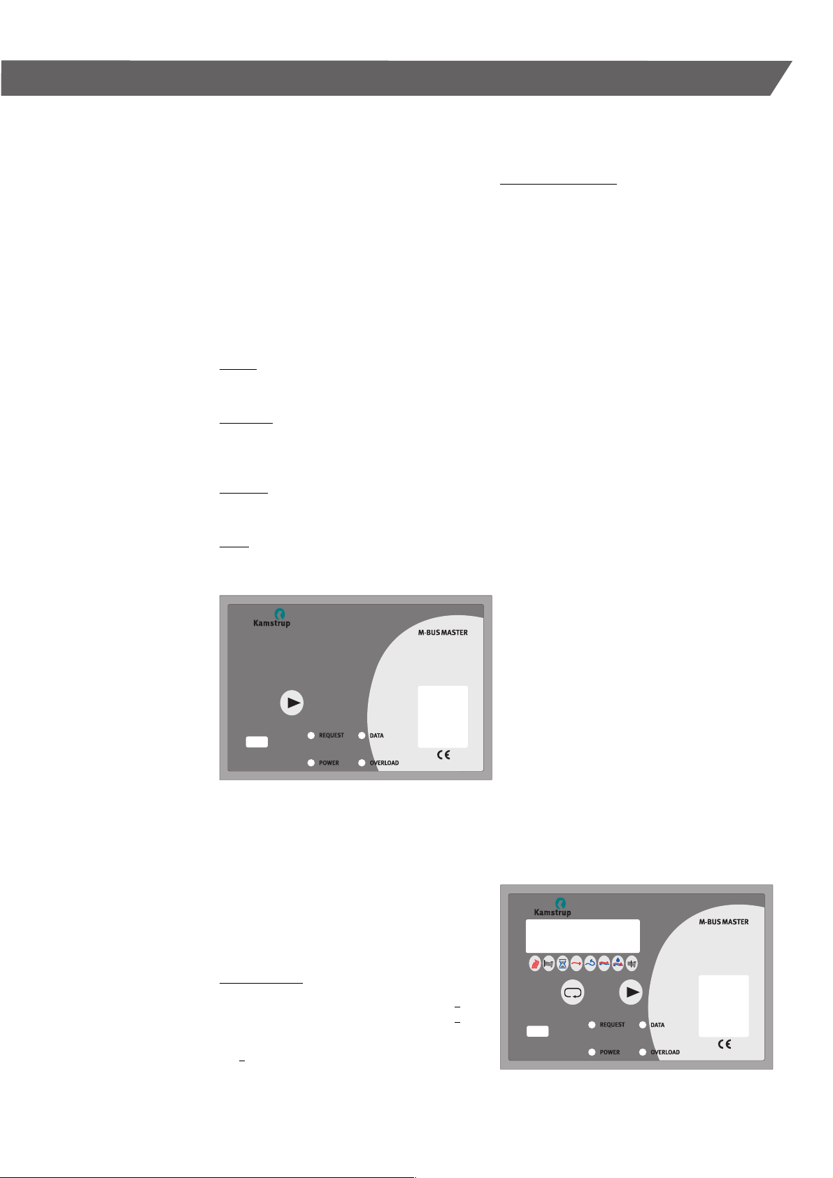
Two versions of the M-Bus Master are available.
One with a display and one without, however,
they function in the same way.
The M-Bus Master is built-up with supply print,
connection print and main print.
Furthermore the bracket has room for an extra
module – see paragraph 7 and 8.
The main print is placed at the top of the case,
and except from transformator, bridge connection
and connection terminals everything is mounted
on this print.
The front plate has four light emitting diodes
with the following indications:
Power:
Indicates that the M-Bus Master is supplied
with power.
Overload:
Indicates that too much power is drawn from the
bus. I.e. either a short-circuit or too many M-Bus
Slaves connected to the M-Bus Master.
Request:
Blinks when data are sent from M-Bus Master
to M-Bus Slave.
Data:
Blinks when the M-Bus Master receives data
from a M-Bus Slave.
M-Bus Master without display
The M-Bus Master is no intelligent unit, but a
repeater, which converts a RS232 or an optical
format to the M-Bus format.
M-Bus format means:
From M-Bus Master to M-Bus Slave is:
mark » 30 V
space » 18 V
There has to be at least 12 VDC between mark
and space.
From M-Bus Slave to M-Bus Master is:
mark = closed current
space = closed current + approx. 17 mA.
The M-Bus Master can send and receive at 300 or
2400 baud both over the optical connection possibility and over the data output in the bracket which
can be connected direct to RS232 by means of an
adapter cable.
The only difference between the two M-Bus
Masters is that M-Bus Master with a display makes
it possible to read data from all MULTICAL
meters connected, and a computer for reading of
data is not necessary.
Following MULTICAL
on the display:
1. For all heat meters
- Info code
- Energy
- Volume
- In A
- In B
- Target date
2. For each individual heat meter
- Target energy
- Target volume
- Flow temperature
- Return temperature
- ∆t, power and flow
Kamstrup M-Bus Masters can only be used with
primary addressing.
For further information – see the M-Bus Master
manual.
®
heat meter data can be read
®
heat
5511-710 GB/12.2004/Rev. C1
Ordernumbers:
M-Bus Master without display 66-98-11x-xxx
M-Bus Master with display 66-98-A1x-xxx
M-Bus Master manual 5511-185
x = module options (see paragraph 7 and 8)
xxx = Country code – is filled in by
Kamstrup A/S.
M-Bus Master with display
6
Page 7
4. M-Bus Slave for MULTICAL
®
The M-Bus Slave is a module especially developed
for MULTICAL® and is easily installed in the modular space.
The M-Bus Slave is supplied via the M-Bus Master,
and there is a galvanic decoupling to MULTICAL
®
,
which cannot be supplied over the M-Bus Master.
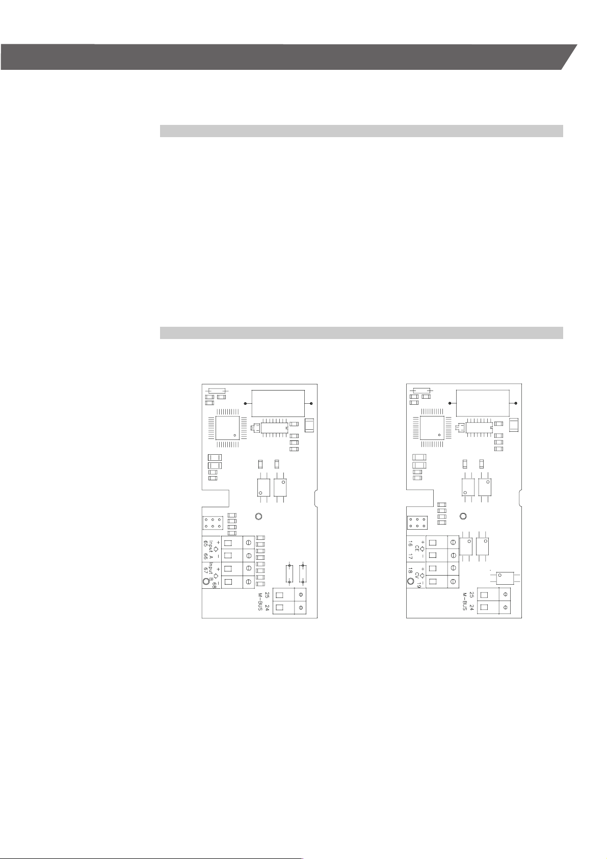
The M-Bus Slave is equipped with either two
extra in- or outputs, to facilitate remote data
acquisition from other meters, e.g. water meter
or to read out the energy and volumes pulses
from the meter itself.
The M-Bus Slave is an intelligent unit with its own
processor and RAM.
The M-Bus Slave automatically collects data from
the heat meter every 12 hours. furthermore data is
collected during reset/start as well as when data
has been sent from M-Bus Slave to M-Bus Master.
Reset is produced by decoupling the supply power
to the M-Bus system for a while (at least 1 minute).
Pulse inputs Pulse outputs
The M-Bus Slave can also be initiated from the
M-Bus Master by sending the format SND_NKE.
Initiation means resetting the internal counters
and collecting data from the meter. When the M-Bus
Slave collects current data from the meter, communication to the M-Bus network is blocked. This interval is called the initiation time, for MULTICAL
®
III it
is typically 9 seconds, whereas the typical initiation
time of a MULTICAL
®
is 12 seconds.
For the creation of M-Bus data packs the M-Bus
Slave uses the codings of MULTICAL
®
(A-B-CCC).
If the coding cannot be found in the M-Bus Slave
an error message appears which means that the
decimal point will not be correctly placed in the
M-Bus data pack.
Each M-Bus Slave has a maximum current
consumption of 1 Unit Load (1.5 mA).
R
= 410 Ω, Cin = 0,5 nF.
in
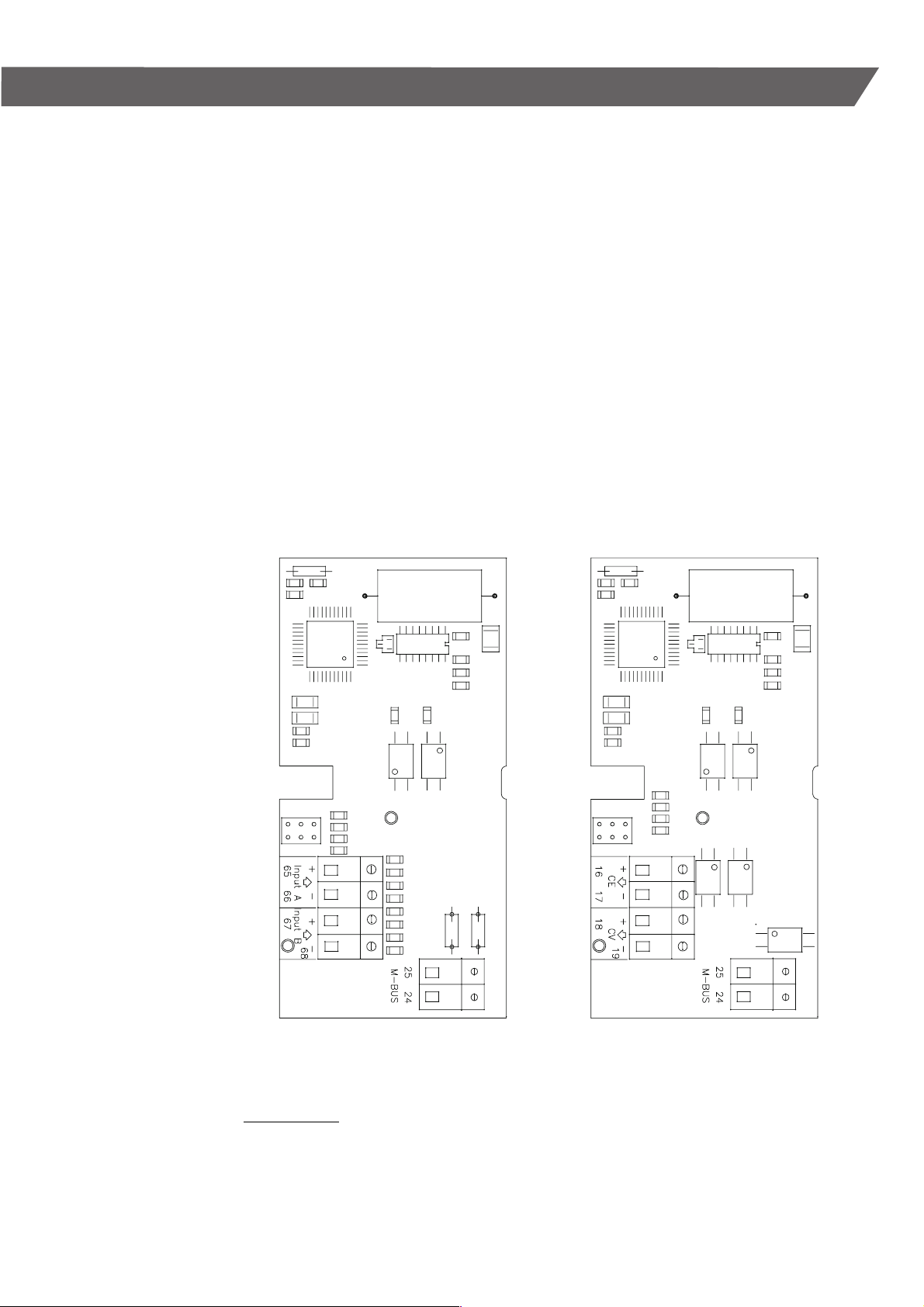
Terminal 24-25 (M-Bus) M-Bus connection
Terminal 65-66 (input A) Pulse input A
Terminal 67-68 (Input B) Pulse input B
Terminal 24-25 (M-Bus) M-Bus connection
Terminal 16-17 (CE) Energy pulse
Terminal 67-68 (CV) Volume pulse
Order numbers:
M-Bus Slave for MULTICAL
M-Bus Slave for MULTICAL
M-Bus Slave for MULTICAL
M-Bus Slave for MULTICAL
®
III/MULTICAL® with pulse inputs 66-04-000-100
®
III/MULTICAL® with pulse outputs 66-07-000-100
®
with pulse inputs 66-08-000-100
®
with pulse outputs 66-09-000-100
There is a difference between the M-Bus Slaves for MULTICAL
MULTICAL
®
transmits a larger amount of data. Please refer to paragraph 10: Data acquisition of M-Bus.
®
III and MULTICAL®.
5511-710 GB/12.2004/Rev. C1
7
Page 8

5. M-Bus Slave for MULTICAL® Compact/MULTICAL® 401
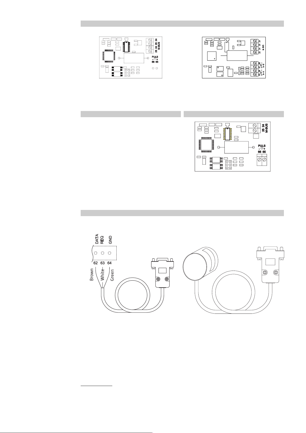
M-Bus for MULTICAL
Terminal 24-25 (M-Bus) Connections
Terminal 65-66 (Pulse) Not in use
Display Battery
Module area
Module area in MULTICAL
Display Battery
®
Compact/MULTICAL® 401
®
Compact
The M-Bus Slave is a module especially developed
for MULTICAL® Compact/MULTICAL® 401, and is
easily installed in the module area.
The M-Bus Slave is an intelligent unit with a
processor and RAM of its own.
The M-Bus Slave for MULTICAL
MULTICAL
MULTICAL
®
401 is identical with the one for
®
III, except from the physical dimensions.
®
Compact/
There are two versions of the M-Bus module:
– without pulse inputs
– with pulse inputs
Both modules can be used in MULTICAL
as well as MULTICAL
®
401, however, the pulse in-
puts can only be used together with MULTICAL
®
Compact
®
401.
Each M-Bus Slave has a max. power consumption
of 1 Unit Load (1.5 mA)
R
= 410 Ω, Cin = 0,5 nF.
in
Data is automatically read every 12 hour, furthermore data is collected during reset/start as well
as when data has been sent from M-Bus Slave to
M-Bus Master. Reset is produced by decoupling
the supply power to the M-Bus system for a while
(at least 1 minute).
The M-Bus Slave can also be initiated from the
M-Bus Master by sending the format SND_NKE.
Initiation means resetting the internal counters
and collecting data from the meter.
When the M-Bus Slave collects current data from
the meter, communication to the M-Bus network
is blocked. This interval is called the initiation
time, for MULTICAL
®
Compact/MULTICAL® 401 it
is typically 9 seconds.
See Appendix for further information.
5511-710 GB/12.2004/Rev. C1
Module area
Module area in MULTICAL
Order numbers:
M-Bus Slave for MULTICAL
M-Bus Slave for MULTICAL
M-Bus, pulse inputs for
®
401
®
Compact/MULTICAL® 401 66-0S-000-100
®
Compact/MULTICAL® 401 with pulse inputs 66-0S-000-200
MULTICAL
®
Compact/MULTICAL® 401
8
Page 9

6. M-Bus Slave for Kamstrup 162/382/351 Combi
The M-Bus Slave is especially developed for
Kamstrup 162/382/351 Combi, and is easily
installed in the modular space of the electricity
meter.
The M-Bus Slave for electricity meters is equipped
with a pulse input.
Terminal 24-25 (M-Bus) Connections
Terminal 65-66 (Pulse) Pulse input
The physical dimensions are identical with those of
the M-Bus Slave for MULTICAL
it cannot be used for a MULTICAL
The M-Bus Slave is an intelligent unit with a processor and RAM of its own, and it automatically finds
out in which meter type it is placed.
Data is automatically read every hour, furthermore
data is collected during reset/start as well as when
data has been sent from M-Bus Slave to M-Bus
Master. Reset is produced by decoupling the supply
power to the M-Bus system for a while (at least 1
minute).
The M-Bus Slave can also be initiated from the
M-Bus Master by sending the format SND_NKE.
Initiation means resetting the internal counters
and collecting data from the meter.
When the M-Bus Slave collects current data from
the meter, communication to the M-Bus network
is blocked. This interval is called the initiation time,
and is for Kamstrup 162/382/351 COMbi typical
7 seconds.
See Appendix for further information.
The power consumption of each M-Bus Slave
is 1 Unit Load (1.5 mA).
R
= 410 Ω, Cin = 0,5 nF.
in
®
Compact, however,
®
Compact.
5511-710 GB/12.2004/Rev. C1
M-Bus Slave mounted
in an electricity meter
Order numbers:
M-Bus Slave for Kamstrup 162/382/351 Combi 6850-005
9
Page 10

7. M-Bus Cascade module
The M-Bus Cascade module can be used to increase
the number of M-Bus Slaves in an M-Bus network
from 40 to max. 250 M-Bus Slaves (primarily
addressing). Furthermore, the cable length can be
multiplied by six by using six M-Bus Cascade
modules mounted in M-Bus Master units.
The M-Bus Cascade module is mounted in an M-Bus
Master and needs neither set-up nor address.
The function of the M-Bus Cascade module is
to repeat communication to and from the M-Bus
Master.
A new M-Bus Master with M-Bus Cascade module
is to be connected to an already existing network
®
parallel to one of the connected MULTICAL
energy
meters with M-Bus Slave. From the new M-Bus
Master a new network with 38 energy meters and
1 M-Bus Cascade module or 40 M-Bus Slaves can
be established.
It is possible to connect up to 6 M-Bus Masters
and thereby increase the number of energy meters
in the network to a total of 250 meters (primarily
addressing).
Each M-Bus Cascade module has a power
consumption of 2 Unit Loads (3 mA).
R
= 410 Ω, Cin = 0,5 nF.
in
Extra cable length per unit:
Max. 1.800 m to the most remote
M-Bus Slave/0.8 mm
2
.
M-Bus interface
(53, 54)
To this the
M-Bus Slaves
are connected.
Input A (65, 66),
Input B (67, 68).
– Are not in use.
.
5511-710 GB/12.2004/Rev. C1
10
Page 11

The number of M-Bus Slave modules/cable length as a function of the number of M-Bus Cascade units
in a Kamstrup M-Bus system.
M-Bus
Master
Cascade unit =
1 Cascade module
+ 1 M-Bus Master
Total numbers of M-Bus Slaves
Total cabel lenght
0,5/0,8 mm
1 0 40 1000/1800 m
1 38 + 40 = 78 2000/3600 m
2 38 + 38 + 40 = 116 3000/5400 m
3 38 + 38 + 38 + 40 = 154 4000/7200 m
4 38 + 38 + 38 + 38 + 40 = 192 5000/9000 m
5 38 + 38 + 38 + 38 + 38 + 40 = 230 6000/10800 m
6 38 + 38 + 38 + 38 + 38 + 38 + 22 = 250 7000/12600 m
2
5511-710 GB/12.2004/Rev. C1
Order numbers:
M-Bus Cascade module 66-98-001-100
1 = module number
11
Page 12

8. M-Bus Modem
An M-Bus system of up to 40 meters can be read
via the M-Bus Modem.
The M-Bus Modem can be mounted in both M-Bus
Master without a display and M-Bus Master with
a display.
The line voltage is measured here.
Test
1. When the modem has been installed, the line
voltage must be measured on clamps 70 and
71. It must be min. 24 VDC.
2. Remount the top of the M-Bus Master.
3. Make a forced call.
M-Bus Master without a display
Keep pressing the key for min. 10 seconds.
The modem module calls the utility at the
entered number.
M-Bus Master with display
Keep pressing both keys for min. 10 seconds,
until a “Call” appears in the display.
The modem module calls the utility at the entered number.
The M-Bus Modem is read via the communication
software PcModem, but uses the same database
as PcM-Bus.
When the call has been made, we recommend you
to call the utility to ensure that the call has been registered by the system software.
Two telephone numbers are entered into the
M-Bus Modem:
Telephone number 1: The data number for
■
remote reading.
Telephone number 2: An alternative data num-
■
ber for remote reading.
Each number can contain 24 digits.
The M-Bus Modem can be programmed to make
calls directly and not via a PABX switchboard according to the “0 - Pause - dialling tone” method.
For further information please refer to:
The M-Bus Master manual
■
The M-Bus Modem installation guide
■
The PcModem manual
■
5511-710 GB/12.2004/Rev. C1
Order numbers:
M-Bus Modem module 66-98-002-319
2 = module number
12
Page 13

9. Installation of M-Bus
An M-Bus system is mounted with bus topology,
which means that all M-Bus Slaves are coupled to
the M-Bus system in parallel. You start from the
M-Bus Master, into the first M-Bus Slave, from the
first M-Bus Slave and on to the next one etc.
The M-Bus Master has two sets of parallel terminals, which makes it possible to divide the M-Bus
in two halves in order to facilitate later error detection.
The M-Bus terminals have the numbers 24 and 25.
The M-Bus is independent of polarity i.e. it is at no
consequence how the M-Bus wires are connected
to terminals 24 or 25.
®
A M-Bus Slave is mounted in MULTICAL
ting the M-Bus Slave at the module place and
mounting the M-Bus cables. Before the identification number can be entered in the M-Bus Slave,
the M-Bus Slave must be either reset or initiated.
We recommend that the whole M-Bus system is
switched off when mounting new M-Bus Slaves.
When all M-Bus Slaves have been connected,
the M-Bus system is started (the current to the
M-Bus Master is switched on). This start will reset
all M-Bus Slaves.
by inser-
M-Bus Slaves can also be mounted without the
M-Bus system being switched off. This means that
SND_NKE must be sent to address 255 when all
M-Bus Slaves have been mounted in order to initiate them. Failing to do so, the connected M-Bus
Slaves will not collect their ID-numbers, so that
the M-Bus Master can contact them, until 12 hours
later.
Cable length
The cable length depends on the cable resistance
and capacity. The cable resistance depends on the
cable type and above all the cross section.
General demands:
The resistance R must be less
than 29 Ω/km.
The capacity C must be less
than 180 nF/km.
If e.g. a cable of 2 x 0.8 mm
approx 1.800 m cable is used in total in the M-Bus
system based on 40 M-Bus Slaves.
In addition – see tabel on page 11
2
is used, in practice
Mounting
M-Bus connection
Supply
Modular space for M-Bus Modem
or M-Bus Cascade module
5511-710 GB/12.2004/Rev. C1
Introduction of M-Bus
and data cable
Serial data output line 230 VAC Introduction of 230 VAC
Botton of the M-Bus Master
13
Page 14

230 VAC is connected on terminals 27 and 28.
Power supply is connected on terminals 60 (+)
and 61 (-).
M-Bus is connected on terminals 24 and 25,
independent on polarity.
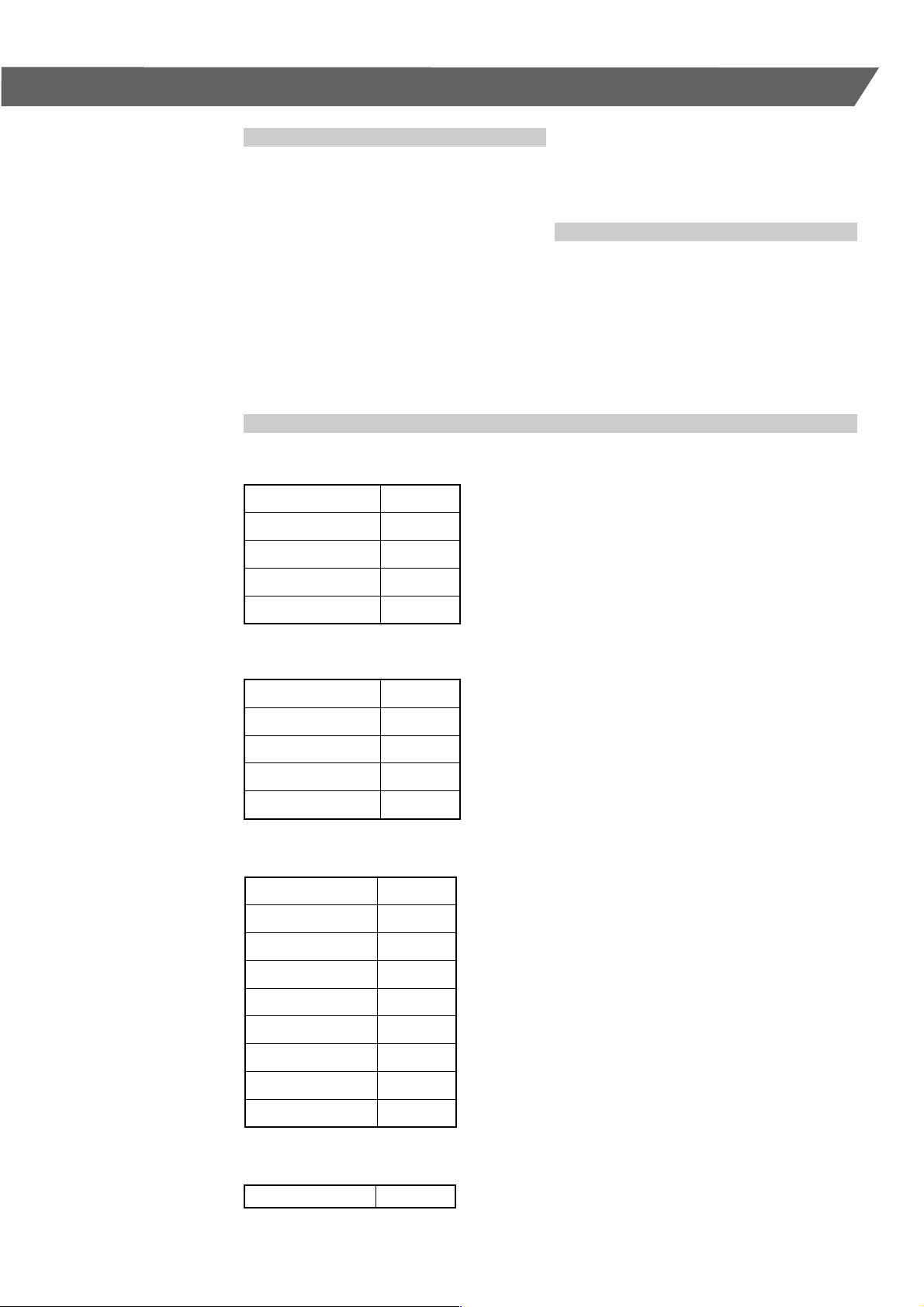
Serial data output:
- terminal 62 = DATA: Brown
- terminal 63 = REQUEST: White
- terminal 64 = GND: Green
For correct communication between M-Bus Master
and PC, IR head type 66-99-102 or data cable type
66-99-106 from Kamstrup must be used.
The M-Bus Slave is connected to M-Bus on terminals 24 and 25. It is possible to loop the terminals.
After mounting we recommend to check the voltage on terminals 60 and 61, it should be between
36 and 62 VDC. Then mount the M-Bus Master top
part, the light emitting diode designated POWER
should be constantly lighted and OVERLOAD will
be lighted for approx. 5 sec.
Now the M-Bus power can be checked on terminals
24 and 25. It is not possible, however, to do this in
the bracket itself, cables on which to measure must
be mounted and drawn through the bracket.
The control can possibly be made on a M-Bus Slave
in a MULTICAL
®
. The power must be between 30 and
36 VDC, if communication is made on the M-Bus.
When the M-Bus Master reads a M-Bus Slave,
REQUEST will be lighted briefly and the light emitting diode DATA will be lighted short-term when
the M-Bus Slave answers.
Extra pulse inputs M-Bus connection
M-Bus Slave for MULTICAL
®
III/MULTICAL
®
M-Bus connection Supply Serial data output
M-Bus cable
2-wire
E.g.: 2 x 0.8 mm
Max. 1800 m
Max. 40 M-Bus
Slave modules.
M-Bus Master
5511-710 GB/12.2004/Rev. C1
Holes 230 VAC
for cables
2
MULTICAL
M-Bus connection
M-Bus Slave
®
bottom
M-Bus connection
M-Bus Slave
MULTICAL
M-Bus installation
®
bottom
14
Page 15
10. Data reading of M-Bus
A Kamstrup M-Bus system is read by means of a
PcM-Bus reading programme installed on a PC.
Data reading of heat meters
Following data message can be read:
®
66-04-000-100 pulse inputs MULTICAL
66-07-000-100 pulse outputs MULTICAL
66-0S-000-100 MULTICAL
66-0S-000-200
pulse inputs MULTICAL® Compact/401:
®
Compact/401:
III/CDE
®
III/CDE
- Customer ID No., TA2, TL2, TA3, TL3, InA, InB,
Prog No., Config. No., Date, Energy, Volume,
Hour counter, t
forward
, t
, ∆t, Power, Flow,
return
Peak power or peak flow, Info Code, Target
date, Energy*, Volume*.
NB.: M-Bus Slave modules for MULTICAL
be used in MULTICAL
®
but in such cases it will only
®
III can
tranfer above data telegram. InA and InB are not
used in 66-07-000-100 or in 66-0S-000-100.
M-Bus Slave for MULTICAL® III/MULTICAL
®
Pulse inputs
66-04-000-100
66-08-000-100
Data is read via the M-Bus Master through the
IR-head, or via a data cable mounted in the bottom
of the M-Bus Master.
Following data message can be read:
6608-000-100 pulse inputs MULTICAL
66-09-000-100 pulse outputs MULTICAL
®
,
®
:
- Customer ID No., TA2, TL2, TA3, TL3, InA, InB,
Prog. No., Config. No., Date, Energy, Volume,
Hour counter, t
Peak power or peak flow, Info Code, m
3
m
x t
, Cooling energy, Yearly peak power,
return
forward
, t
, ∆t, Power, Flow,
return
3
x t
forward
Target date, Energy*, Volume*.
NB.: Can only be used in MULTICAL
®
.
InA and InB are not used in 66-09-000-100.
* Target date data
Pulse outputs
66-07-000-100
66-09-000-100
,
Terminal 24-25 (M-Bus) M-Bus connection
Terminal 65-66 (Input A) Pulse input A
Terminal 67-68 (Input B) Pulse input B
5511-710 GB/12.2004/Rev. C1
Terminal 24-25 (M-Bus) M-Bus connection
Terminal 16-17 (CE) Energy pulse
Terminal 18-19 (CV) Volume pulse
15
Page 16
M-Bus Slave for MULTICAL® Compact/MULTICAL® 401
Without pulse inputs With pulse inputs
Terminal 24-25 (M-Bus) M-Bus connection
Terminal 65-66 (In A) Pulse input A Not in use for MULTICAL
Terminal 67–68 (In B) Pulse input B Not in use for MULTICAL
Data reading of Kamstrup 162/382/351 Combi
M-Bus Slave for Kamstrup 162/382/351 Combi
Following data telegram can be read:
162/282/382:
- Energy, Power, Operating hours, Counter value,
Peak power, Customer number, Pulse input,
Spec. data, Info Code.
351 Combi:
- Customer number, Operating hours, True
energy, Power, Peak power, Pulse input,
Spec. data, Info Code.
Terminal 24-25 (M-Bus) M-Bus connection
Terminal 65-66 (Pulse) Pulse input
See the PcM-Bus manual for further information.
Reading equipment
Data cable for reading IR head for reading
®
Compact
®
Compact
Data cable or IR head must be used for correct transmission of meter data between M-Bus Master and PC.
Order numbers:
M-Bus Software PcM-Bus S75-30-007
PcM-Bus manual 5511-722
IR head for reading 66-99-102
Cable for reading 66-99-106
5511-710 GB/12.2004/Rev. C1
16
Page 17
11. Protocol
Commands
The M-Bus concept includes the possibility of
various commands from M-Bus Master to M-Bus
Slave and from M-Bus Slave to M-Bus Master.
For the Kamstrup M-Bus system certain commands
which are relevant for the communication with a
district heat meter have been chosen.
M-Bus Master to M-Bus Slave:
REQ_UD2 Collects data from
the M-Bus Slave
SND_NKE Initiates the M-Bus Slave
SND_UD1 Send data to M-Bus Slave,
e.g. new baudrate
M-Bus Master to M-Bus Slave
REQ_UD2: Collect data from M-Bus Slave
STARTCHARACTER 10H
C-FIELD 5BH
A-FIELD XXH
CHECKSUM XXH
STOPCHARACTER 16H
Startcharacter: 10H = short format
C-field: 5BH/7BH = REQ_UD2
A-field: Address of M-Bus Slave modules
Checksum: Sum of A and C field, the two least significant
Stopcharacter: Always 16H
M-Bus Slave to M-Bus Master:
RSP_UD1 Sends data to M-Bus Master
CON_ACK Acknowledgement of the receipt
of data from the M-Bus Master
The individual commands in detail
The Appendix describes all command formats.
Hex digits
SND_NKE: Initiate M-Bus Slave.
STARTCHARACTER 10H
C-FIELD 40H
A-FIELD XXH
CHECKSUM XXH
STOPCHARACTER 16H
SND_UD1: Data to M-Bus Slave (e.g. new baudrate).
STARTCHARACTER 68H
L-FIELD 03H
L-FIELD 03H
STARTCHARACTER 68H
C-FIELD 53H
A-FIELD XXH
CI-FIELD XXH
CHECKSUM XXH
STOPCHARACTER 16H
Startcharacter: 10H = short format
C-field: 40H = SND_NKE
A-field: Address of M-Bus Slave modules
Checksum: Sum of A and C field, the two least significant
Hex digits
Stopcharacter: Always 16H
Startcharacter: 68H = long format
L-field: Desribes the lenght of long format
Startcharacter: 68H = long format
C-field: 53H = SND_UD1
A-field: Address of M-Bus Slave modules
CI-field: Data field, B8H = 300 baud, BBH = 2400 baud
Checksum: Sum of A, C and CI field, the two least significant
Hex digits
Stopcharacter: Always 16H
5511-710 GB/12.2004/Rev. C1
CON_ACK: Data format from M-Bus.
Master received and accepted.
SINGLECHARACTER
E5H
17
Page 18
M-Bus Slave to M-Bus Master
RSP_UD1: Data from heat meter to M-Bus Master.
STARTCHARACTER
68H
L-FIELD 82 or 92H
L-FIELD 82 or 92H
STARTCHARACTER
68H
C-FIELD 08H
A-FIELD XXH
CI-FIELD XXH
DATA HEAD
RECORD ENERGY
RECORD WATER
RECORD
DATA HEAD
ID - No
ID - No
ID - No
ID - No
TYPE A
TYPE A
TYPE A
TYPE A
Startcharacter: 68H = long format
L-field: Describes the lenght of long format
Startcharacter: 68H = long format
C-field: 08H = RSP_UD1
A-field: Address of M-Bus Slave module
CI-field: Data field, answer in variable structure
Checksum: Sum from C-field to last data record,
the two least significant Hex digits
ID-no, type A
Indicates the 8 least significant digits of the
®
MULTICAL
number, is not used by Kamstrup.
MANUFAC.
MANUFAC.
00101101
00101100
GEN. METER XXH
MEDIA HEAT
04H
eller 0CH
ACCESS XXH
STATUS 00H
SIGNATURE
SIGNATURE
00H
00H
MANUFAC: M-Bus coded manufacturer code for “KAM”.
Gen. meter: Generation of the heat meter.
Media (heat): Code for district heat meter. 04H for returnn
flow meter and 0CH for flow meter.
Access: Counts 1 every time data is sent to the
M-Bus Master.
Status: Is set by the M-Bus Slave, must be 00H for correct
data – should be checked. See also page 26.
Signature: Not used by Kamstrup.
5511-710 GB/12.2004/Rev. C1
18
Page 19

RSP_UD1: Data to the M-Bus Master from
Kamstrup 162/382/351 Combi.
STARTCHARACTER 68H
L-FIELD 46H
L-FIELD 46H
STARTCHARACTER 68H
C-FIELD 08H
A-FIELD XXH
CI-FIELD XXH
Data head
ID - No
ID - No
ID - No
ID - No
MANUFAC.
MANUFAC.
GEN. METER XXH
MEDIA ELEC. 02H
ACCESS XXH
STATUS 00H
SIGNATURE
SIGNATURE
63 BDC
21 BDC
67 BDC
31 BDC
2DH
2CH
00H
00H
Startcharacter: 68H = long format
L-field: Describes the lenght of long format
Startcharacter: 68H = long format
C-field: Code for RSP_UD1
A-field: Address of M-Bus Slave module
CI-field: Data field, answer in variable structure
ID-no, type A
As e.g.: costumer no. 31672163
Manufac: M-Bus coded manufacturer code for “KAM”.
Gen. meter: Generation of electricity meter
Media (el.): Code for electricity
Access: Counts 1 every time data is sent to the
M-Bus Master.
Status: Is set by M-Bus Slave. 00H for correct data.
See also page 26.
Signature: Not used by Kamstrup.
Communication process
Initialization of M-Bus network
M-Bus Master M-Bus Slave
1. SND_NKE (255), 300 baud
or 2400 baud.
2. SND_UD1 (255) 300 baud
CI = BBH (change to 2400 baud).
3. REQ_UD2 (adr) 2400 baud.
4. M-Bus Master (software)
stores no data.
All M-Bus Slaves collect new data.
No acknowledgement is sent.
The M-Bus Slave changes to 2400 baud.
No acknowledgement is sent.
Relevant M-Bus Slave answers with data.
Enters new data.
RSP_UD1 2400 baud.
The M-Bus Slave answers with data.
5. The next M-Bus Slave receives a requestes
until all M-Bus Slaves have answered
Reading of data, can be up to 12 hours old:
The M-Bus network is supposed to have been initiated.
M-Bus Master M-Bus Slave
1. SND_UD1 (255) 300 baud
CI = BBH (change to 2400 baud)
The M-Bus Slave changes to 2400 baud.
No acknowledgement is sent.
2. REQ_UD2 (adr) 2400 baud. Request sendes til M-Bus Slave module.
5511-710 GB/12.2004/Rev. C1
3. M-Bus Master (software)
stores no data.
4. The next M-Bus Slave receives a requestes
until all M-Bus Slaves have answered
RSP_UD1 2400 baud.
The M-Bus Slave answers with data.
19
Page 20

Reading of fresh data through e.g. data logging
M-Bus Master M-Bus Slave
1. SND_NKE (255), 300 baud
or 2400 baud.
All M-Bus Slave collect new data.
No acknowledgement is sent.
Data ready in MULTICAL
9 sec. MULTICAL
In Kamstrup 162/382/351 Combi data
is ready typically after 7 sec.
2.
SND_UD1 (255) 300 baud
CI = BBH (change to 2400 baud).
3.
REQ_UD2 (adr) 2400 baud.
4.
The next M-Bus Slave
receives a request until
all slaves have answered.
M-Bus Slave changes to 2400 baud.
No acknowledgement is sent.
Relevant M-Bus Slave answers with data.
Enters new data.
RSP_UD1 2400 baud.
The M-Bus Slave answers with data.
®
®
III typically after
typically after 12 sec.
M-Bus Slave and foreign M-Bus masters
When using foreign masters and/or foreign
software, the same commands are to be used.
The M-Bus Slave only supports the abovementioned commands.
Is the command SND_NKE (address) used,
the M-Bus Slave will answer CON_ACK.
Is the command SND_UD1 (address) used,
the M-Bus Slave also answers CON_ACK.
Kamstrup software always uses the address 255,
which does not require an acknowledgement from
the M-Bus Slave.
The data telegram is in M-Bus format until the
“END” character 0FH, see Appendix.
The data which follows is in Kamstrup format,
which can not be decoded by foreign software/
M-Bus Masters.
The M-Bus Slave will identify itself by the manufacturer code “KAM”.
Appendix
1. REQ_UD2 (adr.) ¨ RSP_UD1
In order to collect heat meter data from a M-Bus
Slave REQ_UD1 must be sent from the M-Bus
Master. The M-Bus Slave checks the message,
and if it is o.k., the M-Bus Slave answers
RSP_UD1 – heat meter data packed according
to the CEN standard. The collected data will always be at least 12 hours old. When RSP_UD1
has been sent from the M-Bus Slave, new data
will be collected from the heat meter. I.e. you
can acquire completely fresh data by sending
REQ_UD1 twice to the same M-Bus Slave.
As data acquisition from MULTICAL
MULTICAL
®
means that the bus communication
®
III or
is blocked, an interval of min. 9 sec. between
two REQ_UD1 to the same M-Bus Slave is required. MULTICAL
®
requires an interval of 12
sec. However, at rare intervals bus communication may be blocked for up to 25–30 sec.
while measurings of energy, power, flow, temperature etc. are being made.
The initiation time of the electricity meter is
typically 7 sec., but at rare intervals the communication may be blocked for up to 20 sec.
2. SND_NKE (adr.) ¨ CON_ACK
The M-Bus Master is initiated by means of
SND_NKE, and the M-Bus Slave acknowledges
receipt of the message by means of CON_ACK.
3. SND_UD1 (adr.) ¨ CON_ACK
The M-Bus Master wants to change the baud
rate of the M-Bus Slave. SND_ UD1 is sent,
and the M-Bus Slave accepts with CON_ACK.
It should be mentioned that the baud rate
cannot be changed until CON_ACK has been
transmitted.
In Rev. C1 and onwards for type 66-04-00-100
this feature is unnecessary, as the M-Bus Slave
is furnished with a built-in auto detect of the
baud rate, however, nevertheless it is implemented in the M-Bus Slave. The feature is not
necessary for 66-07-000-100, 66-08-000-100,
66-09-000-100, 66-0S-000-100 and
66-0S-000-200, but is nevertheless implemented.
5511-710 GB/12.2004/Rev. C1
20
Page 21

RSP_UD1 MULTICAL® III/MULTICAL® Compact/MULTICAL® 401
STARTCHARACTER 68H
L-FIELD 82H
L-FIELD 82H
STARTCHARACTER 68H
C-FIELD 08H
A-FIELD XXH
CI-FIELD XXH
DATA HEAD
¨
Data head ¨
RECORD ENERGY
RECORD WATER
RECORD HOUR COUNTER
RECORD FORWARD TEMPERATURE
Data record
RECORD RETURNN TEMPERATURE
RECORD F-R TEMPERATURE
RECORD POWER
RECORD FLOW
RECORD READ ENERGY
RECORD READ WATER
RECORD READ DATE
END OFH
COSTUMER NO. 10
COSTUMER NO. 10
COSTUMER NO. 10
COSTUMER NO. 10
COSTUMER NO. 10
COSTUMER NO. 10
PEAK POWER 10
PEAK POWER 10
PEAK POWER 10
PEAK POWER 10
INFO 10
INFO 10
INFO 10
INFO 10
TAR2 10
TAR2 10
TAR2 10
TAR2 10
TL2 10
TL2 10
TL2 10
TL2 10
TAR3 10
TAR3 10
TAR3 10
TAR3 10
1
3
5
7
9
11
1
3
5
7
1
3
5
7
1
3
5
7
1
3
5
7
1
3
5
7
10
10
10
10
10
10
10
10
10
10
10
10
10
10
10
10
10
10
10
10
10
10
10
10
10
10
0
2
4
6
8
10
TL3 10
0
TL3 10
2
TL3 10
4
TL3 10
6
In A* 10
0
In A* 10
2
In A* 10
4
In A* 10
6
In B* 10
0
In B* 10
2
In B* 10
4
In B* 10
6
0
2
4
6
0
2
4
6
PROGRAM NO. 10
PROGRAM NO. 10
PROGRAM NO. 10
PROGRAM NO. 10
CONFIGURATION 10
CONFIGURATION 10
CONFIGURATION 10
CONFIGURATION 10
DATE 10
DATE 10
,
InA and InB are not used in MULTICAL® Compact.
A “dummy string” is transmitted including the “0”
digit.
DATE 10
DATE 10
CHECKSUM
STOPCHARACTER 16H
ID - No. TYPE A
ID - No. TYPE A
ID - No. TYPE A
ID - No. TYPE A
MANUFAC 00101101
MANUFAC 00101100
GEN. METER XXH
MEDIA (HEAT) XXH
ACCESS XXH
STATUS 00H
SIGNATURE 00H
SIGNATURE 00H
DIF DATA
VIF VALUE
10
10
10
10
1
3
5
7
10
10
10
10
DIF DATA
VIF VALUE
TYPE G
TYPE G
0
2
4
6
BCD
BCD
BCD
BCD
1
3
5
7
1
3
5
7
1
3
5
7
1
3
5
7
1
3
5
7
1
3
5
7
10
10
10
10
10
10
10
10
10
10
10
10
10
10
10
10
10
10
10
10
10
10
10
10
0
2
4
6
0
2
4
6
0
2
4
6
0
2
4
6
0
2
4
6
0
2
4
6
5511-710 GB/12.2004/Rev. C1
21
Page 22

RSP_UD1 MULTICAL
®
STARTCHARACTER 68H
L-FIELD 92H
L-FIELD 92H
STARTCHARACTER 68H
C-FIELD 08H
A-FIELD XXH
CI-FIELD XXH
DATA HEAD
RECORD ENERGY
RECORD WATER
RECORD HOUR COUNTER
RECORD FORWARD TEMPERATURE
RECORD ReturnN TEMPERATURE
RECORD F-R TEMPERATURE
RECORD POWER
RECORD FLOW
RECORD READ ENERGY
RECORD READ WATER
RECORD READ DATE
END OFH
COSTUMER NO. 10
COSTUMER NO. 10
COSTUMER NO. 10
COSTUMER NO. 10
COSTUMER NO. 10
COSTUMER NO. 10
PEAK POWER 10
PEAK POWER 10
PEAK POWER 10
PEAK POWER 10
INFO 10
INFO 10
INFO 10
INFO 10
TAR2 10
TAR2 10
TAR2 10
TAR2 10
TL2 10
TL2 10
TL2 10
TL2 10
TAR3 10
TAR3 10
TAR3 10
TAR3 10
TL3 10
TL3 10
TL3 10
TL3 10
In A 10
In A 10
In A 10
In A 10
In B 10
In B 10
In B 10
1
3
5
7
9
11
1
3
5
7
1
3
5
7
1
3
5
7
1
3
5
7
1
3
5
7
1
3
5
7
1
3
5
7
1
3
5
10
10
10
10
10
10
10
10
10
10
10
10
10
10
10
10
10
10
10
10
10
10
10
10
10
10
10
10
10
10
10
10
10
10
10
10
10
¨
0
2
4
6
8
10
0
2
4
6
0
2
4
6
0
2
4
6
0
2
4
6
0
2
4
6
0
2
4
6
0
2
4
6
0
2
4
ID - NO. (e.g.) 06BCD
ID - NO. 21BCD
ID - NO. 67BCD
ID - NO. 31BCD
MANUFAC. 2DH
MANUFAC. 2CH
GEN. METER 01H
DATA HEAD ¨
MEDIA (HEAT) XXH
ACCESS XXH
STATUS XXH
Data record
SIGNATURE 00H
SIGNATURE 00H
DIF DATA
VIF VALUE
10
10
10
10
1
3
5
7
10
10
10
10
0
2
4
6
DIF DATA
VIF VALUE
TYPE G
TYPE G
10
10
10
10
10
10
10
10
7
1
3
5
7
1
3
5
7
1
3
5
7
1
3
5
7
1
3
5
7
1
3
5
7
1
3
4
7
In B 10
PROGRAM NO. 10
PROGRAM NO. 10
PROGRAM NO. 10
PROGRAM NO. 10
CONFIGURATION 10
CONFIGURATION 10
CONFIGURATION 10
CONFIGURATION 10
DATE 10
DATE 10
DATE 10
DATE 10
m x T
forward
m3 x T
forward
m3 x T
forward
m3 x T
forward
m3 x T
return
m3 x T
return
m3 x T
return
m3 x T
return
COOLING ENERGY 10
COOLING ENERGY 10
COOLING ENERGY 10
COOLING ENERGY 10
YEARS PEAK POWER 10
YEARS PEAK POWER 10
YEARS PEAK POWER 10
YEARS PEAK POWER 10
CHECKSUM
STOPCHARACTER 16H
BCD
BCD
BCD
BCD
10
10
10
10
10
10
10
10
10
10
10
10
10
10
10
10
10
10
10
10
10
10
10
10
10
10
10
10
10
6
0
2
4
6
0
2
4
6
0
2
4
6
0
2
4
6
0
2
4
6
0
2
4
6
0
2
4
6
5511-710 GB/12.2004/Rev. C1
22
Page 23

RSP_UD1 Kamstrup 162/382/351 Combi
STARTCHARACTER 68H
L-FIELD 46H
L-FIELD 46H
STARTCHARACTER 68H
C-FIELD 08H
A-FIELD XXH
CI-FIELD XXH
DATA HEAD
RECORD ENERGY*
RECORD HOUR COUNTER
RECORD POWER
RECORD PEAK POWER
RECORD TARIF 1
RECORD TARIF 2
END OFH
TRIP COUNTER VALUE 10
TRIP COUNTER VALUE 10
TRIP COUNTER VALUE 10
TRIP COUNTER VALUE 10
PULSE IN 10
PULSE IN 10
PULSE IN 10
PULSE IN 10
SPEC. DATA 10
SPEC. DATA 10
SPEC. DATA 10
SPEC. DATA 10
INFO 10
INFO 10
INFO 10
INFO 10
1
3
5
7
1
3
5
7
1
3
5
7
1
3
5
7
CHECKSUM
STOPCHARACTER 16H
10
10
10
10
10
10
10
10
10
10
10
10
10
10
10
10
¨
0
2
4
6
0
2
4
6
0
2
4
6
0
2
4
6
DATA HEAD ¨
Data record
10
10
10
10
ID - NO. XXBCD
ID - NO. XXBCD
ID - NO. XXBCD
ID - NO. XXBCD
MANUFAC. 2DH
MANUFAC. 2CH
GEN. METER 00H
MEDIA (EL.) 02H
ACCESS 00H
STATUS 00H
SIGNATURE 00H
SIGNATURE 00H
DIF DATA
VIF VALUE
1
3
5
7
10
10
10
10
0
2
4
6
32 bit integer
32 bit integer
32 bit integer
32 bit integer
5511-710 GB/12.2004/Rev. C1
* Kamstrup 351 Combi: Reel energy
23
Page 24

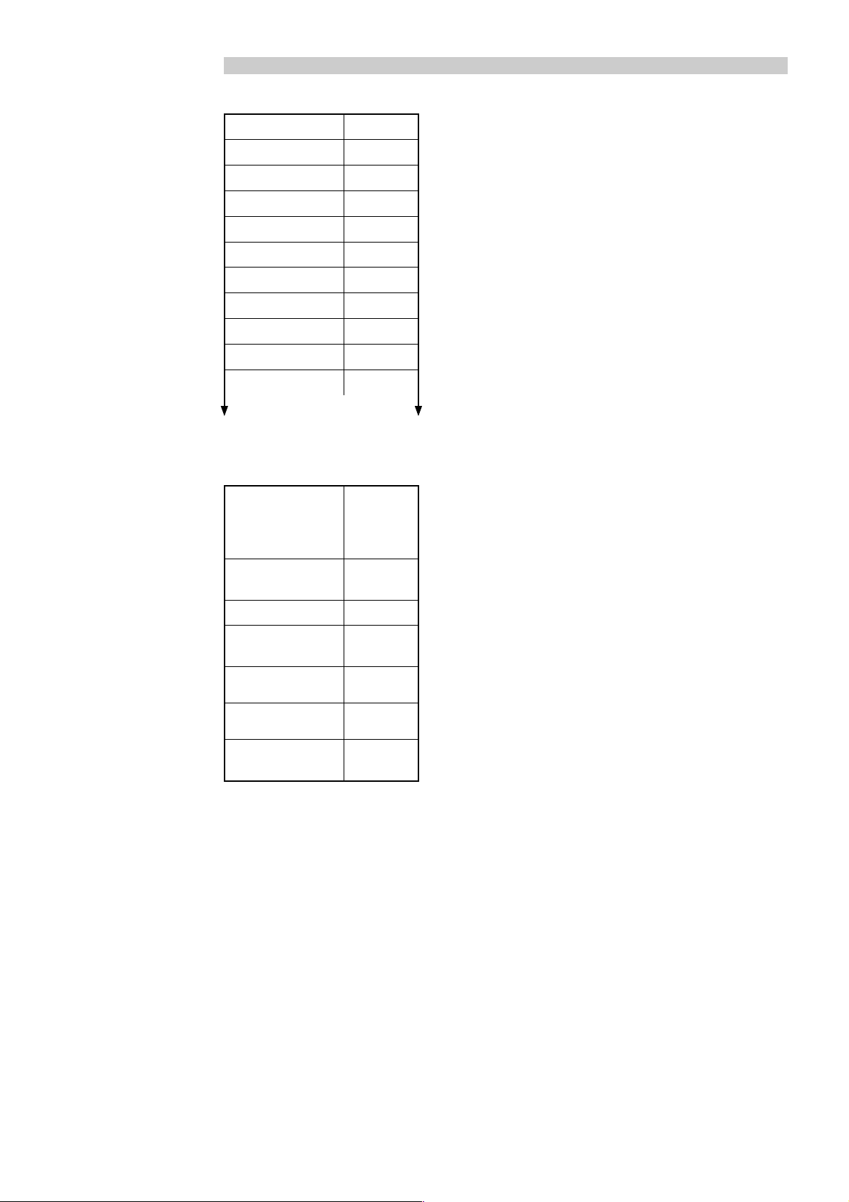
VIF: Value Information Field MULTICAL
®
HEX CODING THEME UNIT SIZE FACTOR
0F 00001111 Energy GJ J x 10
0E 00001110 Energy GJ J x 10
7
6
05 00000101 Energy kWh Wh x 10
06 00000110 Energy kWh Wh x 10
07 00000111 Energy MWh Wh x 10
3
17 00010111 Volume m
16 00010110 Water m
15 00010101 Water m
14 00010100 Water m
13 00010101 Volume m
x 10 m3 x 10 1
3
3
x 10
3
x 10
3
x 10
-1
-2
-3
m3 x 10
m3 x 10
m3 x 10
m3 x 10
2
3
4
0
-1
-2
-3
1000/100/10/1
1
1
1
100/10/1
1
1
1
1
22 00100010 Hour counter Hours Hours 1
3
3E 00111110 Flow m
3D 00111101 Flow m
3C 00111100 Flow m
3B 00111011 Flow l/h m
/h m3/h x 10
3
3
/h x 10
/h x 10
-1
-2
m3/h x 10
m3/h x 10
3
59 01011001 Temp. forward C° C° x 10
5D 01011101 Temp. return C° C° x 10
61 01100001
∆t
2D 00101101 Power kW x 10
2E 00101110 Power MW x 10
2F 00101111 Power MW x 10
K K x 10
-1
-3
-2
W x 10
W x 10
W x 10
/h x 10
-2
-2
-2
2
3
4
0
-1
-2
-3
1
1
1
1
1
1
1
1
1
1/10
6C 01101100 Date G-type Date 1
CODING: Coding of the VIF of the data pack
THEME: Subject of record
UNIT: Wanted unit
SIZE: Unit entered in the VIF
FACTOR: The factor, by which the values of the software
are multiplied, in order to comply with the units
required – see next page.
5511-710 GB/12.2004/Rev. C1
24
Page 25

If multiplied with 10, 100 or 1000 the info field and the prog_NO. field change.
INFO FIELD
7
10
x3x2x1x0 x3x2x1x
10
6
0
5
10
x3x2x1x
4
10
0
x3x2x1x
0
3
10
x3x2x1x
2
10
0
x3x2x1x
0
Reserved for info codes from heat meter
0
= The factor method is used
x
1
x
2
x
x3 = Power x 10
0
x
= Energy x 10
1
x
= Energy x 100, Reading Energy x 100
2
x
= Energy x 1000, Reading Energy x 1000
3
x
The 2 most significant bits in “Energy”
PROGRAM NUMBER
10
x3x2x1x
7
0
10
x3x2x1x
6
0
5
10
x3x2x1x
4
10
0
x3x2x1x
0
3
10
x3x2x1x
2
10
0
x3x2x1x
0
Reserved for the program number from the heat meter
10
x3x2x1x
10
x3x2x1x
1
0
1
0
10
x3x2x1x
10
x3x2x1x
0
0
0
0
The 2 most significant bits in “Reading Energy”
DIF: Data Value Field
EMNE VÆRDI HEX BESKRIVELSE
DATE_AFL 01000010 42H 16 Integer, Historic Value, Type G
Energy_AFL 01001100 4CH 8 Digit BCD, Historic Value, Type A
Water_AFL 01001100 4CH 8 Digit BCD, Historic Value, Type A
RESTEN 00001100 0CH 8 Digit BCD, Current Value, Type A
5511-710 GB/12.2004/Rev. C1
25
Page 26

DATA HEAD
DATA VÆRDI TYPE BESKRIVELSE
1
ID-NO. XXH A Customer number x 10
/customer number x 10
ID-NO. XXH A Customer number x 103/customer number x 10
ID.NO. XXH A Customer number x 105/customer number x 10
ID.NO. XXH A Customer number x 107/customer number x 10
0
2
4
6
MANUFAC. 00101101 C [ascii “K” – 64] x 32 x 32 + 1 [ascii “A” – 64] x 32+
MANUFAC. 00101100 C [ascii “M” – 64] ISO 60870 Standard
GEN. METER 00H C Heat meter generation
MEDIA (HEAT) 04H* el. 0CH** D Code for heat
ACCESS XXH C Counts 1 after each data transfer to the M-Bus Master
STATUS XXH*** D Error code – see below
SIGNATURE 00H C Not in use
SIGNATURE 00H C Not in use
* 04H is used when data is acquired from a return meter
** 0CH is used when data is acquired from a flow meter
*** Error code: 80H ¨ Error during the last collection of heat meter data, data incorrect or too old.
40H ¨ Error in prog_No., e.g. number unknown. I.e. data not correctly encoded.
The error code should be checked when data is received – only apply to “old” M-Bus Slaves.
Heat meter M-Bus Slaves supplied after 15 April 2003 automatically check the STATUS field, and do not
send data on the M-Bus if the field is different from “0”.
The M-Bus Slave makes up to three attempts, at intervals of 5 seconds, to collect correct data from the
meter. If the STATUS field remains different from “0”, automatic data update, or the next user effected
reading will be awaited.
Physical properties
Bus independent of polarity
■
Dynamic impedance = 35 Ω
■
Galvanical isolation from data wires to earth
■
Short-circuit proof
■
Symmetric around earth
■
Transmission speed 300 or 2400 baud
■
Maximum resistance in cable = 29 Ω/180 nF per pair
■
Connection of 230 VAC (M-Bus Master)
■
Current consumption: 10 mA + 1.5 mA per M-Bus Slave.
■
5511-710 GB/12.2004/Rev. C1
26
 Loading...