


Manual
Kamstrup 382
www.kamstrup.com
2
Operating instructions
Connect the meter in accordance with the installation diagram on the meter’s type label.
Depending on the configuration a fixed value will be displayed, or the display will
change between selected indications every 10 seconds.
It is possible to change the display reading manually by activating the push button on
the meter. The available readings will depend on the meter’s configuration.
Security and installation guidelines
The meter shall only to be used for measuring electrical energy and shall operate within
the specified values only.
The meter must be switched off when working on it. It can be highly dangerous to touch
the meter parts when the meter is switched on.
Therefore, the relevant security fuse must be removed and kept in a place where it cannot
be inserted by unauthorized persons.
Current local standards, guidelines, regulations and instruction must be observed. Only
authorized personnel is permitted to install electricity meters.
Meters for direct connection must be protected against short circuit by a security fuse in
accordance with the maximum current stated on the meter.
The meter constant LED blinks proportionally to the consumed active energy.
Only authorized personnel must break the utility sealing.
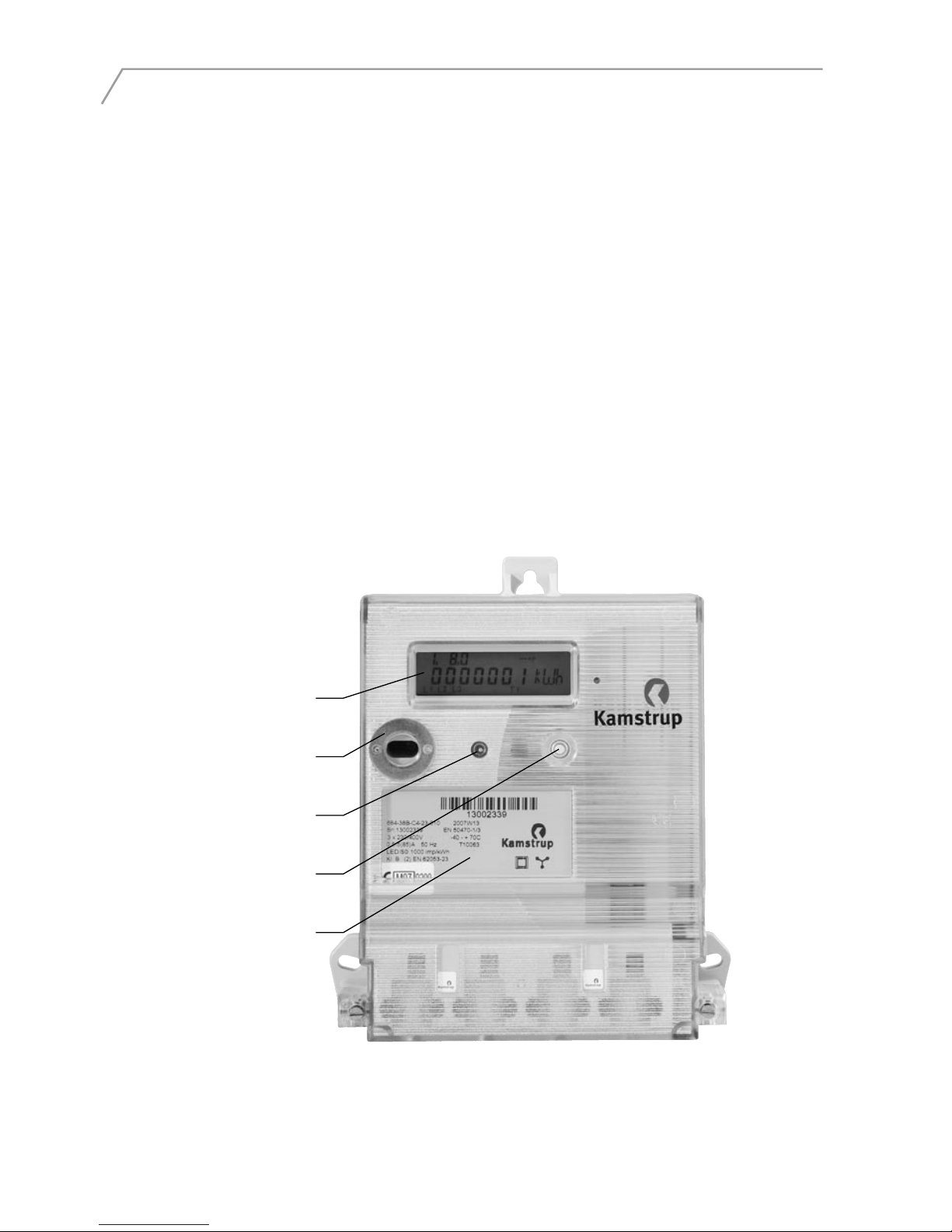
LCD-displayLCD-display
LED (meter constant)LED (meter constant)
Optical interfaceOptical interface
Push buttonPush button
Type labelType label

3
The phase indications L1, L2 and L3 have more than one function, they indicate one of
three situations described below:
Segments L1- L3 Indicate
On Both voltage and load above minimum limit.
Active phases indicate consumption.
Off The voltage is below minimum limit.
Blinking Segments L1 – L3 function as load indicators. Voltage is above and
load is below minimum limit.
The load indicator is active 4 hours after meter reset.
If the load exceeds the minimum limit and the meter is configured with this reading,
consumption will be indicated via the quadrant reading.
The meter’s LED can be used provided that the quadrant indicator is not selected.
The measured unit is displayed in the right side of the display.
Tariff indicating active tariff.
Terminals
Size: 1,5 – 25 mm2
1,5 – 35 mm2
Screw: Pz 2
Torch: 2,5 – 3 Nm
LCD display
L1 L2 L3
T1 T2 T3 T4
7-digit identification field
Quadrant reading Status reading
Unit field
Tariff reading
Phase indication
Value field

4
Installation dimensions
Connection diagrams
The valid connection diagram appears from the type label.
3-phase, 4-wire 3-phase, 3-wire (Aron)
201,6
166,9
684-38A-C4-00-010
Sn:
1
3 x230/400V
50 Hz
LED/S0:1000 imp/kWh
0,5-5(85)A
Kl. A (3) EN 62053-23
EN 50470 1/3
2007W13
40 +70C
T10063
-
- -
201,5
166,9
1 2 3 4 5 6 7 8 9 101112
L1
L2
L3
N
P+
S0
+20-
21
1 2 3 4 5 6 7 8 9 101112
L1
L2
L3
P+
S0
+20-
21
5512-474 GB/04.2007/Rev. A1
 Loading...