

Page 1
KD2446
Non-contact Displacement Measuring
System User’s Manual
This apparatus, when installed and operated per the manufacturer’s recommendations,
conforms with the protection requirements of EC Council Directive 89/336/EEC on the
approximation of the laws of the member states relating to Electromagnetic Compatibility. Refer
to the KD-2440 Declaration of Conformity or contact Kaman Measuring Systems for details.
Description
Displacement Measuring System Model KD-2446 is a non-contact, analog proximity measuring
system. The system operates on a traditional Colpitts oscillator circuit. This low-cost, easy-to-use
system can be utilized for precision static and dynamic measurements of conductive targets.
The KD-2446 system consists of two subassemblies: sensor with integrated cable, and signal
conditioning electronics module. Two standard sensor configurations are available, the 9C and
the 5CM. Selected performance data and dimensions for these two sensors are shown in the
data sheet at www.kamansensors.com. Additional sensor configurations are available upon
request.
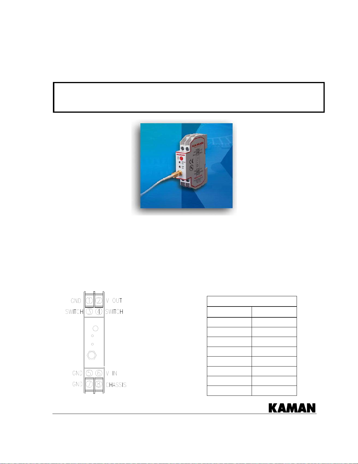
CONNECTIONS CHART
Terminal Signal
1 Gnd
2 V out
3 Switch
4 Switch
5 Gnd
6 V in
7 Gnd
8 Chassis
Copyright © 2006 Kaman Aerospace Corporation
PART NO: 860509-001 Measuring & Memory Systems
Last Revised: 1/11/08 217 Smith Street
Middletown, CT 06457
www.kamansensors.com or 860-632-4442
Page 2
Electronics
The KD-2446 electronics module comes with standard 35mm DIN rail mounting features. The front
panel has two potentiometers for adjusting the GAIN and SWITCH SET POINT levels, and an LED to
indicate switch position.
KD-2446 electronics and sensors utilize SMA type coaxial connectors: female on the electronics,
and male on the sensor cable. The KD-2446 electronics uses screw terminals for voltage input,
analog voltage output, and switch function.
The KD2446 can be adapted to different sensors, target materials, input voltages, and
measurement ranges simply by adjustment of the gain potentiometer. It contains a ten-volt
internal regulator to provide a clean repeatable analog voltage output signal. Input voltage must
be a regulated +12 to +24 VDC supply. Note that variations in input voltage will affect the output.
Adjustment and Calibration
The gain (ratio of output voltage to target displacement) is used to adjust the output slope (output
per displacement). Turning the potentiometer clockwise increases the gain. When ch anging
types of target materials or power supply voltages, it will be necessary to readjust the gain for the
desired output voltage. The KD-2446 can easily be adjusted or “calibrated” to obtain maximum
output per displacement, maximum range, or any variation in between.
Minimum gain is defined as the lowest gain setting obtainable without pulling the circuit into
saturation. Minimum gain can be obtained by setting the sensor displacement to a point within the
usable range (preferably mid range), then slowly decrease the gain potentiometer until the output
saturates. At this point, increase the gain slightly to a point just above saturation (the output
begins to change with a gain increase).
A typical calibration is performed as follows:
1. Physically adjust the sensor to its minimum distance to the target. This is its offset distance and
is the distance at which the output begins to respond, or the point at which minimum desired
output is obtained.
2. Move the target to its maximum distance from the sensor, based on desired sensor range.
3. Increase the gain potentiometer until maximum desired output is obtained.
4. Move the target back to minimum distance and check output. Repeat steps 1-3 as necessary.
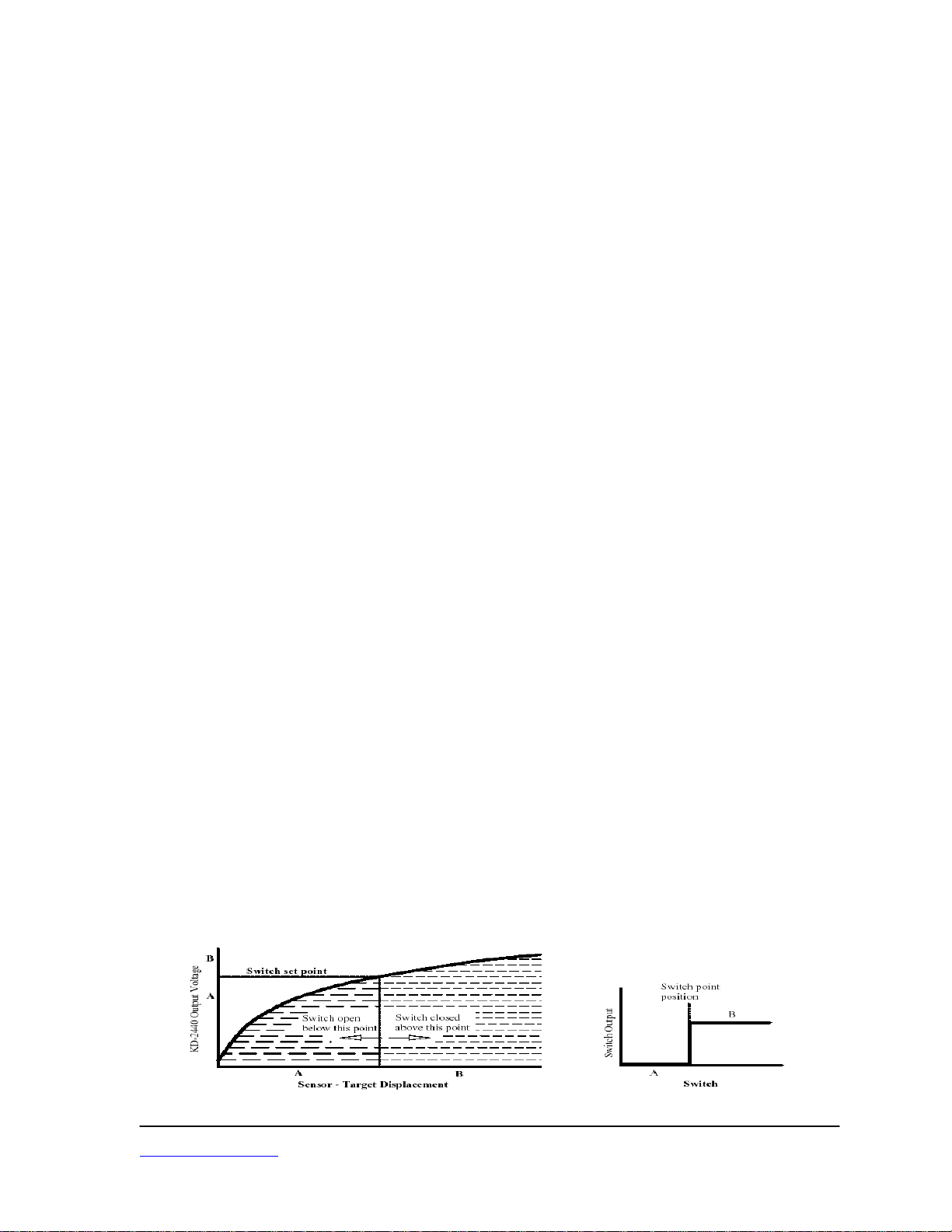
Switched Output Operation
The KD-2446’s switched output is a simple on / off switch with a corresponding LED indicator lamp.
The switch is in an open condition when the sensor to target distance is below the set point. The
switch can be adjusted to trip anywhere along the sensor range using the “Switch Adj” potentiometer
on the front panel. The front panel LED illuminates to indicate a closed switch position. Typical
Switching speed is as follows: Turn on – 0.25mS, Turn off – 0.05mS.
Kaman Aerospace Corporation PART NO: 850609-001
www.kamansensors.com
Last Revised: 1/11/08
2
 Loading...