

Page 1

GMS-750RS Gap Measuring System
User’s Manual
Copyright © 2013 Kaman Precision Products
PART NO: 860527-001 A Division of Kaman Aerospace Corporation
Last Revised: 8/23/2013 217 Smith Street
Middletown, CT 06457
www.kamansensors.com
Page 2
Product Description
The GMS-750RS is a measuring instrument designed specifically to measure the rotor-stator gap in large
power generators. It is based on Kaman’s proven eddy current technology used for
position/displacement sensing.
Included with the GMS-750RS are: Wall Transformer 15Vdc Power Supply, and Insertion Depth Stops.
The digital display reads the measured gap in inches over the calibrated span of 0.250” to 0.750”, with
0.001” resolution.
Normal Operation
The unit as shipped is calibrated over the 0.250” to 0.750” range and is ready to use. Insertion stops are
provided for repeatable depth of insertion when making rotor-stator gap measurements. Install them in
the desired holes provided.
Gripping the handle of the device in one hand and steadying with the other, push the spring end of the
GMS-750RS into the gap between the rotor and stator. The springs act as the target for the eddy current
sensor mounted between them. As the springs deflect upon insertion the eddy current sensor will
measure the distance between the springs and display the distance in inches between the outside
surfaces of the springs on the digital display.
Calibration
The unit is supplied with factory calibration. As with most measurement devices recalibration is
recommended at periodic intervals. Kaman recommends an annual recalibration which can be performed
by following the calibration procedure that follows, or the unit can be returned to Kaman for factory
recalibration, contact Kaman at 800-552-6267 or measuring@kaman.com
NOTE: Any means to accurately depress the target springs to the 0.250”, 0.375” an 0.750” gaps can be
used to perform a calibration.
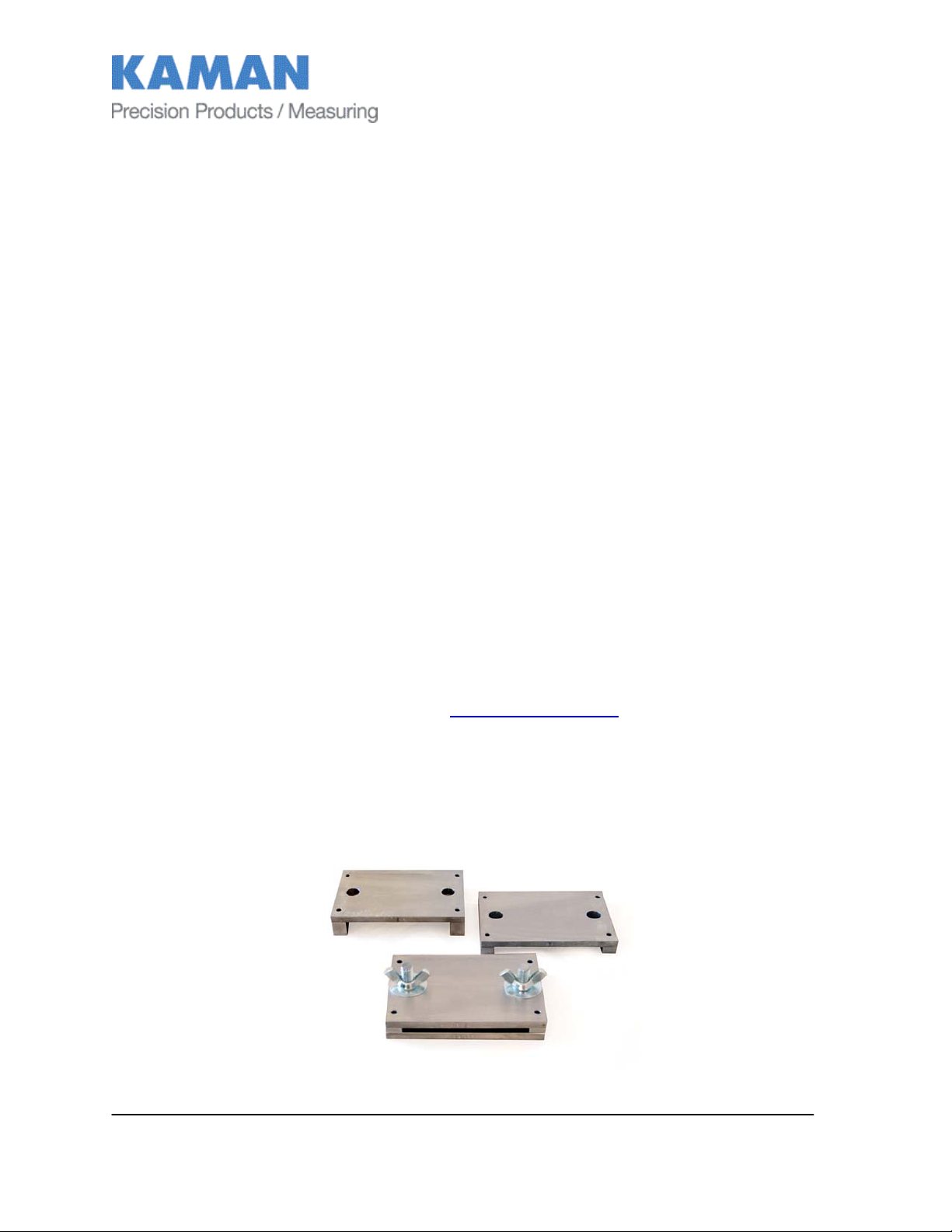
An optional Calibration Fixture is available for calibrating the GMS-750RS consisting of: a Base Plate with
2 threaded guide pins with washers and wing nuts, and 3 Calibration Plates; .250”, .375” and .750”. Each
Calibration Plate is stamped with the dimensional value on the front of the spacer legs.
.
www.kamansensors.com PART NO: 860527-001
Last Revised 8/23/2013
- 2 -
Page 3

The calibration of the GMS-750RS is a 3 point calibration. The electronics will be taught the spring
deflection using the 3 Calibration Plates.
To calibrate, remove Insertion Depth Stops.
Place the Base Plate with the two threaded guide pins on a workbench or other suitable level surface with
guide pins facing up. Set the GMS-750RS on the Base Plate between the guide pins. The center (length
and width) of the lower spring should be aligned the two guide pins.
Place the .250” Calibration Plate over the upper spring with guide pins aligned in the holes. Install a
washer and wing nut on each guide pin.
While pushing down on the .250” Calibration Plate, tighten the wing nuts until the Calibration plate is
firmly seated on the Base Plate. Check to make sure both of the legs on the Calibration Plate are in full
contact with the Base Plate.
Depress and hold the calibration pushbutton located on the side of the display enclosure with the point of
a pen or end of a paper clip for a minimum of 6 sec, the calibration LED will begin to slowly flash green.
While pushing down on the .250” Calibration Plate, loosen and remove the wing nuts allowing the
Calibration plate to release the spring compression. Remove the .250” Calibration Plate.
Place the .375” Calibration Plate over the upper spring with guide pins aligned in the holes. Install a
washer and wing nut on each guide pin.
www.kamansensors.com PART NO: 860527-001
Last Revised 8/23/2013
- 3 -
Page 4

While pushing down on the .375” Calibration Plate, tighten the wing nuts until the Calibration plate is
firmly seated on the Base Plate. Check to make sure both of the legs on the Calibration Plate are in full
contact with the Base Plate.
Momentarily depress and release the calibration pushbutton with the point of a pen or end of a paper clip.
The calibration LED will begin to rapidly flash green.
While pushing down on the .375” Calibration Plate, loosen and remove the wing nuts allowing the
Calibration plate to release the spring compression. Remove the .375” Calibration Plate.
Place the .750” Calibration Plate over the upper spring with guide pins aligned in the holes. Install a
washer and wing nut on each guide pin.
While pushing down on the .750” Calibration Plate, tighten the wing nuts until the Calibration plate is
firmly seated on the Base Plate. Check to make sure both of the legs on the Calibration Plate are in full
contact with the Base Plate.
Momentarily depress and release the calibration pushbutton with the point of a pen or end of a paper clip.
The calibration LED stops flashing and returns solid green.
While pushing down on the .750” Calibration Plate, loosen and remove the wing nuts allowing the
Calibration plate to release the spring compression. Remove the .750” Calibration Plate.
Both the Calibration LED and the Power LED should be solid Green indicating a good calibration.
If the Power LED is Red, this indicates a bad calibration. Repeat the calibration process above.
Install the Insertion Depth Stops in the desired position.
Calibration is retained within the unit when powered down. The frequency of recalibration is left up to the
user.
Tare
NOTE: Any means to accurately depress the target springs to the 0.375” gap can be used to tare the unit.
Taring the GMS-750RS will shift the output to accommodate minor variations from the original calibration
that can be caused by environmental temperature changes.
To tare the unit, set up the Calibration Base Plate as described in ‘Calibration’ above. The 0.375”
Calibration Plate, is used to tare the unit.
www.kamansensors.com PART NO: 860527-001
Last Revised 8/23/2013
- 4 -
Page 5

While pushing down on the .375” Calibration Plate, tighten the wing nuts until the Calibration plate is
firmly seated on the Base Plate. Check to make sure both of the legs on the Calibration Plate are in full
contact with the Base Plate.
Momentarily depress the calibration push button. The unit will tare to .375” NOTE: THE TARE
FUNCTION CAN ONLY BE USED AT THE .375” GAP.
General Care and Maintenance
If the unit becomes soiled use a normal spray type household cleaner and wipe it down with a clean cloth.
A light lubricating oil should be applied to the stainless body where the target springs ride.
A light lubricating oil can be applied to the outside of the target springs if desired.
System Specifications For Assistance
Kaman Precision Products
Input power: 110VAC 3730 Sinton Road #100
Calibrated range: 0.250” – 0.750” Colorado Springs, CO 90807
Resolution 0.001” 1-800-562-6267
1-719-635-6957
measuring@kaman.com
www.kamansensors.com
www.kamansensors.com PART NO: 860527-001
Last Revised 8/23/2013
- 5 -
 Loading...