

Page 1

Reference Manual
SERIES 8000
ENCLOSURES
Copyright © 2000 Kaman Aerospace Corporation
PART NO: 860093-001 Measuring & Memory Systems
Last Revised: 3/16/01 217 Smith Street
Middletown, CT 06457
www.kamansensors.com or 860-632-4442
Page 2

Page 3

Series 8000 Enclosures
Reference Manual
1/2 Rack Instrumentation Case (3U/42HP)
3/4 Rack Instrumentation Case (3U/63HP)
Full 19" Subrack (3U/84HP)
Kaman Measuring Systems
P/N 860093-001, Revised 3/16/01
Page 4

4
Series 8000 Systems
The Series 8000 is a modular packaging system for Kaman Instrumentations line of inductive
displacement transducer electronics. The Series 8000 enclosures integrate various measuring
channels, function cards, power supplies, and displays into a coherent application specific
industrial package. Sensors for the measuring channels are available that measure
displacements in the microinch/nanometer ranges as well as sensors that can make accurate
displacement measurements at up to 1000oF. Function cards are available that can take the
displacement measurement and process the signal to measure ID, OD,runout, or out of
tolerance conditions. The versatility and flexibility of the 8000 system is virtually endless.
This manual is designed to help put it all together for the specific system you have purchased.
features: Eurocard/Eurorack format
Up to 12 channel systems
Integral rear mounted power supplies
Terminal block I/O
Optional 1/8 DIN display modules
Multi-channel Scalable displays
Inductive sensing technology
Plug-in function modules for:
Dynamic signal measurement
Set point window comparators
Summation for thickness/ID/OD measurement
4-20 mA outputs
Page 5

5
Table of Contents Page
Getting Started Quickly 7
Series 8000 Enclosures 8
Subracks 8
Instrument Enclosure 13
NEMA 17
Integral Power Supply 18
Input Voltage Selection (120VAC/240VAC) 19
The Internal Back Plane 23
Internal Back Plane Connectors 25
Adding Additional Modules 26
The Back Panel 29
Back Panel Power Input 29
Back Panel I/O and Labeling 30
Back Panel Sensor Inputs 31
The Front Panels 32
Module Side Panel Labeling 32
MCD-8000 and 1/8 DIN Panel Mounted Displays 33
Using the Multi-Inputs 35
Input wiring to the Display 36
0-10VDC Display Input Configuration 37
+/-5VDC Display Input Configuration 37
+/-10VDC Display Input Configuration 37
4-20mA Display Input Configuration 38
Calibration 39
Appendix A -- Measuring Channel Configuration 43
Basic Measuring Channel Configuration 44
Appendix B -- Function Card Configuration 45
VC8000 Voltage to Current Converter Configuration 46
SC8000 Summation/Comparator Configuration 47
DY8000 Dynamic Module Configuration 48
SP8000 Dual Set Point Configuration 49
Appendix C -- MCD-8000 Display Specifications 50
MCD 8000 Functional Specifications 50
MCD 8000 Performance Specifications 51
MCD 8000 Environmental/Physical Specifications 51
Appendix D -- Replacement or Expansion Parts 52
Appendix E – Warranty, Customer Service and Service/Repair 54
Page 6

6
List of Illustrations Page
fig. 1 -- Full 19" Subrack Rear/Front Outline drawing 9
fig. 2 -- Full 19" Subrack Top View Outline Drawing 10
fig. 3 -- Full 19" Subrack Rear/Front with Display 11
fig. 4 -- Full 19" Subrack Rear/Front with Dual Display 12
fig. 5 -- 1/2 Rack with Display Outline Drawing 14
fig. 6 -- 1/2 Rack Outline Drawing 15
fig. 7 -- 3/4 Rack with Display Outline Drawing 16
Table 1 -- Power Supply Specifications 18
fig. 8 -- Power Entry Module 19
fig. 9 -- Accessing the Voltage Selector Card 19
fig. 10 -- Voltage Selector Card Orientation 20
fig. 11 -- Top View of Main board on display. 22
fig. 12 -- Physical Eurocard Pin Locations 23
Table 2 -- Electrical Standards for Pinout 24
fig. 13 -- Single Coil Coaxial 25
fig. 14 -- Dual Coil Coaxial 25
fig. 15 -- Back Plane Template 28
fig. 16 -- Power Entry Module 29
Table 3 -- Terminal Block Labeling 30
fig. 17 -- Back Panel Sensor Inputs 31
fig. 18 -- Typical Module Side Panel Labeling 32
fig. 19 -- Single 1/8 DIN Mounting Panel 814873-001 33
fig. 20 -- Dual 1/8 DIN Mounting Panel 814873-002 34
fig. 21 -- MCD 8000 Front Panel 35
Table 4 -- Displayed Outputs 35
fig. 22 -- MCD 8000 Input Wiring 36
fig. 23 -- MCD 8000 Power Wiring 36
fig. 24 -- Voltage/Current Input Dip Switch 38
fig. 25 -- Diodes For Loop Continuity in Current Mode 38
fig. 26 -- MCD 8000 Adjustment Switches 40
fig. 27 -- Process/Scaling Dip Switch 40
fig. 28 -- Button Function Legend 42
Table 5 -- MCD-8000 Error Message Table 42
Table 6 -- Series 8000 Sensor Family 43
fig. 29 -- Basic Measuring Channel 44
fig. 30 -- Module Reference Dimensions 45
fig. 31 -- VC8000 Voltage to Current Converter 46
fig. 32 -- SC8000 Summation/Comparator 47
fig. 33 -- DY8000 Dynamic Module 48
fig. 34 -- SP8000 Dual Set Point 49
Page 7

7
Getting Started Quickly
The Series 8000 rack systems are typically prewired and set up at the factory with all
measuring channels and function cards installed. To get started with the 8000 system you will
need to:
a Install the sensors in the application or cal fixture
b Connect the sensors to the enclosure (see page 30)
c Connect the power cord and turn on the unit
d If you have a display see page 32
e If you have no display see page 29 on back panel I/O
As with any complex electronics system you should thoroughly familiarize yourself with all
manuals dealing with the product. Included with the system are the appropriate manuals for
any measuring channels and function cards purchased. Please refer to these manuals for
specific information.
Warning: The integral power supply in racks utilize high voltage
(120 or 240VAC). Unplug the unit before servicing.
Page 8

8
Series 8000 Enclosures
Subracks
The subrack is a 19" wide frame having solid side panels and horizontal rails across the top
and bottom to hold the system modules in place. Use of a subrack enables you to install your
Series 8000 system into a standard 19" test equipment rack, or bolt it into a NEMA enclosure.
The subrack has a built in 120VAC/240VAC selectable power supply to provide +/-15VDC at 1
amp. The subrack also can be configured with either one or two MCD 8000 display modules
that have up to six selectable inputs. The display modules draw no current from the +/-15 volt
supply.
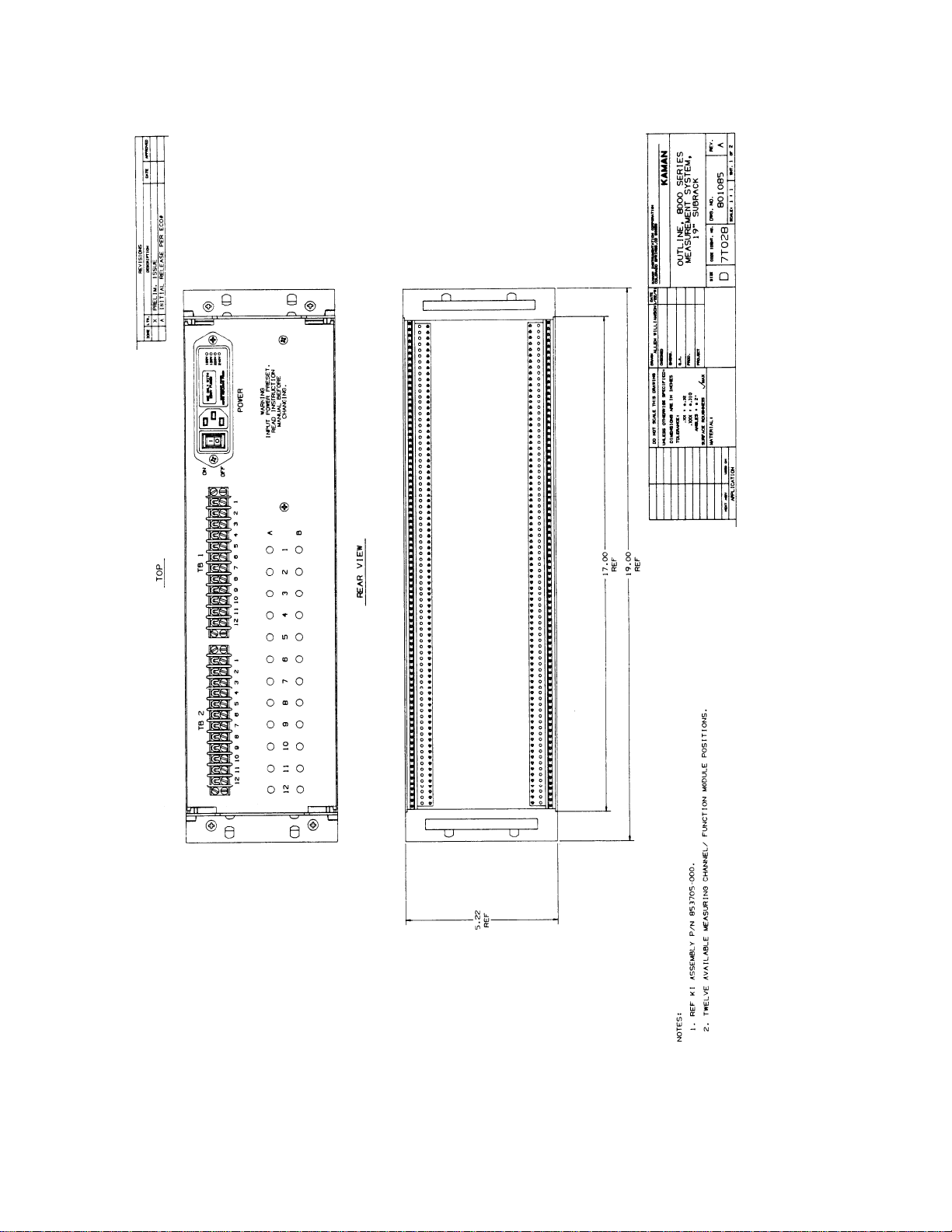
Full 19" Sub-Racks - 3U/84HP Instrumentation Subrack
Part Number Configuration
853705-000 No display meter, 12 available positions
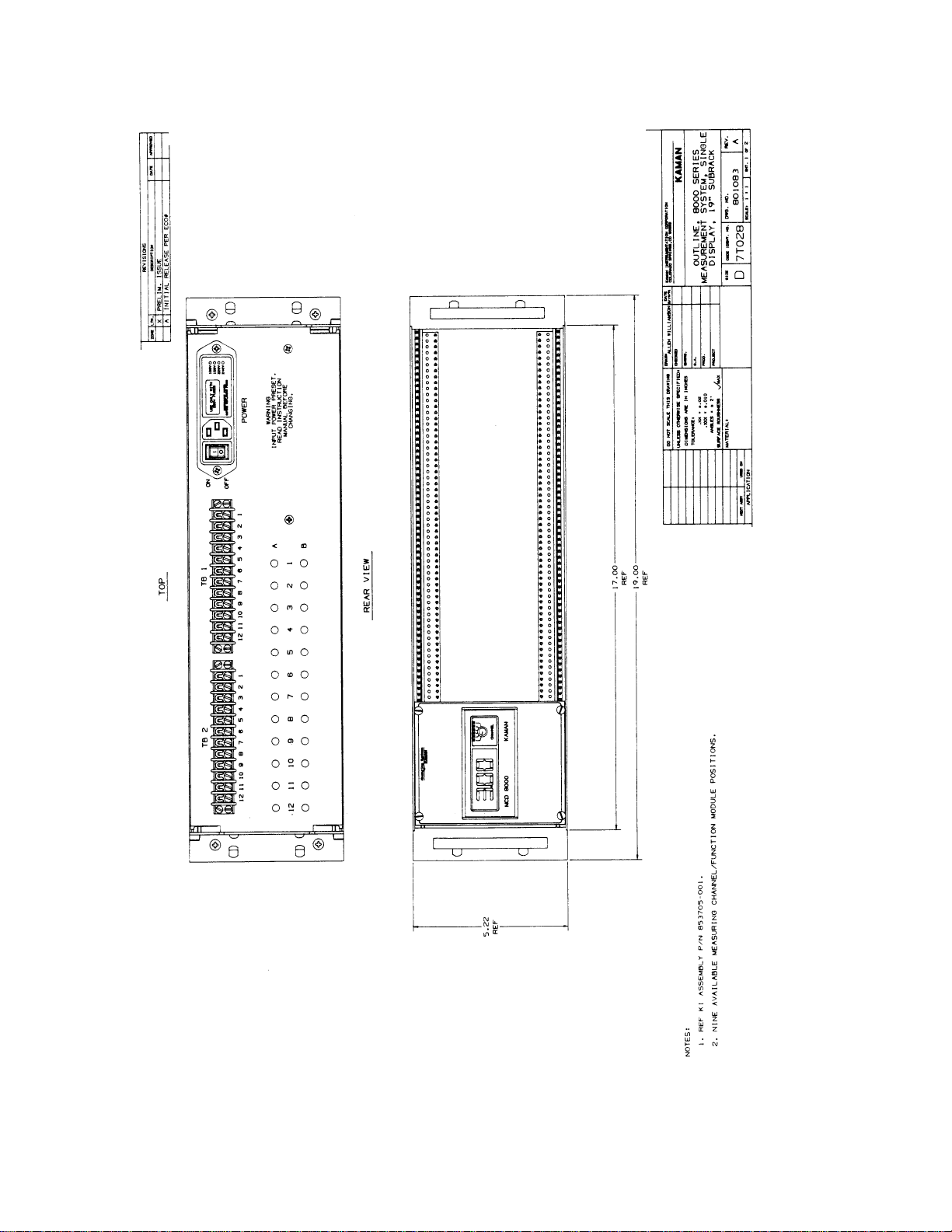
853705-001 One display meter, 9 available positions
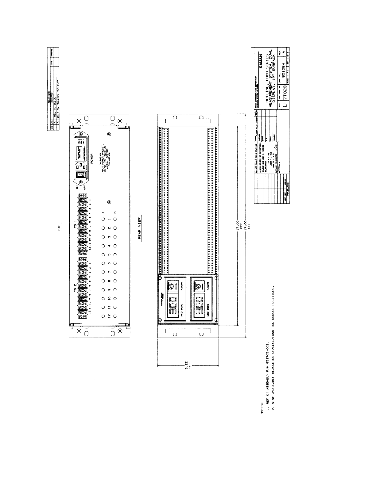
853705-002 Two display meters, 9 available positions
Page 9
9
fig.1 – Full 19” Subrack Rear/Front Outline Drawing
Page 10
10
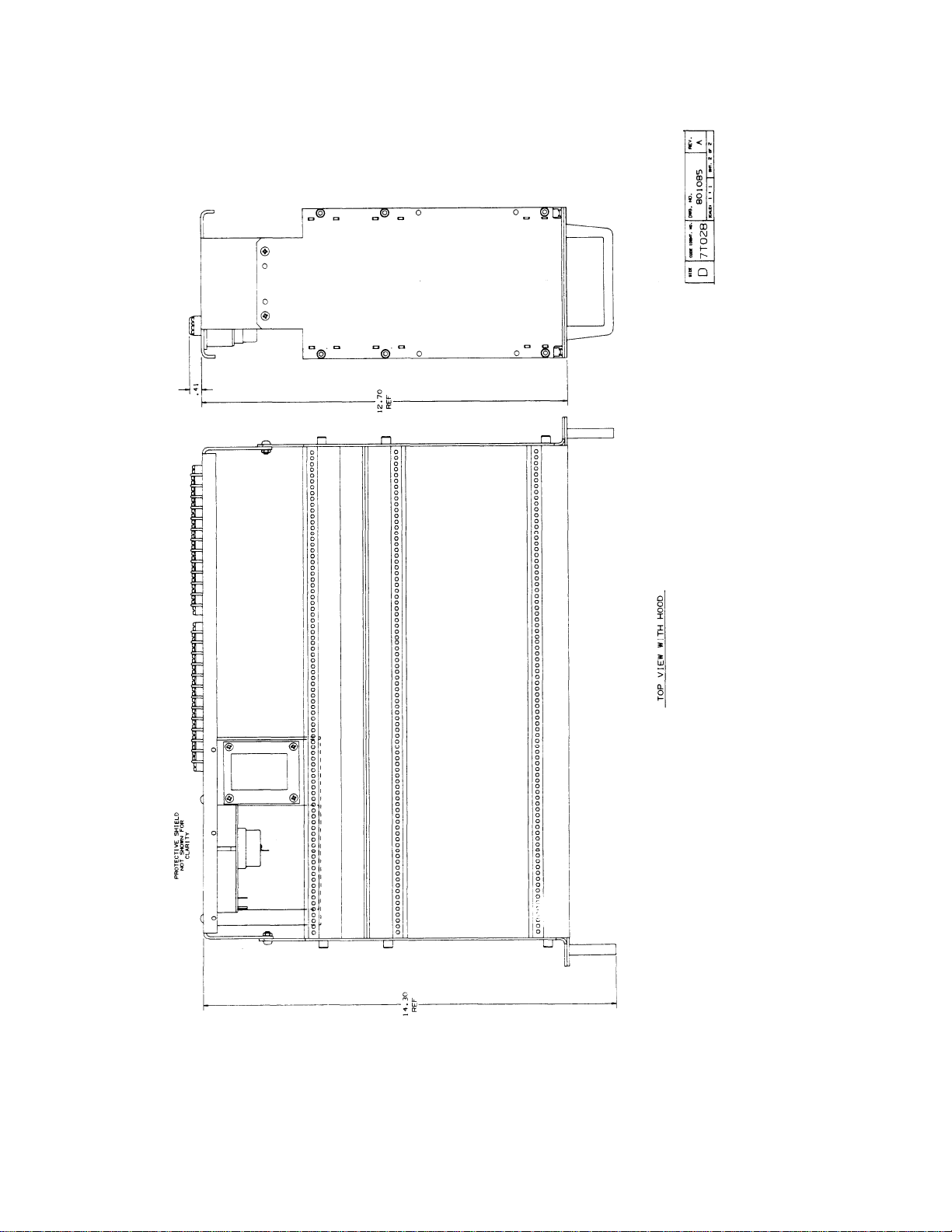
Fig. 2 – Full 19” Subrack Top View Outline Drawing
Page 11
11
fig. 3 – Full 19” Subrack Rear/Front with Display
Page 12
12
fig. 4 – Full 19” Subrack Rear/Front with Dual Display
Page 13

13
Instrument Enclosure
The instrument case is a fully enclosed stand-alone enclosure for your series 8000 system with
a tilt bar to elevate the front of the case. The subrack has a built in 120VAC/240VAC
selectable power supply to provide +/-15VDC at 500 milliamp. The subrack also can be
configured with either one or two MCD 8000 display modules that have up to six
selectable inputs. The display modules draw no current from the +/-15DC volt supply.
1/2 rack enclosures - 3U/42HP Instrumentation enclosure
Part Number Configuration
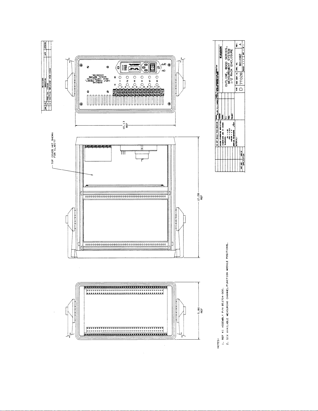
853704-000 No display meter, 6 available positions
853704-001 One display meter, 3 available positions
3/4 rack enclosures - 3U/63HP Instrumentation enclosure
Part Number Configuration
853723-001 One display meter, 6 available positions
Page 14
14
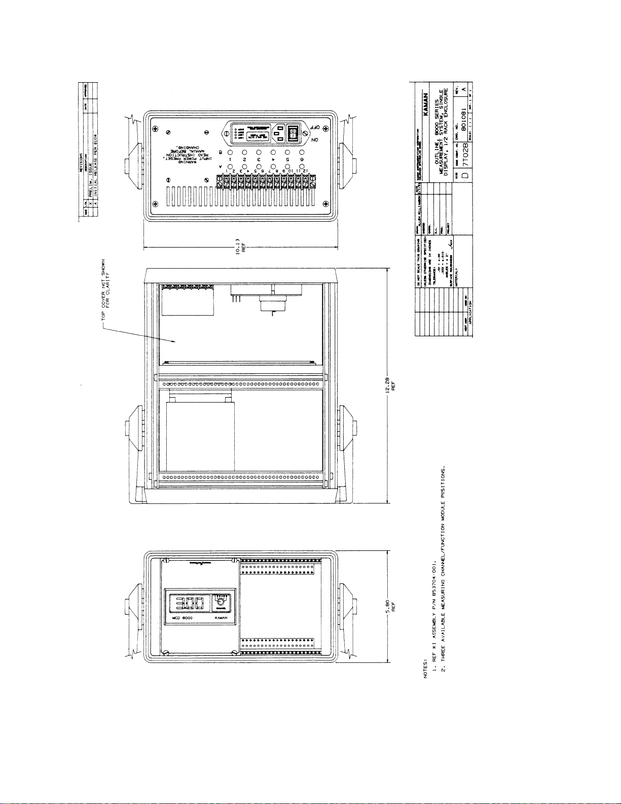
fig.5 – ½ Rack with Display Outline Drawing
Page 15
15
fig. 6 – ½ Rack Outline Drawing
Page 16

16
fig. 7 – ¾ Rack with Display Outline Drawing
Page 17

17
NEMA
The NEMA 12 configuration is an 8"x8"x4" continuous hinge enclosure. It can contain either 1
or 2 synchronized measuring channels and an optional function card. An optional integral
power supply and/or display is available. In the NEMA the modules do not have separate
enclosures. This configuration is not described further in this manual, please refer to the NEMA
manual PN 860060 for further information on the NEMA enclosure.
PN Configuration
853638-001 Standard NEMA
853639-001 NEMA with internal 120VAC power supply
853640-001 NEMA with display
853641-001 NEMA with 120VAC PS and display
853639-001E NEMA with 240 VAC power supply
853641-001E NEMA with 240 VAC power supply and display
Page 18

18
Integral Power Supply
Warning: The integral power supply in racks utilize high voltage
(120 or 240VAC). Unplug the unit before servicing.
The power supply for the series 8000 rack enclosures are integral to the chassis and mounted
on the back panel for better heat dissipation. All of the Series 8000 power supplies provide a
+/-15VDC+/-.5V linear regulated output for low noise operation. The available current is
500mA per side in the 1/2 and 3/4 rack configurations and 1A per side in full rack
configurations. Most measuring channels and function cards from Kaman typically draw less
than 70mA per side. When adding additional function cards or measuring channels to the unit
you should check on the actual current amount by referring to the specifications on each module
and adding up the total current draw from the power supply. For example, if you had 10
measuring channels you should allow for the supply to be able to handle 700mA (full rack
configuration). The MCD-8000 or other 1/8 DIN display modules are powered directly off the
AC input and therefore draw no current from the integral supplies. The power supply
specifications are summarized in table 1 below:
Full 19" Sub-Racks - 3U/84HP Instrumentation Subrack
Input Power: 115VAC +/-10%, 50-60 Hz, .5A fuse
230 VAC +/-10%, 50-60Hz, .25A fuse
Output Voltage: +/-15VDC +/-.5V
Output Current: 1A per side
3/4 rack enclosures - 3U/63HP Instrumentation enclosure
Input Power: 115VAC +/-10%, 50-60 Hz, .5A fuse
230 VAC +/-10%, 50-60Hz, .25A fuse
Output Voltage: +/-15VDC +/-.5V
Output Current: .5A per side
1/2 rack enclosures - 3U/42HP Instrumentation enclosure
Input Power: 115VAC +/-10%, 50-60 Hz, .5A fuse
230 VAC +/-10%, 50-60Hz, .25A fuse
Output Voltage: +/-15VDC +/-.5V
Output Current: .5A per side
Table 1 -- Power Supply Specifications;
Page 19

19
Input Voltage Selection (120VAC/240VAC)
Warning: When you change the input voltage on the rear panel
you must also change the MCD 8000 input voltage
or you may damage the unit.
Warning: The integral power supply in racks utilize high voltage
(120 or 240VAC). Unplug the unit before servicing.
To change the input voltage you must first select the proper input voltage on the power entry
module on the unit. To change the selected voltage:
a Open the cover using a small blade screwdriver or similar tool. Set aside
the cover/fuse block assembly and pull the voltage selector card straight
out of the housing. See fig. 9 on accessing the voltage selector card.
fig. 8 -- Power Entry Module;
fig. 9 -- Accessing the Voltage Selector Card;
Page 20

20
b Using the indicator pin orient the selector card so that the desired
voltage is readable at the bottom. Orient the indicator pin to point up
when the desired voltage is readable at bottom ( note that when indicator
pin is fixed, successive voltages are selected by rotating the card 90o
clockwise). See fig. 10 for voltage selector orientation.
c Insert voltage selector card into housing with printed side of card facing
toward IEC connector and edge containing the desired voltage first.
Replace cover and verify that indicator pin shows the desired voltage.
fig. 10 -- Voltage Selector Card Orientation;
Page 21

21
If you have an MCD 8000 (for other 1/8 DIN panel meter configurations you will need to see
the specific manual on the meter for changing the input voltage) 110VAC or 220VAC is
selectable using a switch on the indicators main circuit board. Check the instruments tag for
the voltage range set at the factory. If you are changing the input voltage to the unit you will
need to set this switch appropriately. To change the input voltage on the MCD 8000 display
module perform the following steps:
Warning: When you change the input voltage on the rear panel
you must also change the MCD 8000 input voltage
or you may damage the unit.
Warning: The integral power supply in racks utilize high voltage
(120 or 240VAC). Unplug the unit before servicing.
a Remove the MCD-8000 unscrew the 4 screws holding the unit in the
chassis. You will need to very carefully pull this out of the enclosure to
get at the voltage selector switch. Be careful not to pull out any of the
wires attached to the terminal block of the MCD 8000.
b Remove the input selector knob and face plate and spread the black box
to remove the PC board. There is a plastic tab on the bottom side that
holds the PC board in place. Spreading the box slightly will allow the PC
board to slip over the top.
c On the main display board set the voltage switch for the appropriate
input voltage and replace the unit. See fig. 11 for a top view of the main
display board.
d Reinstall the display module in the unit.
Page 22

22
fig. 11 -- Top View of Main board on display.;
Warning: Dangerous voltages are exposed at the screw terminals.
Always remove power before working in this area
for rewiring, disassembly, and all other activities
that involve proximity to electrical circuitry.
Page 23

23
The Internal Back Plane
The back plane of the series 8000 rack system is typically hand wired at the factory. Channels
configured as blanks are normally left unconfigured because it is not always specified as to
what will be in a slot in the future. In designing the series 8000 modules some standards have
been adhered to accommodate expansion. The diagram in figure 12 details physical pin
locations for the standard Eurocard connector. Table 2 gives the electrical standards used for
designing compatible modules. Figure 15 is a template used for special wiring to the back
plane. See the section on Adding Additional Modules for information concerning expansion.
When connecting other 3rd party equipment to the Series 8000 you must take care to avoid
drawing to much power from the supply and/or adding additional noise to the output from the
system (especially with digital cards such as A/D, D/A, or CPU).
fig. 12 -- Physical Eurocard Pin Locations;
Page 24

24
Caution: Be careful when connecting power, incorrect connections may damage your system.
function Pin C Pin A function
+15VDCin 2 2 +15VDCin
SPL 4 4 SPL
-15VDCin 6 6 -15VDCin
SPL 8 8 SPL
Gnd 10 10 Gnd
I/O 12 12 I/O
I/O 14 14 I/O
I/O 16 16 I/O
I/O 18 18 I/O
I/O 20 20 I/O
I/O 22 22 I/O
Aux 24 24 Aux
Gnd 26 26 Gnd
I/O 28 28 I/O
Gnd 30 30 Gnd
I/O 32 32 I/O
Table 2 -- Electrical Standards for Pinout;
Pins labeled I/O are either input/output, pins labeled Gnd are always ground, pins labeled Aux
are generally reset type functions, pins labeled SPL are not normally used but may be
depending on the density required for pinout, the power supply input pins are obvious and the
function cards are always set up to allow a +/-15 volt input.
Page 25

25
Internal Back Plane Connectors
The bare chassis eurocard connector is available for expansion and is part number 826020002 for function cards. For most Kaman measuring systems use the SMA connector for coaxial
connection, two part numbers are available: 853503-001 for single coil systems or 853503002 for dual coil or differential systems. These connectors are prewired to the eurocard
connector with bulkhead SMA's.
fig. 13 -- Single Coil Coaxial; fig. 14 -- Dual Coil Coaxial;
Page 26

26
Adding Additional Modules
To add additional modules you will need to wire in additional Eurocard connectors to the back
panel. You must have a soldering iron and 24AWG bus wire as well as insulated wire to
connect any outputs that are required to the display or the back panel.
Warning: The integral power supply in racks utilize high voltage
(120 or 240VAC). Unplug the unit before servicing.
1) Using the back plane template provided in fig. 15 map out the wiring of the unit.
Power and ground connections from the power supply are shown in the diagram.
Measuring channel and function cards I/O is shown in tables at the top of the
template. You should refer to the specific manual on the module you are adding
for further pinout information. The measuring channel sensor SMA pigtail
connectors will already attached to the Eurocard connector.
2) Determine the connector required:
If you are adding a measuring channel:
you will need to have the 853503-001 or 853503-002 (depending on whether the
measuring channel has one or two coils) connector with the coaxial bulkhead
SMA connector (which comes with a measuring channel).
If you are adding a function card:
you will need to have the 826020-002 Eurocard connector which comes with a
function card.
3) Insure that the power cord is removed from the unit
4) Remove the back panel
On subracks:
you should only remove two screws and carefully flip the panel up to avoid
breaking any wires already connected.
On instrumentation cases:
you should remove the top panel and the back panel being careful not to put
any excess strain on connections already made.
5) Install the connector spaced the same number of holes as the rest of the
connectors in the unit (there should be 6 empty holes between connectors). The
2 M2.5x6 screws (supplied -- Kaman PN 826028-146) should be used to secure
the connector firmly in place. If you are installing a measuring channel and
have and SMA pigtail it is best to wait until later to secure the SMA to the back
panel.
Page 27

27
6) Install the guide rails. Be sure to space as other guide rails in the unit are
spaced (there should be 5 empty holes between guide rails). The guide rails
snap into place in the upper and lower horizontal parts of the rack.
7) Solder in the power and ground connections. You will need to use 24AWG bus
wire to connect the power and ground of any Kaman supplied module. The back
plane template (fig. 15) shows the power and ground connections.
8) Solder in connections with insulated bus wire to the display and/or back panel
as required for the application. The wiring template in fig. 15 gives the basic
pinout for measuring channels and function cards. For third party modules
you will have to refer to the specific information provided by the manufacturer.
Typical connections are from the measuring channel out+ (C14/A14) and out-
(A16/C16) to the display module (see the section on Input Wiring to the
Display) or to an available pin on the back panel terminal block. If you are
wiring in a function card you will need to use the measuring channel outputs as
inputs to the function card. Typical function cards have inputs located on
A12/C12 for channel 1 input and A16/C16 for channel 2 input. The location of
the outputs vary depending on the type of output required.
9) Once you have carefully checked the wiring of outputs and inputs connect the
SMA to the back panel and carefully reassemble the unit.
Page 28

28
fig. 15 – Back Plane Template
Page 29

29
The Back Panel
The exact back panel configuration will depend on the specific enclosure, measuring channels,
and function cards to build a system. Figures 3, 5, and 7 show the back panel configurations
for the 3 standard rack mounted enclosure types. Exact terminal block outputs depend on the
measuring channel/function module configuration of the specific rack. See the section on
Back Panel I/O and Labeling for specific information on terminal block outputs.
Back Panel Power Input
The back panel has a universal IEC AC power input jack with on/off switch. The units can be
configured for either 120VAC or 240VAC use (Note: If you switch power input to the unit and
you have a display you must
AC input -- failure to do so will damage the unit). See the section on Input Voltage Selection
for switching the AC input. The power switch for the unit is located on the power entry
module.
also switch the display power input as it is powered directly off the
fig. 16 -- Power Entry Module
Page 30

30
Back Panel I/O and Labeling
Each back panel has terminal blocks used for I/O with special laser markings depending on
the cards installed in the rack. The half rack has one 12 position terminal block, the 3/4 and
full racks have two 12 position terminal blocks. The outputs are labeled to be consistent with
the table below where `x' refers to the channel number. Unfortunately, because of the density
of the outputs on the back plane vs. the available outputs on the terminal blocks all outputs
will not always be available on the terminal block. If you need a specific output not provided
on the back panel terminal block please call the factory for information. If you have a function
card not listed here please refer to the manual for the specific function card on terminal block
labeling information.
TB
Module label Function
8200 CHx Signal out of measuring channel
GND Ground from measuring channel
8200HT CHx Signal out of measuring channel
GND Ground from measuring channel
VC8000 +Ix Hi side current out of measuring channel
-Ix Lo side current out of measuring channel
SP8000 SHx Hi set point OC output for CHx
SLx Lo set point OC output for CHx
CEx common emitter output for CHx setpoints
GHx Go set point high for CHx
GLx Go set point low for CHx
SC8000 x+/-x Summed Output
SHx Hi set point output for CHx
SLx Lo set point output for CHx
CEx common emitter output for CHx
DY8000 PPX Peak-to-Peak or Positive peak for CHx
NPX Negative Peak for CHx
RMx RMS for CHx
SHx Hi set point output for CHx
SLx Lo set point output for CHx
CEx common emitter output for CHx
Any GND Ground
+V +15 volt from internal supply or +15V input
-V -15 volt from internal supply or -15V input
Table 3 -- Terminal Block Labeling;
Page 31

31
Back Panel Sensor Inputs
The back panels are configured with holes for panel mounted SMA connectors for coaxial
sensor inputs. Depending on the number and type of measuring channels some of the holes
may be plugged. The two rows of sensor inputs are marked A (or `Active') and B (or
`Inactive')(for dual coil or differential sensor configurations) with a number between the A/B
sensor inputs corresponding to the particular measuring channel input. For example, when
installing the unit the sensor marked `A' or `Active' designated for channel 2 should be mated
with the SMA connector on the back panel in row A, column 2. If the sensor is a single coil
sensor, row B will be plugged. Figures 3, 5, and 7 show the back panel configurations for the 3
standard rack mounted enclosure types. If additional measuring channels are added in the
field you must use coaxial cables on the sensor inputs.
fig. 17 -- Back Panel Sensor Inputs;
Page 32

32
The Front Panels
The series 8000 enclosure front panels are essentially self configuring depending on the mix of
function card and measuring channels. You will need to refer to the manual on the specific
module for information on the front panel controls. See appendix A and B for some brief
information on measuring channels and function cards. Since the MCD-8000 is essentially an
integral part of the chassis, information on its operation and calibration is included in this
manual.
Module Side Panel Labeling
The modules are normally labeled on the side panel with special information concerning the
module such as part number, sensor type, and whether the module is a master or a slave.
With the measuring systems it is important to know whether the unit is a master or slave as
the chassis are configured such that the master is the leftmost measuring channel slot and all
other measuring channel slots ( on measuring channels with the same oscillator frequency) are
configured as slaves. On function cards the dash number on the part number may be
significant as to how the card was configured.
fig. 18 -- Typical Module Side Panel Labeling;
Page 33

33
MCD-8000 and 1/8 DIN Panel Mounted Displays
The MCD 8000 is a scalable 4 digit display module designed for accurate, reliable ,
measurement of voltage or milliamps from up to 6 inputs. The panel cutout for the MCD-8000
is a standard 1/8 DIN size. This allows flexibility in choosing an appropriate meter for a
particular application. For most applications the MCD-8000 with its multi-channel scalable
input is adequate. Information on the MCD-8000 is included in this manual. If another meter
is used please refer to the specific manual on it for usage information. See Appendix C for
specifications on the MCD-8000. 1/8 DIN panel cutouts are available in either single or dual
configurations. For the single configuration use PN 814873-001 and for the dual configuration
use PN 814873-002.
fig. 19 -- Single 1/8 DIN Mounting Panel 814873-001;
Page 34

34
fig. 20 -- Dual 1/8 DIN Mounting Panel 814873-002;
Page 35

35
Using the Multi-Inputs
Select the input you wish to display by turning the front panel selector switch. The knob's
index mark indicates the selected input as labeled on the front panel lens.
fig. 21 -- MCD 8000 Front Panel;
The display is normally configured to display the measuring channel output in the numbered
position starting to the right of the display. For example, if you wish to read the output from
channel 4 you will need to set the display switch to `4' which will read the output from the
module 4 positions to the right of the display. Some function card modules contain dual channel
outputs, these modules will count as 2 positions. For example, if you had 2 measuring
channels, a dual RMS->DC converter card (dynamic module -004), and a third measuring
channel in the fourth slot, when the display switch is on channel 4 you will read the RMS
output of channel 2 and if the switch is on channel 5 you will read the measuring channel in
the fourth position to the right of the display. Some modules have no outputs that go to the
display, these modules count as 0 positions. The following table gives the displayed outputs
and count. The channel numbers are relative to the modules to the left of the function card.
Dash Displayed 1st 2nd
Module number Outputs Position
8200 any 1 ---- ---8200HT any 1 ---- ---VC8000 any 0 ---- ---SP8000 any 0 ---- ---SC8000 any 1 Summed Output ---DY8000 -001 2 Ch 1 P-P Ch 1 RMS
DY8000 -002 2 Ch 1 +Peak Ch 2 +Peak
DY8000 -003 2 Ch 1 -Peak Ch 2 -Peak
DY8000 -004 2 Ch 1 RMS Ch 2 RMS
Table 4 -- Displayed Outputs;
Page 36

36
Input wiring to the Display
The display can come in several configurations depending on the rack requirements. The basic
connectors to the back of the module are from the measuring channels to the terminal block as
shown in fig. 22 with the measuring channel output wired to the (+) terminal and the GND
wired to the (-) terminal for a particular channel. If you have a bipolar meter please request
drawing 853727 for information on special wiring.
fig. 22 -- MCD 8000 Input Wiring;
Warning: Insure that the voltage label on the meter matches
the power source input. Failure to have the
display configured the same as the power input
can result in destruction of the unit.
Connect the input sensor and power wires to the screw terminals at the back of the meter as
shown below:
fig. 23 -- MCD 8000 Power Wiring;
Page 37

37
0-10VDC Display Input Configuration
The 0-10VDC input is by far the most common display configuration. It has differential inputs
to the meter. It has a maximum resolution of 200 microvolts per count.
+/-5VDC Display Input Configuration
The +/-5VDC input option is used where a high resolution bipolar input is required. It has a
maximum resolution of 200 microvolts per count with the inputs configured single ended. This
option requires the input conditioning board (Kaman PN 853737-002) to be wired to the
display. This display is limited to a display reading of +/-9.99 (999x2 counts) since the first
digit location is taken up by the sign.
+/-10VDC Display Input Configuration
The +/-10VDC input option is used where a bipolar input with a large voltage swing is
required. It has a maximum resolution of 400 microvolts per count with the inputs configured
single ended. This option requires the input conditioning board (Kaman PN 853737-001) to be
wired to the display. This display is limited to a display reading of +/-9.99 (999x2 counts)
since the first digit location is taken up by the sign.
Page 38

38
4-20mA Display Input Configuration
The MCD 8000 can take either voltage or current inputs. When configuring for current input
you need to snap off the front panel lens to gain access to the display board. Behind the
display is a DIP switch used to set the indicators input measuring mode. You will also need to
change the wiring on the display terminal block (see section on Input Wiring to the Display) to
go into the +I and -I terminals. This mode is not normally used but may be if there is a special
request to display the output from the VC8000 or other third party module that has 0-20mA or 420mA output. When configured for current input all
current.
channels will be configured to measure
fig. 24 -- Voltage/Current Input Dip Switch;
When using the current loop type inputs, it may be desirable to install diodes on each channel
to maintain loop continuity of disengaged channels. Use 1N4002 DIODES installed in the
terminal block screw terminals or soldered onto the multi-channel input circuit board (you
must take the display apart to do this, pads are provided on the board).
fig. 25 -- Diodes For Loop Continuity in Current Mode;
Page 39

39
Calibration
The MCD-8000 calibration consists of a 2 point calibration that adjusts the offset and slope of
the resulting display. The scale factor of the MCD-8000 can be adjusted for a minimum of 200
microvolts per count (400 microvolts per count with +/-10VDC input option). In order to
calibrate the unit the following steps should be followed:
1) Select the input channel with the maximum voltage range to calibrate from. The
selector switch only changes the input. Once calibrated to a particular input the
remaining 5 channels will have the same calibration (you cannot have a different
calibration for each separate input). You must have the ability to change the
input to the meter so that you have the 2 data points near the extreme ends of
the input range.
2) Determine the display values for the 2 data points. You must insure that the
display has a minimum of 200 microvolts per count (400 microvolts per count
with +/-10VDC input option) or you will get an error when you try to calibrate.
To determine number of counts available for display divide the maximum voltage
input by 10000 (2000 for bipolar inputs). The decimal point location is
inconsequential for determining the display counts. Keep in mind that the
meter has four digits and ignore the decimal point location when determining
the number of counts. For example if you have a 0-.4 VDC sensor output you
can display .4VDC/.0002=2000 counts. If you are calibrating for English units
and .4VDC=40 mils and want to display the result in English units you would
probably not want to display the result in inches because the maximum the
display would show for the range would be .0040 so you would be losing
resolution. If you display the result in mils you may be tempted to try 40.00 but
this won't work because it requires 4000 counts and you can only use 2000
counts. This means that the best compromise is display in mils because you
can display 40.0 (losing the first digit this gives you 400 counts which is less
than the 2000 count maximum). If you must have more display resolution you
will need to increase the voltage output so that the minimum voltage/count
requirement is met. Don't forget, if you have a bipolar option the first digit gets
used by the sign so you only have +/-999 counts to work with.
Page 40

40
3) Pull off the switch cap and pop off the front of the meter panel using a small flat
head screwdriver and twisting slightly in the slot near the bottom center of the
panel.
Note: The DIP switch may either be a rocker type (press down on
appropriate end) or a slider type (slide toward appropriate
end). The drawing in fig. 26 details the adjustment
activities.
fig. 26 -- MCD 8000 Adjustment Switches;
4) Actual calibration occurs in the SCALING mode. Push down or slide towards
the bottom the left most dip switch. This will put the unit in scaling mode and
the word "LO" will appear on the display.
fig. 27 -- Process/Scaling Dip Switch;
Page 41

41
a Position the sensor or simulated input so that it is
near the low scale point (e.g. 0 mils, 0 Volts, 4 mA)
push the "ENTER" button.
b Use the "SET" button to change the value of the
flashing digit. When the flashing digit is correct,
push the enter button. The flashing digit will now
move to the next right hand digit. Continue until
all digits are correct with the rightmost digit still
flashing. (e.g. OOOO-- still flashing)
c Push both "SET" and "ENTER" buttons at the same
time to program in this scale factor. In other
words, when the indicator receives a process input
signal identical to the simulated (calibration) one it
will display the same value shown now. (e.g. 4mA =
0000).
Note: While the indicator is calibrating itself "oo" will appear in the
display. After a few seconds it will return to display "HI" (go to
step 4d) or "ERR" (see error message table).
d with "HI displayed change the input to simulate
the +Full scale (High) (e.g. 20mA). Repeat steps as
shown in steps a,b, and c changing the digits to
represent the Full Scale desired display (e.g. 7500).
When complete the indicator will then go to the
decimal point position.
5) with the decimal points displayed
a push the "SET" button until desired position is
displayed.
b Push "SET" and "ENTER" buttons at the same time
to program into memory.
10) Return the "PROCESS/SCALING" dip switch to the PROCESS position. Replace
the front lens.
Page 42

42
Note: Pushing both the "SET" and "ENTER" button at the same
time always causes the indicator to recalibrate itself to the
given input and what is on the display at that moment.
As a protective measure, if scaling changes are made and
not terminated this way no recalibration will occur,
previous values will remain.
Note: As a further protective measure, the "SET" and "ENTER
buttons are not functional unless the PROCESS/SCALING
switch is in the SCALING position.
fig. 28 -- Button Function Legend;
Table 5 -- MCD-8000 Error Message Table;
Page 43

43
Appendix A -- Measuring Channel Configuration
The heart of the system is the measuring channel. Currently Kaman offers a wide variety of
signal conditioning modules and inductive sensors. The table below is a brief description of
ranges and display parameters for the standard line of sensors. Please refer to the KDM-8200
instruction manual for further information on calibration and usage of the inductive sensors.
Table 6 --
Series 8000 Sensor Family;
Page 44

44
Basic Measuring Channel Configuration
Most of the displacement measuring channels offered by Kaman have the same pinout and
front panel configuration. They utilize inductive bridge technology which has a high sensitivity
and is generally insensitive to contaminants such as dust, dirt, and oil. If adding additional
measuring channels to an existing unit you will need to be careful to wire the `Sync out' pin
from a master modules to the `Sync in' pin on all other module which must be configured as
slaves to avoid beat note interference problems. Please see a Kaman 8200 user manual (PN
860059), 8200 differential supplement (PN 860067), or 8200 High Temp manual (PN 860064)
for more specific information on the particular sensor system that you have.
Page 45

45
Appendix B -- Function Card Configuration
Any series 8000 enclosure can be configured with optional function cards. Function cards
available include Voltage to Current conversion (for 4-20mA outputs), dual set points,
summation/comparator (for thickness applications), dynamic measurement (RMS->DC
conversion or Peak measurements), and a prototyping card. Each function card will have its
own manual describing pinouts and usage. Please refer to the appropriate function card
manual for specific questions.
Caution: Be careful when connecting power, incorrect connections may damage your system.
The following pages briefly describe some of the function cards available along with the pinout
for reference.
fig. 30 -- Module Reference Dimensions;
Note: All dimensions are
in inches
Page 46

46
VC8000 Voltage to Current Converter Configuration
The VC8000 was designed to convert a 0-5 volt DC input to either a 0-20mA or 4-20mA
output. The isolated loop supply and current output make it ideal for noisy industrial
environments. Please see the VC8000 user manual (PN 860061) for more specific information.
Page 47

47
SC8000 Summation/Comparator Configuration
The SC8000 Summation/Comparator module was designed for use when a direct reading of ID,
OD, or thickness was desirable. The module performs an analog summation on the inputs and
has an integral window comparator for monitoring out of tolerance conditions. Please see the
SC8000 user manual (PN 860062) for more specific information.
Page 48

48
DY8000 Dynamic Module Configuration
The DY8000 Dynamic Module was designed to take dynamic inputs such as shaft runout,
vibration or ultrasonic weldhorn amplitude and convert them to a DC voltage easily readable
and quantifiable on the display module. The DY8000 can perform either single peak-to-peak,
dual positive peak, dual negative peak, or dual RMS measurements. Integral progressive
comparators allow for easy monitoring of out of tolerance conditions. Please see the DY8000
user manual (PN 860048) for more specific information.
Page 49

49
SP8000 Dual Set Point Configuration
The Dual Set Point module was designed with two separate channels of either window or
progressive comparator operation. The configuration allows for alarm and shutdown with Hi,
Lo, or Go outputs. Please see the SP8000 user manual (PN 860090) for more specific
information.
Page 50

Appendix C -- MCD-8000 Display Specifications
MCD 8000 Functional Specifications
Input Range: 0-10VDC or 0-20mA
Note: Kaman Special input module (PN 853727) allows either a
+/-5VDC or +/-10VDC input to the meter but changes it
to be a single ended input.
Sensitivity: 200 microvolts/count or 0.4microamps per count
Note: on units with the Kaman input module (PN 853727) with a
+/-10VDC input, the display will only have 400 microvolt
per count sensitivity.
Input Impedance: Voltage mode >=1 Megohm
Current mode 5 ohms
Note: on units with the Kaman input module (PN 853727) with a
+/-10VDC input, the display will have a 20k ohm input
impedance.
A/D read rate: 2 per second nominal
Power: 115VAC +/-10%, 50-60 Hz; 230 VAC +/-10%, 50-60Hz
switch selectable
50
Page 51

MCD 8000 Performance Specifications
Reference Operating Conditions (ROC):
+/-10% line voltage
23+/-2oC ambient temperature
<80% RH non-condensing
Accuracy (at ROC): 0.02% of reading +/-1 count
Noise Rejection:
NMRR: >-60dB @ 50/60Hz, +/-.1Hz
CMRR: >-120dB @ 50/60Hz, +/-.1Hz with 250 ohm unbalanced
Overload Protection:
Power lead to ground: 1500VDC or ACRMS
Across inputs: Voltage up to 250VDC or VAC for 1 min., +V to -V
Current up to 150mADC or mAAC for 1 min., +I to -I
Stability with Temperature: Zero 1uV/oC, Span 0.01% reading/oC
Stability with Time: 10 counts per year maximum
Repeatability: +/- 1 count
MCD 8000 Environmental/Physical Specifications
Operating Range:
Temperature: 5 to 45oC
Relative Humidity: 10-80% RH non-condensing
Storage Range: -40 to 65oC
Power:
115VAC +/-10%, 50-60 Hz
230VAC +/-10%, 50-60 Hz
51
Page 52

Appendix D -- Replacement or Expansion Parts
Rack Parts:
PN Description
814873-001 Single meter 1/8 DIN 21T Wide Front Panel
814873-002 Dual meter 1/8 DIN 21T Wide Front Panel
853737-001 MCD-8000 1/8 DIN Replacement Meter (1-6 label)
853737-002 MCD-8000 1/8 DIN Replacement Meter (7-12 label)
822238-C001 Power Cord 110V
814639-001 Single Slot Blank Front Panel
814639-002 Dual Slot Blank Front Panel
826029-001 Thumbscrews (4 per panel required)
853503-001 Rack Side Euroconnector with single SMA connector
853503-002 Rack Side Euroconnector with dual SMA connectors
826020-002 Euroconnector for function cards
826019-001 Guide Rails (2 per slot required)
850643-004 Accessory Kit with Feeler Gauge
850643-005 Accessory Kit without Feeler Gauge
820222-001 Hole Plugs (for unused sensor inputs)
853727-001 Bipolar Meter Conversion Kit
Function Card Modules:
PN Description
853557-001 SC8000 Summation/Comparator Module (C-(A+B) operation
853558-001 VC8000 Single Voltage to Current Module (4-20mA output)
853558-002 VC8000 Dual Voltage to Current Module (4-20mA output)
853717-001 SP8000 Dual Set Point Module
853669-001 DY8000 Dynamic Module Single Channel PP/RMS
853669-002 DY8000 Dynamic Module Dual Channel Positive Peak
853669-003 DY8000 Dynamic Module Dual Channel Negative Peak
853669-004 DY8000 Dynamic Module Dual Channel RMS
Note: There is a wide variety of measuring channels please
see a Kaman Sales Brochure for replacement
measuring channels. Be sure to specify if unit is
to be a master or a slave module.
52
Page 53

53
Series 8000 Sensor Family
SENSOR MEASURING TYPICAL ANALOG DISPLACEMENT FULL
SCALE
MODELS RANGE OFFSET VOLTAGE SENSITIVITY MCD8000
Inch (mm) Inch (mm) Inch (mm) mV/mil (mV/mm)
English (Metric)
.5SU/.5U2 .020 (0.5) .002 (0.05) 2.00 (0.5) 100 (1000) 20.00 (_.500)
1U1/1U2 .040 (1.0) .006 (0.13) 0.40 (1.0) 10 (1000) _40.0 (1.000)
2S1 .080 (2.0) .015 (0.38) 0.80 (2.0) 10 (1000) _80.0 (2.000)
2UB1 .080 (2.0) .015 (0.38) 0.80 (2.0) 10 (1000) _80.0 (2.000)
2U2 .100 (2.5) .025 (0.63) 1.00 (2.5) 10 (1000) 100.0 (2.500)
3U1 .120 (3.0) .020 (0.51) 1.20 (3.0) 10 (1000) 120.0 (3.000)
4S1 .160 (4.0) .020 (0.51) 1.60 (4.0) 10 (1000) 160.0 (4.000)
6U1/6U2 .240 (6.0) .035 (0.89) 2.40 (0.6) 10 (100) 240.0
(_6.00)
15U1/15U2 .600 (15) .150 (3.81) 0.60 (1.5) 1 (100) _600.
(15.00)
30U1/30U2 1.20 (30) .300 (7.5) 1.20 (3.0) 1 (100) 1200.
(30.00)
60U1 2.40 (60) .600 (15) 2.40 (.60) 1 (10) 2400.
(_60.0)
15N (diff) +/-.009 (.25) .006 (.15) +/-9.0 (9.0) 1000 (36000) +/-
9.00. (+/-.250)
20N (diff) +/-.009 (.25) .006 (.15) +/-9.0 (9.0) 1000 (36000) +/-
9.00. (+/-.250)
1925(HT) .050 (1.27) .005 (.127) 2.50 (2.5) 50 (2) _50.0
(_1.27)
1925M(HT) .040 (1.0) .002 (.05) 2.00 (2.0) 50 (2) _40.0
(_1.00)
1950(HT) .150 (3.81) .01 (.254) 1.50 (1.50) 10 (400) 100.0
(_3.81)
1950M(HT) .100 (2.54) .005 (.127) 1.00 (1.00) 10 (400) 100.0
(_2.54)
1975(HT) .200 (5.00) .010 (.254) 2.00 (2.00) 10 (400) 200.0
(_5.00)
1975M(HT) .100 (2.54) .005 (.127) 1.00 (1.00) 10 (400) 100.0
(_2.54)
Note: "_xx.x" indicates that the left most meter display character (for higher
resolution) is not available at the scale factor selected due to limitations
of the meter. The meter has a minimum input requirement of 200
microvolts per count with a 10V total range except in bipolar +/-10V
input systems where the minimum input requirement is 400 microvolts
per count.
Page 54

Appendix E -- Warranty and Repair
Kaman Instrumentation Operations
Products
Standard Limited Warranty
Products of Kaman Instrumentation are warranted to be free from defects in materials
and workmanship when installed and operated in accord with instructions outlined in
the instruction manual.
Kaman Instrumentation's obligation under this warranty shall be limited to repair or
replacement (at the discretion of Kaman Instrumentation) of the defective goods
returned to Kaman's plant within one (1) year from date of shipment. Extreme
environment sensors are limited to the maximum operating temperature as specified
within the most current Kaman Measuring Systems Extreme Environment Systems
data sheets.
This warranty is valid except when the products have been subject to misuse, accident,
negligent damage in transit or handling, or operation outside the conditions prescribed
in the data sheet or instruction manual. This will be determined by Kaman
Instrumentation personnel.
In no event shall Kaman be liable for incidental or consequential damages, including
commercial loss, resulting from any article sold under this Agreement.
In the event Buyer fails to limit to Kaman's warranty set forth above, any express or
implied warranty Buyer may make with respect to any product of which any article
sold thereunder is a component, Buyer shall indemnify and hold Kaman harmless
from any and all liability, costs and expenses to which Kaman may be subjected as a
result of Buyer's failure to so limit its express or implied warranties.
THIS WARRANTY IS EXCLUSIVE AND IS MADE IN LIEU OF ALL OTHER
WARRANTIES; AND THOSE IMPLIED WARRANTIES, INCLUDING SPECIFICALLY THE
WARRANTIES OR MERCHANTABILITY AND FITNESS FOR A PARTICULAR PURPOSE
ARE HEREBY EXPRESSLY LIMITED TO ONE (1) YEAR DURATION.
NO MODIFICATION OR ALTERATION OF THE FOREGOING WARRANTY AND
LIMITATION OR REMEDIES PROVISIONS SHALL BE VALID OR ENFORCEABLE
UNLESS SET FORTH IN A WRITTEN AGREEMENT SIGNED BY KAMAN AND THE
BUYER.
Kaman Instrumentation Warranty No. 7A
54
Page 55

55
Customer Service Information
Should you have any questions regarding this product, please contact an applications
engineer at Kaman Measuring Systems 800-552-6267. You may also contact us
through our web site at: www.kamansensors.com.
Service/Repair Information
In the event of a malfunction, please call for return authorization:
Customer Service/Repair Kaman Measuring Systems:
860-632-4442
 Loading...