

Page 1
An ISO 9001 certied company
KAM® IAS™ ISOKINETIC AUTOMATIC SAMPLER
TEL +1 713 784-0000
FAX +1 713 784-0001
Email Sales@Kam.com
PER API 8.2, ASTM D4177
AND ISO 3171
User Manual
IASMANUAL-0513
KAM CONTROLS, INC.
3939 Ann Arbor Drive
Houston, Texas 77063 USA
www.KAM.com
Page 2

TABLE OF CONTENTS
SECTION TITLE PAGE
1 Introduction 2
•Available Models and Mounting Options 2
•Theory of Operation 3
•Features 4
•Applications 4
•Sampler Sequence 4
2 Specications 5
•Specications 5
3 Installation 6
•Main Line 6
•Field Air Connections 11
•Removal 12
4 Maintenance 13
Seal Kit and Replacement Schedule 13
Sampler Disassembly 14
Replacing Seals and O-rings 18
Reassembly 22
Testing 26
5 Troubleshooting 27
CAUTION:
When installing the IAS™ sampler in a pipeline containing petroleum products,
petro-chemicals, waste waters with the presence of pressure & temperature, and high-pressure
steam refer to the Pipeline Operators’ “Health, Safety and Environmental Policy Procedures” to
ensure safe installation.
KAM CONTROLS, INC. reserves the right to make changes to this document without notice.
IASMANUAL 0514
1
KAM CONTROLS, INC.
Page 3
INTRODUCTION
AVAILABLE MODELS and MOUNTING OPTIONS
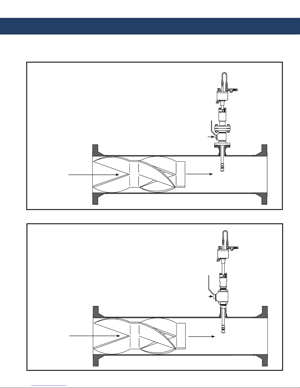
FIG. 1-1
Option 1: Retractable IAS™
on a main pipe, with 2”, 3”, or 4” anged seal housing
Full-opening Ball Valve
Recommended
KAM® SMS™
Static Mixing Spool
FIG. 1-2
Option 2: Retractable IAS™
on a main pipe, with 1 1/4" or 2" MNPT seal housing
Q
Full-opening Ball Valve
Recommended
KAM® SMS™
Static Mixing Spool
IASMANUAL 0514
Q
2
KAM CONTROLS, INC.
Page 4
INTRODUCTION CONTINUED
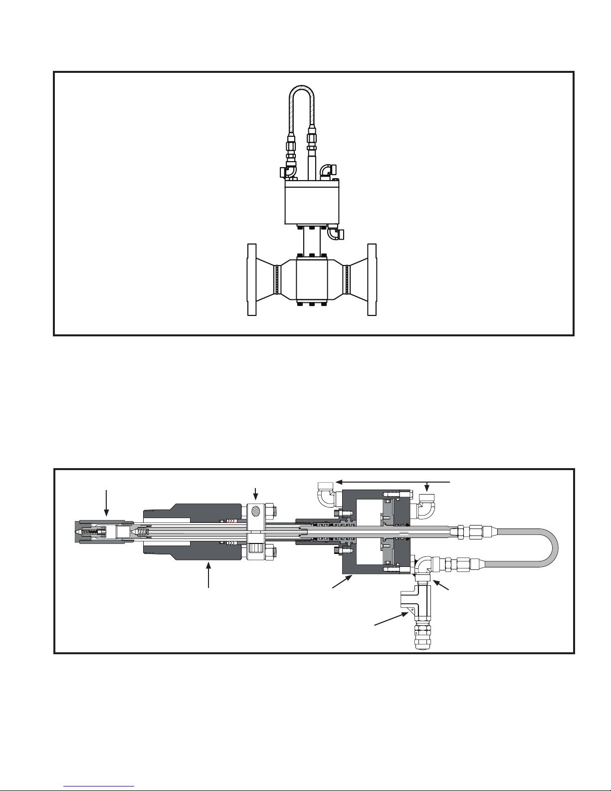
FIG. 1-3
Option 3: IAS™ FT
Flow Through with
2" 150# anges
THEORY OF OPERATION
Employing the simplest design in the industry, the KAM® IAS™ Isokinetic Automatic Sampler is the ideal instrument
for pipeline sampling during custody transfer. The IAS™ sampler is designed to extract a representative sample
of the pipeline into a KAM® SR™ Sample Receiver. With a KAM® CSM™ Circulating Sample Mixer, you may then
mix and analyze the sample for custody transfer, API gravity measurements, shrinkage, chemical composition, etc.
FIG. 1-2
Sampling Chamber
Locking Collar
Seal Housing
Actuator Housing
Pressure Relief Valve
Air Inlets
Sample Outlet
IASMANUAL 0514
3
KAM CONTROLS, INC.
Page 5

INTRODUCTION CONTINUED
FEATURES
• User friendly
• Positive displacement design
• Pneumatic, hydraulic
• Insertable and extractable through
full-opening ball valve
• Fast loop and main line models
• Variable insertion
• Simple design
• Isokinetic
• Pressure relief valve
SAMPLER SEQUENCE
FIG. 1-3
APPLICATIONS
• Custody transfer
• Marine loading, unloading, lightering
• Pipeline
• Truck loading, unloading
• Production
• Renery
• Power plant fuel oil
• Research
• Quality control in
IASMANUAL 0514
4
KAM CONTROLS, INC.
Page 6

SPECIFICATIONS
Media: Crude oil, rened products, chemicals, water and wastewater
Wetted parts: 316 stainless steel shaft and probe cage
304 stainless steel sample piston
Teon sample chamber seal
Fluid temperature: -40º to 350ºF (-40º to 177ºC)
Power: Air pneumatic, hydraulic
Sample size: 0.5 ml - 3 ml (Please specify)
Repeatability: Exceeds API 8.2
Mounting: Main line - 1¼" MNPT, 2" MNPT seal housing,
or 2", 3", or 4" anged seal housing
Fast loop - ¼" FNPT
Pressure ratings: ANSI 150, 300, 600, 900
Probe dimensions: Ø1.25" x 3.1" (32mmh x 79mm)
Shaft length: 30" (762mm) Other sizes available
REQUIREMENTS
Air: 70 to 125 psi
Consumption: 20 cubic inches per stroke
Minimum Sample Time: 1.5 seconds
IASMANUAL 0514
5
KAM CONTROLS, INC.
Page 7
INSTALLATION
PRIOR TO INSTALLATION
Before installing the IAS™ Sampler, make sure that it was not damaged during transit.
KAM CONTROLS recommends that the IAS™ Sampler be installed 2 to 4 pipe diameters downstream of a
KAM® static mixer or ow conditioner. At the time of installation the pipeline pressure needs to be reduced to
under 100 psi in order to be able to install the IAS™ Sampler.
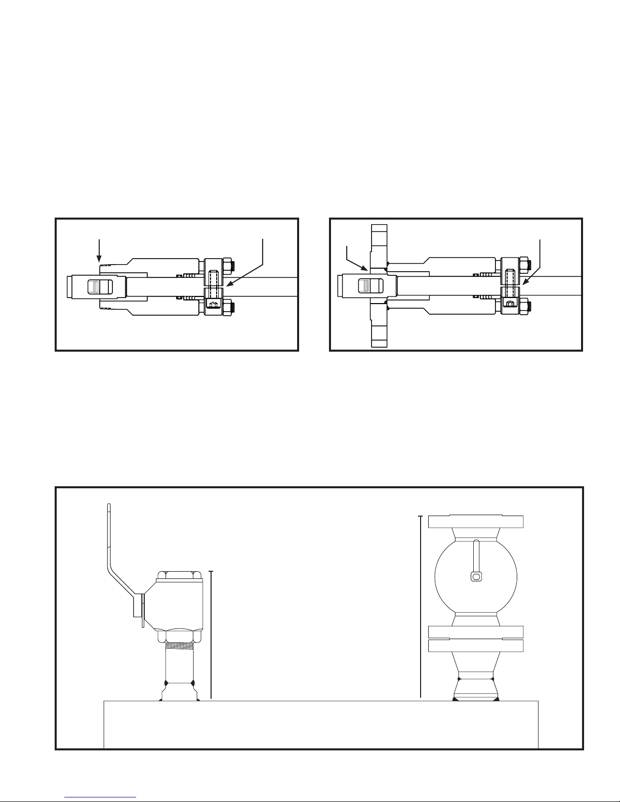
The IAS™ Sampler should be installed horizontally at 3 or 9 o’clock. Fig. 3-1.
The IAS™ Sampler Probe should be inserted so that the middle of the sampling window is in the 20% center
area of the pipe. Fig. 3-1.
MAIN LINE INSTALLATION
Before mounting the IAS™ Sampler on the Full-Opening Ball Valve, determine the insertion length required.
The IAS™ Sampler should be installed according to Fig. 3-1. The Full-Opening Ball Valve is used to isolate the IAS™
Sampler from the pipeline during installation or removal. The Seal Housing of the IAS™ Sampler allows the Sampler Probe to be inserted in and out of the pipe under pressure and ow conditions up to 100 psi. It is the user’s
responsibility to ensure that the IAS™ Sampler is placed in the most representative point in the ow prole. Prior
to installation, make sure you have the correct Pressure Relief Valve. The IAS™ Sampler is normally shipped with
a PRV designed for pressures up to 750 psi. If the line pressure is greater than 750 psi, please replace the spring
inside the PRV with the appropriate Spring. See Table 3-2.
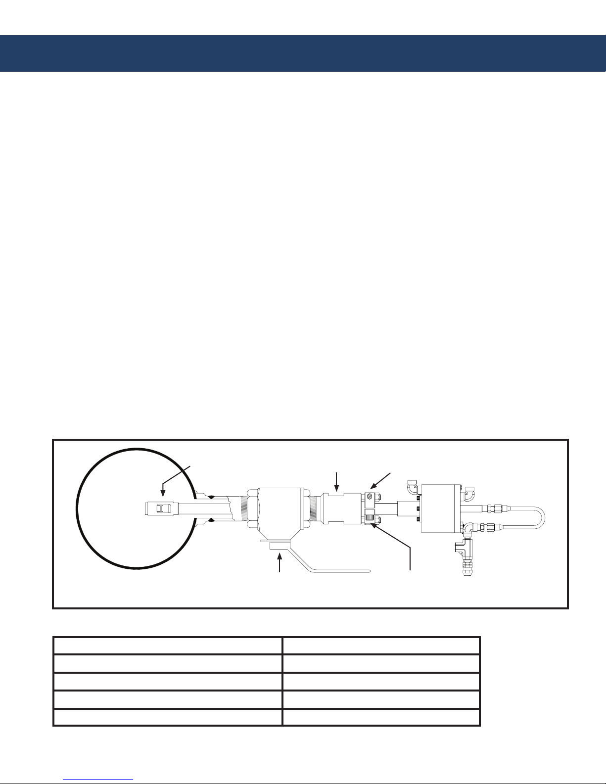
FIG. 3-1 END VIEW OF A KAM® IAS™ INSTALLED ON A MAIN PIPE
Sampler Probe
Seal Housing
Full-opening
Ball Valve
TABLE 3-2
PRV Spring Cracking Pressure Range (psig) Spring Color
50 to 350
350 to 750
750 to 1500
1500 to 2250
Blue
Yellow (included with IAS™ Sampler)
Purple
Orange
Locking Collar
Hex Socket Cap
Screw
IASMANUAL 0514
6
KAM CONTROLS, INC.
Page 8
INSTALLATION CONTINUED
1.
Lay the IAS™ Sampler on the ground or a table.
Loosen Hex Socket Cap Screws on the Locking Collar. Fig. 3-1. This will allow the IAS™ Sampler Shaft to slide
2.
through the Seal Housing.
3.
Push the IAS™ Sampler Shaft though the Seal Housing until the middle of the sampler window chamber is
aligned with the end of the Seal Housing. Fig. 3-3 or Fig. 3-4.
4.
Use a Sharpie or other permanent marker to mark the shaft at the edge of the Locking Collar. (Do not use anything sharp to mark the shaft. This will create grooves that will damage the O-rings in the Seal Housing.)
FIG. 3-3 MNPT SEAL HOUSING
Mark HereAlign Here
Pull Shaft back until the Probe is all the way in the Seal Housing and tighten the Hex Socket Cap Screws on the
5.
FIG. 3-4 FLANGED SEAL HOUSING
Align
Here
Mark Here
Locking Collar. This will prevent the IAS™ Sampler Shaft from sliding and the Probe will be protected inside
the Seal Housing.
6.
Measure the distance (D1) from the top of the main pipe to the end of the connection where the IAS™ Sampler
is going to be installed. Fig. 3-5.
FIG. 3-5
IASMANUAL 0514
D1 D1
7
KAM CONTROLS, INC.
Page 9
INSTALLATION CONTINUED
Calculate the insertion distance using the following formula:
7.
TID – Total Insertion Distance
D1 – Distance from the top of the valve to the pipe
WT – Pipe Wall Thickness
TD – Threaded Depth
ID – Inside Diameter
For Flanged Seal Housing
Total Insertion Distance (TID)= D1 + WT + (Pipe ID x 7/16) + Seal Thickness
Example: D1= 14"
WT= .25"
ID = 8.125"
Seal Thickness=1/8"
TID=14 + .25 + (8.125 x 7/16) + 1/8
TID=14 + .25 + 3.55 + .125= 17.93
For 2" MNPT Seal Housing
TID cannot be calculated until the Seal Housing is screwed into place. Bolt or Screw the IAS™ Sampler to the
Valve or designated installation location. (KAM CONTROLS recommends liquid thread sealant and not teon
tape for the threaded IAS™ Sampler.)
You must then measure the Threaded Depth (TD) into the Valve or connection in order to calculate TID. You can
do this by measuring the distance from the edge of the Valve or female connection to the top of the Seal Housing body and subtracting that distance from 5.25". Fig 3-6.
Total Insertion Distance (TID)= D1 + WT + 7/16 Pipe ID -Threaded Depth (TD)
FIG. 3-6
Threaded Depth
Measuring Points
For example: If the measured distance from the top of the Valve and the top of the Seal Housing body is 4.65"
you should calculate the threaded depth (TD) by subtracting 4.65" from 5.25". (5.25-4.65=0.6)
In this case the threaded depth (TD) would be .6"
IASMANUAL 0514
8
KAM CONTROLS, INC.
Page 10

INSTALLATION CONTINUED
You are now ready to calculate the TID.
TID= D1 + WT + (Pipe ID x 7/16) - TD
Example: D1= 14"
WT= .25"
ID = 8.125"
TD=.6"
TID=14 + .25 + 3.55 - .6=17.2
Use the Calculated TID and make another mark on the shaft, measuring from First Mark. Fig 3-7.
8.
FIG. 3-7
TID
First Mark Second Mark
If you have an IAS™ Sampler with a Flanged Seal Housing, you may now attach it to the Valve on the pipeline.
9.
Slowly open Full Opening Valve and check for leaks.
10.
Loosen Socket Head Screw on the Locking Collar.
11.
12.
Align Window of the IAS™ Sampler to face the owing stream. This can be done by aligning the Flow
Indicators in parallel with the main pipe. The Flow Indicators are located at the bottom of the Actuator
Housing.
Push the IAS™ Sampler in until the Second Mark is at the top edge of the Locking Collar. Fig. 3-8.
13.
FIG. 3-8
Second Mark
IASMANUAL 0514
9
KAM CONTROLS, INC.
Page 11

INSTALLATION CONTINUED
Re-tighten the Hex Socket Cap Screw.
14.
15.
Tighten the Hex Nuts holding the Locking Collar from ¼ to ½ of a turn. The Hex Nuts holding down the Locking Collar should never be over tightened. Their major function is to apply light pressure on the Chevron Packing to ensure a seal between the Seal Housing Body and the Insertion Shaft. Fig. 3-9.
FIG. 3-9
Locking Collar Hex Nuts
Hex Socket Cap Screw
The PRV arrives set at the maximum cracking pressure for the spring installed (normally a yellow spring for
16.
750 psi). If the maximum pressure does not exceed 350 psi, set the cracking pressure to the lowest cracking
pressure for the PRV by twisting the cap 8 turns counter-clockwise. The PRV is going to have the highest
cracking pressure when the cap is screwed all the way in and the lowest cracking pressure when the cap is
almost all the way out. If your line pressure is within the range of the cracking pressure of the PRV, take the
following steps to set the correct cracking pressure:
a) Slowly turn the cap counter-clockwise until liquid starts to come out of the PRV outlet.
b) Turn the cap two turns clockwise to stop the leak and set the PRV cracking pressure 200psi above the
current pressure.
c) Tighten lock nut against the cap.
d) Lock wire cap and body together to maintain set pressure.
Once you have set the PRV cracking pressure you are ready to make the eld air connections.
IASMANUAL 0514
10
KAM CONTROLS, INC.
Page 12

INSTALLATION CONTINUED
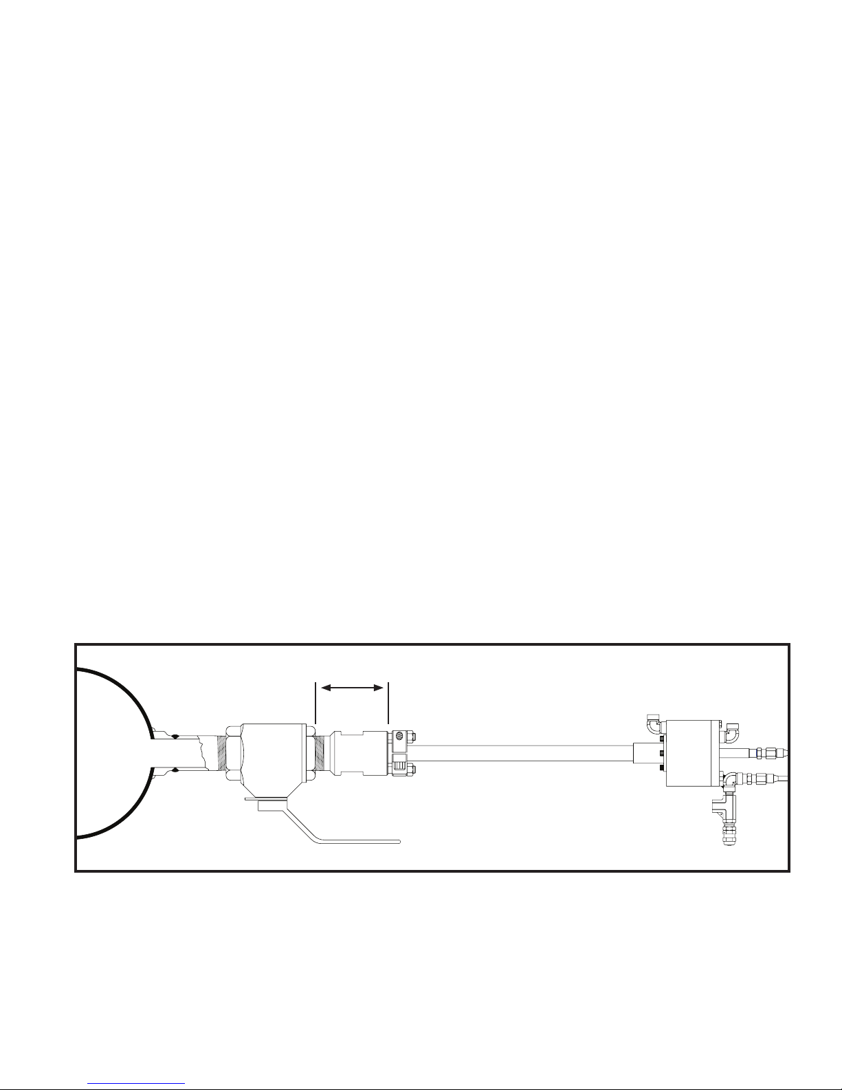
FIELD AIR CONNECTIONS
1.
Using Stainless Steel Tubing or Stainless Steel Braided Hose, connect the normally open port (usually marked
with a letter "A" or "NO") of the Solenoid Valve to the bottom of the Actuator Housing. Connect the normally
closed port (usually marked "B" or "NC") to the top of the Actuator Housing. Fig. 3-10.
Connect the Solenoid Valve Coil to a KAM® SC™ Sampler Controller according to the manual for the Solenoid
2.
Valve. The SC™ Controller should be programmed in a way that it energizes the coil for at least 1.5 seconds.
Every time the coil is energized and de-energized the IAS™ Sampler will take a sample.
Using a combination of ¼" Stainless Steel Tubing and Stainless Steel Braided Hose, connect the IAS™
3.
Sampler PRV outlet to the inlet of a Sample Container.
FIG. 3-10
Solenoid Coil to
Sampler Controller
Computer
EA
P
EB
Regulated
Air Supply
A
B
Sample Outlet
to Sample
Container
IASMANUAL 0514
11
KAM CONTROLS, INC.
Page 13

INSTALLATION CONTINUED
REMOVING THE IAS™ SAMPLER
Turn off the air supply going to the Solenoid Valve.
1.
2.
Disconnect the ¼" air connections going to the IAS™ Sampler Actuator Housing.
Disconnect the ¼" connection going to the IAS™ Sampler sample outlet.
3.
It is very important to depressurize the pipeline to below 100 psi. Ideally the pressure needs to be close to
0 psi. Failure to do so could result in injury or damage to the sampler.
4.
Once all the connections going to the IAS™ Sampler are removed, slowly loosen the Locking Collar by turning
the Hex Socket Cap Screws counter-clockwise. If there is pressure on the line, it will push the IAS™ Sampler
out when the Locking Collar is loose. If there isn’t enough pressure on the line, manually pull the IAS™
Sampler until the end of the probe stops inside the Seal Housing.
Tighten the Locking Collar by turning the Socket Cap Screws clockwise to prevent the IAS™ Sampler from
5.
sliding back in the pipeline or in the way of the Isolation Valve.
6.
Close the Isolation Valve.
Remove the IAS™ Sampler from the Isolation Valve.
7.
FIG. 3-11
Seal Housing
Isolation Valve
Locking Collar
Hex Socket Cap Screw
Actuator Housing
IASMANUAL 0514
12
KAM CONTROLS, INC.
Page 14

MAINTENANCE
During normal operation of the KAM® IAS™ Sampler, some seals will wear. In order to ensure continuous accurate sampling, KAM CONTROLS recommends replacing the seals on your IAS™ Sampler every six months.
A complete kit with all the IAS™ Sampler O-rings, seals, etc. can be order by contacting KAM CONTROLS at
sales@kam.com and requesting Seal Kit 91000 or by calling +1 713-784-0000 or faxing your request to
+1 713-784-0001.
FIG. 4-1
23
3
2122
4
1 2
TABLE 4-2 SEAL KIT 91000
ITEM
1
2
3
4
5
6
7
8
9
10
11
12
13
14
15
16
17
18
19
20
21
22
23
IASMANUAL 0514
DESCRIPTION
2-014 Viton O-ring
2-014 Teon Back-up ring
Conical Check
Check Spring
2-011 Viton O-ring
2-020 Viton O-ring
2-020 Teon Back-up ring
2-114 Viton O-ring
2-114 Teon Back-up ring
2-022 Viton O-ring
2-022 Teon Back-up ring
4300 Series Polypack
PSP-338A Seal
2-234 Neoprene O-ring
4615SH959 Wiper Seal
2-018 Neoprene O-ring
2-024 Viton O-ring
2-214 Viton O-ring
2-214 Teon Back-up ring
Teon Chevron Packing
Suction Relief Spring
Suction Relief Valve
Bottom Stop Teon Seal
19
PART #
91005
91021
90785
90786
91004
91012
91013
91017
91018
91014
91015
90230
91020
91019
90211
91016
91001
91007
91115
91110
90789
90788
90100
18
20 5
QTY
2
2
1
1
1
1
1
4
4
1
1
4
1
1
3
1
2
1
2
1
1
1
1
REPLACEMENT FREQUENCY
Biannually or every time maintenance is performed
Biannually or every time maintenance is performed
Only if damaged
Yearly or when damaged
Yearly
Yearly
Yearly
Biannually or every time maintenance is performed
Biannually or every time maintenance is performed
Biannually or every time maintenance is performed
Biannually or every time maintenance is performed
Biannually or every time maintenance is performed
Biannually or every time maintenance is performed
Yearly
Biannually or every time maintenance is performed
Every two years or if damaged
Biannually or every time maintenance is performed
Biannually or every time maintenance is performed
Biannually or every time maintenance is performed
Biannually or every time maintenance is performed
Yearly
Only if damaged
Biannually or every time maintenance is performed
13
6 7
8 9
15
1617
98
12
1110
13
KAM CONTROLS, INC.
15
14
Page 15

MAINTENANCE CONTINUED
TAKING THE IAS™ SAMPLER APART TO REMOVE THE SEALS
To perform maintenance the IAS™ Sampler rst needs to be removed from the pipeline according to the
1.
instructions in Section 3, page 11.
2.
Once you’ve removed your IAS™ Sampler from the pipeline, clean all surfaces as much as possible.
3.
Place the IAS™ Sampler on a clean work surface and loosen the Locking Collar by turning the Hex Socket Cap
Screws counter-clockwise. Fig. 4-3.
Slide the Seal Housing back until the Sampling Chamber is completely exposed.
4.
Remove the Sampling Chamber from the shaft using a 1 1/8” wrench on the wrench at and turning it counter-
5.
clockwise. Fig. 4-3.
FIG. 4-3
Locking Collar
Sampling Chamber
Wrench Flat
Sampling Chamber
Seal Housing
Hex Socket Cap Screws
6.
Retighten the Hex Socket Cap Screws. Using the wrench at on the on the seal housing, turn the Seal Housing and Outer Shaft in a counter clockwise direction to unscrew them from the Seal Chamber. WARNING:
DO NOT use a pipe wrench on the Outer Shaft as this could damage the shaft and Sample Tube, prohibiting
sampling motion. Slide Seal Housing and Outer Shaft off Sampling Tube. Fig. 4-4.
FIG. 4-4
Seal Housing
Outer Shaft
IASMANUAL 0514
14
KAM CONTROLS, INC.
Page 16

MAINTENANCE CONTINUED
7.
Loosen Hex Socket Cap Screws once again and slide Seal Housing off Outer Shaft. Fig. 4-5.
FIG. 4-5
Seal Housing
Outer Shaft
FIG. 4-6
8.
Remove the (4) ¼” Socket Set
Screws holding the Seal Chamber to
Actuator Housing
the Actuator Housing using a 3/16"
allen wrench. Fig. 4-6.
Seal Chamber
¼" Socket
Set Screws
9.
Pull Seal Chamber away from the Actuator Housing and completely off the Sample Tube. Normally, Seal
Bushing # 1 will slide with the Seal Chamber down the Sample Tube until it hits the Sample Piston. Pull the
Seal Chamber free of Seal Bushing #1. Seal Bushing #2 will either remain against the Actuator Housing, or
slide down the Sample Tube with Seal Bushing #1. Fig. 4-7.
FIG. 4-7
Seal Bushing
Seal Chamber
IASMANUAL 0514
Sample Piston Sample Tube
#1
15
Seal Bushing
#2
Piston
Actuator
Tube
KAM CONTROLS, INC.
Page 17

MAINTENANCE CONTINUED
9.
Remove the Sample Piston by turning it counter-clockwise using a 5/8” wrench. Fig. 4-8.
10.
Slide Seal Bushing #1 off the Sample tube. Fig. 4-8. If Seal Bushing #1 did not slide free of the Actuator Housing
when you removed the Seal chamber, you can remove it when you disassemble the Actuator Housing. Fig. 4-9.
11.
If Seal Bushing #2 slid free of the Actuator Housing when you removed the
Seal chamber, slide it off the Sample
Sample Piston
Seal Bushing
#1
Tube. If not, it will be removed when
the Actuator Housing is disassembled.
Fig. 4-9.
6.
FIG. 4-8
Conical Check
12.
Remove (6) ¼" Bolts from the Actuator Housing using a 7/16" nut driver/wrench, including the two bolts an-
Check Spring
choring the Sample Outlet Plate to the Actuator Housing. Fig. 4-9.
Using a 1/2" wrench, remove 1/8” NPT Male Adapter on the Sample Outlet Tube from the Piston Actuator
13.
Tube. Fig. 4-9.
FIG. 4-9
Air Inlets
(4) ¼”-20 x 1” Bolts
Sample
Tube
Sample Tube
Sample Outlet Plate
Piston
Actuator
Tube
1
8
" NPT Male Adapter
(2)¼"-20 x 1 ¼" Bolts
IASMANUAL 0514
16
KAM CONTROLS, INC.
Page 18

MAINTENANCE CONTINUED
14.
Remove Actuator Housing Lid by pushing the Sample Tube toward the Actuator Housing. The Actuator Housing
Lid should lift off the housing body. If you are unable to push the lid off the Actuator Housing by hand, this can
be done by forcing compressed air into the Air Inlet on the Actuator Housing. CAUTION: Stand clear of the
end of the housing. Fig. 4-10.
15.
Slide Piston Disk Assembly and Sampling Tube completely free of the Actuator Housing. Fig. 4-10.
16.
Slide Seal Bushing # 2 from the inside of the Actuator Housing if it did not come out on step 10. Fig. 4-10.
FIG. 4-10
Piston
Actuator
Sample tubeSeal Bushing # 2
Tube
Actuator
Housing Lid
Piston Disk Assembly
17.
Remove (4) 6 3-2 * 1/2 Flat Head Phillips Screws in Piston Disk Spacer. Fig. 4-11. Unscrew Piston Disk from
Piston Actuator Tube and slide off.
FIG. 4-11
6 3-2 * 1/2 Flat Head Phillips Screws
Piston Disk Spacer
IASMANUAL 0514
17
Piston Disk
KAM CONTROLS, INC.
Page 19

MAINTENANCE CONTINUED
REPLACING THE SEALS AND O-RINGS
1.
Remove the bottom Stop from the Sampling Chamber by unscrewing it. Fig. 4-11.
Clean as necessary.
2.
Remove the Top from the Bottom Stop. To do so, use a 5/32 hex wrench and
3.
turning it counter clockwise. Replace the Teon Seal. Fig. 4-11.
Replace Top in Bottom Stop, then place a drop of Loctite 242 on Bottom Stop threads, and screw Bottom Stop
4.
back into the Sampling Chamber. Fig. 4-11.
FIG. 4-11
Bottom Stop
Sampling Chamber
Teon Seal
Top to Bottom Stop
Replace the PSP seal from the exterior
5.
of the Piston Disk. Replace 2-018 O-ring.
Fig. 4-12.
IASMANUAL 0514
FIG. 4-12
PSP Seal
18
O-ring (2-018)
KAM CONTROLS, INC.
Page 20

MAINTENANCE CONTINUED
On Seal Bushing #1 remove worn Wiper Seal, O-rings and Teon Backups using a small pick or screwdriver.
6.
Insert the rst replacement Teon Backup by squeezing it into an oblong shape and pushing it through the
center of the Seal Bushing until it catches inside the back groove. Continue pushing the Backup into the groove
until it snaps into place. Then, using the same procedure, place an O-ring 2-114 directly in front of the Teon
Backup inside the same groove. Repeat the process for the second Teon Backup and O-ring, then replace the
Wiper Seal on the end of Seal Bushing #1. Fig. 4-13.
7.
On Seal Bushing #2, remove worn Wiper Seal and Polypack Seals using a small pick or screwdriver. Replacing the center Polypack Seals (2 and 3) rst. Squeeze the Polypack Seal into an oblong shape and insert
through the end of the Seal Bushing until it catches on one of the two interior grooves. Polypack Seals are
directional. It is very important to install the center Polypack Seals with the O-ring/grooved side facing the
Wiper Seal end of the Seal Bushing according to Figure 4-13. Once you’ve installed the two center Polypack
Seals, replace their corresponding O-rings. Then replace the outer Polypack Seals (1 and 4) and )-rings in
the same way, making sure that Polypack Seal 4 on the end away from the Wiper Seal faces in the opposite
direction from the other three. Replace the Wiper Seal and the two outer O-rings.
FIG. 4-13
Wiper Seal (1)
O-ring 2-114 (2)
Teon Backup 2-114
O-ring 2-024 (2)Wiper Seal (1)
1 2 3 4
Polypack Seals
IASMANUAL 0514
19
KAM CONTROLS, INC.
Page 21

MAINTENANCE CONTINUED
Using the same method as in step 6 and 7,
8.
replace Teon Backups, O-rings and Wiper
Seal on the interior of the Actuator Housing Lid with the O-rings toward the interior
side of the lid and the Wiper Seal toward
the exterior. Then replace the large exterior O-ring (2-234) on the lid. Fig. 4-14.
FIG. 4-14
Teon Backups
Wiper Seal
Interior O-rings
Exterior O-ring
9.
To change the O-rings and Chevron Packing within the Seal Housing, rst remove the ½" Locking Nuts on the
end of the Seal Housing. Fig 4-15. Then remove the clamp and bushing. Replace the Teon Back-up Ring, Oring and Chevron Packing in the manner described in step 6.
FIG. 4-15
Chevron Packing Clamp
Teon Back-up Ring 2-214 O-ring 2-214 Bushing ½" Locking Nuts
IASMANUAL 0514
20
KAM CONTROLS, INC.
Page 22

MAINTENANCE CONTINUED
Replace two back-ups and one O-ring (2-014) from Sample Piston. Fig. 4-16.
10.
FIG. 4-16
Sample Piston
O-ring and back ups
11.
Replace the two O-rings and two back-ups in the Seal Chamber using the method desribed in step 6. Fig. 4-16a.
FIG. 4-16a
Teon Back-up Ring
and O-ring 2-020
Teon Back-up Ring
and O-ring 2-022
IASMANUAL 0514
21
KAM CONTROLS, INC.
Page 23

MAINTENANCE CONTINUED
REASSEMBLING THE IAS™ SAMPLER
Slide Piston Disk back over Piston Actuator Tube and screw into place. Slide Piston Disk Spacer over tube from
1.
the opposite end and secure in place with 6 3-2 * 1/2 Flat Head Phillips Screws. Fig. 4-17.
FIG. 4-17
6 3-2 * 1/2 Flat Head Phillips Screws
Piston Actuator Tube
Piston Disk Spacer
Piston Disk
Slide Sample Tube and Piston Disk Assembly back into the Actuator Housing. Fig. 4-18.
2.
Slide Actuator Housing Lid onto Piston Actuator Tube and push into Actuator Housing until it snaps into place.
3.
Make sure you align the two Air Inlets in the appropriate positions to reattach to air supply. Fig. 4-18.
FIG. 4-18
Actuator Housing
Piston Disk Assembly Piston Disk Spacer Piston Disk
IASMANUAL 0514
Sample tube
Piston
Actuator
Tube
22
Actuator
Housing Lid
KAM CONTROLS, INC.
Page 24

MAINTENANCE CONTINUED
Coat the ends of the (6) ¼" Actuator Housing Lid bolts with Loctite 242. Using a " wrench, reattach the Ac-
4.
7
16
tuator Housing Lid and Sample Outlet Plate, making sure to use the (2) 1 ¼" bolts in the Sample Outlet Plate.
Tighten the 6 bolts gradually and evenly. Fig. 4-19.
Reconnect the Sample Outlet Tube to
5.
FIG. 4-19
the Piston Actuator Tube. This is easiest
if you rst remove the Male Adapter
(4) ¼”-20 x 1” Bolts
from the Compression Fitting. Wrap one
end of the Male Adapter in teon tape,
then screw it into the Piston Actuator
Tube using a ½" wrench and holding
the Piston Actuator Tube Shaft in place
with a " wrench. Then attach the
9
16
Piston
Actuator
Tube
Compression Fitting at the end of the
Sample Outlet Tube to the exposed end
of the Male Adapter. Fig. 4-19.
1
8
" NPT Male Adapter
(2)¼"-20 x 1 ¼" Bolts
Slide Seal Bushing #1 down into Seal Chamber, Wiper Seal end rst. Then put Seal Bushing #2 into Seal
6.
Chamber, Wiper Seal end rst. Fig. 4-20.
FIG. 4-20a FIG. 4-20b
Seal Bushing #1 Seal Bushing #2
Seal Chamber
IASMANUAL 0514
23
KAM CONTROLS, INC.
Page 25

MAINTENANCE CONTINUED
Slide Seal Chamber back onto the Sampling Tube until Seal Bushing #2 rests against the Actuator Housing.
7.
Reconnect the Seal chamber to the Actuator Housing using the (4)¼" Socket Screws
tightened gradually and evenly. Fig. 4-21.
FIG. 4-21
Actuator Housing
Seal Chamber
Put Loctite 242 on exposed threads of Outer Shaft, then slide Outer Shaft over Sampling Tube and screw into
8.
Sampling Tube
Seal Chamber, tightening by hand. Fig. 4-22.
FIG. 4-22
Outer Shaft
Loctite
Air Inlet
Sampling Tube
Seal Chamber
Force compressed air into the Air Inlet on the Actuator Housing Lid (FIG. 4-22) until the Sampling Tube extends
9.
outside the end of the Outer Shaft and the threads are visible. Fig. 4-23a.
Reassemble Sample Piston, putting the Conical Check back in place and slipping a new Spring over the top.
10.
Fig. 4-21a. Wrap teon tape on the threaded end of the Sampling Tube, then use a 9/16" wrench on the
wrench at located on the outside end of the Actuator Housing to hold the Sampling Tube in place, and screw
the Sample Piston onto the Sampler Tube. Fig. 4-23b.
FIG. 4-23a
Sample Piston
Sampling Tube
Conical Check
Spring
IASMANUAL 0514
FIG. 4-23b
24
Sampling Tube
Sample Piston
Wrench Flat
KAM CONTROLS, INC.
Page 26

MAINTENANCE CONTINUED
Force compressed air into the Air Inlet on the Actuator Housing to push the Sampler Tube back into place.
11.
Fig. 4-24.
FIG. 4-24
Air Inlet
12.
Slide the Seal Housing onto the Outer Shaft. Fig. 4-25.
Using Loctite 242 on the exposed threaded end of the Outer Shaft, reattach the Sampling Chamber to the
13.
Outer shaft. Fig. 4-25.
FIG. 4-25
Locking Collar
Outer Shaft
Sampling Chamber
Seal Housing
Hex Socket
Cap Screws
Slide the Seal Housing down until it rests against the Sampling Chamber and tighten into place issuing the Hex
14.
Socket Cap Screws in order to protect the sampling chamber during transport. Using the wrench at on the
Seal Housing, turn Seal Housing (and Outer Shaft) in a clockwise direction to fully tighten seal between Outer
Shaft and Seal Chamber. Fig. 4-26.
FIG. 4-26
IASMANUAL 0514
Seal
25
KAM CONTROLS, INC.
Page 27

MAINTENANCE CONTINUED
You are now ready to test the reassembled IAS™ Sampler.
Place the sampling end into a bucket of water. Force air through the air inlets to create the sampling piston
1.
action. Capture multiple samples in a beaker and measure for consistency.
FIG. 4-27
Air Inlet
Sample Outlet
2.
IASMANUAL 0514
Reinstall your IAS™ using the steps outline in section 3.
Water
26
KAM CONTROLS, INC.
Page 28

TROUBLESHOOTING
Problem: Poor sample draw or no sample
Solution: Double check Spring inside Sample Piston and the O-ring on the Bottom Stop and replace if broken or
worn.
Problem: Oil in air lines
Solution: Usually, this means that the Seals inside the Seal Bushings are worn out. Perform
standard maintenance. If problem persists, the Piston Tube may be scratched and will need to be replaced.
Problem: Piston’s not moving
Solution: Check air supply and solenoid valve
Problem: Oil leaking through Seal Housing
Solution: Perform routine maintenance replacing O-rings, Seals, etc.
IASMANUAL 0514
27
KAM CONTROLS, INC.
 Loading...