

Page 1

MANUAL VERSION 1.0
0 9 - 16
For the latest instruction manual updates and information on the entire Kam range visit:
www.kam.co.uk
Kam products are manufactured by: Lamba plc, Unit 1, Southfields Road, Dunstable, Bedfordshire, United Kingdom LU6 3EJ
Telephone: (+44) (0)1582 690600 • Fax: (+44) (0)1582 690400 • Email: mail@lambaplc.com • Web: www.lambaplc.com
If this product is ever no longer functional please take it to a recycling plant for environmentally friendly disposal.
Due to continuous product development, specifications and appearance are subject to change.
© Copyright Lamba plc. E&OE.
Energy SD300
Multicolour animation laser with SD card input for shows
Page 2
Thank you for purchasing this Kam product, we are sure that it will serve you for many years to come.
To optimise it’s performance, please read these instructions carefully to familiarise yourself with the basic operations of the unit.
Please retain them for future reference.This unit has been tested at the factory before being shipped to you. To prevent or reduce
the risk of electrical shock or fire, do not expose the unit to rain or moisture. To prevent a fire hazard, do not expose the unit to
any naked flame sources. Unplug this apparatus during lightning storms or if it is unlikely to be used for long periods of time.
When installing the unit, please ensure you leave enough space around the unit for ventilation. Slots and openings in the unit are
provided for ventilation to ensure reliable operation of the product and to protect it from overheating. To prevent fire hazard, the
openings should never be blocked or covered.
The unit is powered by the mains, always handle the power cable by the plug. Never pull out the plug by pulling on the cable.
Never touch the power cable when your hands are wet as this could cause an electric shock. Do not tie a knot in the cable. The
power cable should be placed such that it is not likely to be stepped on. A damaged power cable can cause a fire or give you an
electrical shock. Check the power cord periodicaly, if you ever find that it is damaged, replace it before using the unit again.
Contact your retailer for a replacement.
The voltage of the available power supply differs according to country or region. Be sure that the power supply voltage of the area
where this unit is to be used meets the requirements of the unit.
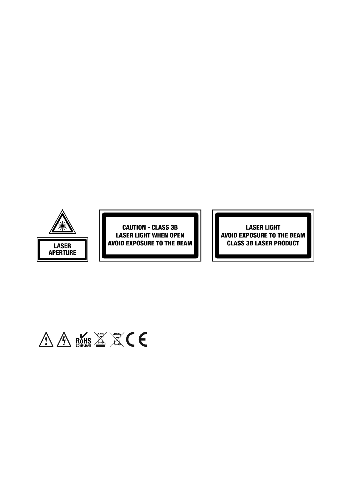
The lightning flash symbol inside a triangle is to alert the user to the presence high voltage within the unit’s enclosure
that may be of sufficient power to constitute a risk of electrical shock to persons. Caution: to prevent the risk of electric
shock, do not attempt to open the unit. No user-serviceable parts inside. Refer all servicing to qualified service
personnel. The exclamation mark inside a triangle is intended to alert the user to the presence of important operating
and maintenance instructions in the literature accompanying the appliance. Please read and pay attention to all laser
safety warning sticker labels on the unit.
Select the installation location of your unit carefully. Avoid placing it in direct sunlight or locations subject to vibration and
excessive dust. Do not use the unit where there are extremes in temperature (below 41ºF / 5ºC or exceeding 95ºF / 35ºC).
Unpacking and safety Please unpack your new product carefully. Your new product should reach you in perfect condition.
Please check that no damage has occurred during transit. If any damage is found, do not operate your unit. Please contact the
retailer you purchased it from immediately. If there is any damage to the mains cable do not use the device. Always disconnect
the unit from the mains supply when carrying out any cleaning of the unit.
Manufacturer declarations
In compliance with the following requirements: RoHS Directive (2002/95/EU) and WEEE Directive (2002/96/EU).
If this product is ever no longer functional please take it to a recycling plant for environmentally friendly disposal.
CE declaration of conformity
R&TTE Directive (1999/5/EU), EMC Directive (2004/108/EU), Low Voltage Directive (2006/95/EU).
The declarations are available on application from certification@lambaplc.com
Before putting the devices into operation, please observe the respective country-specific regulations.
This manual contains important laser system safety and operation information. Read and understand all instructions prior to
powering on the laser unit the first time to avoid eye injury and to avoid breaking the law. Keep this manual in a safe place for
future reference. Lasers can be hazardous and have unique safety considerations. Permanent eye injury and blindness is
possible if lasers are used incorrectly. Pay close attention to each safety WARNING statement in this manual.
Please refer to the Kam Class 3B Laser Product Safety Guide for more information on laser safety issues.
Page 3
Laser safety warnings…
Potential laser injury hazard exists with this product! Please read these instructions carefully, which include important information
about installation, safe use and service!
Caution Avoid direct eye contact with laser light. Never intentionally expose your eyes or others to direct laser radiation.
Caution It is illegal and dangerous to shine any laser at aircraft.
Caution Operating procedures other than those specified herein may result in hazardous radiation exposure.
Overhead rigging
Important - the installation must be carried out by qualified service personel only. Improper installation can result in serious
injuries and /or damage to property. Overhead rigging requires extensive experience. Working load limits should be respected,
certified installation materials should be used, the installed unit should be inspected regularly for safety.
l Make sure the area below the installation place is free from unwanted persons during rigging, de-rigging and servicing.
l Locate the unit in a well ventilated spot, far away from any flammable materials and/or liquids. The fixture must be fixed at
least 50cm from surrounding walls
l The device should be installed out of reach of people and outside of areas where persons may walk by or be seated.
l Before rigging make sure that the installation area can hold minimum point load of 10 times the device`s weight.
l The device should be well fixed; a free swinging mounting is dangerous.
l Do not cover any ventilation opening as this may result in overheating
Before using for the first time, the unit should be inspected for safety. Inspect the unit regularly every year.
AC power
The unit is supplied with a power plug appropriate to its voltage. Should any other connections be required they must be carried
out with the following configuration:
Cable (EU)
Cable (US)
Pin
International
Brown
Black
Live
L
Light blue
White
Neutral
N
Yellow/green
Green
Earth
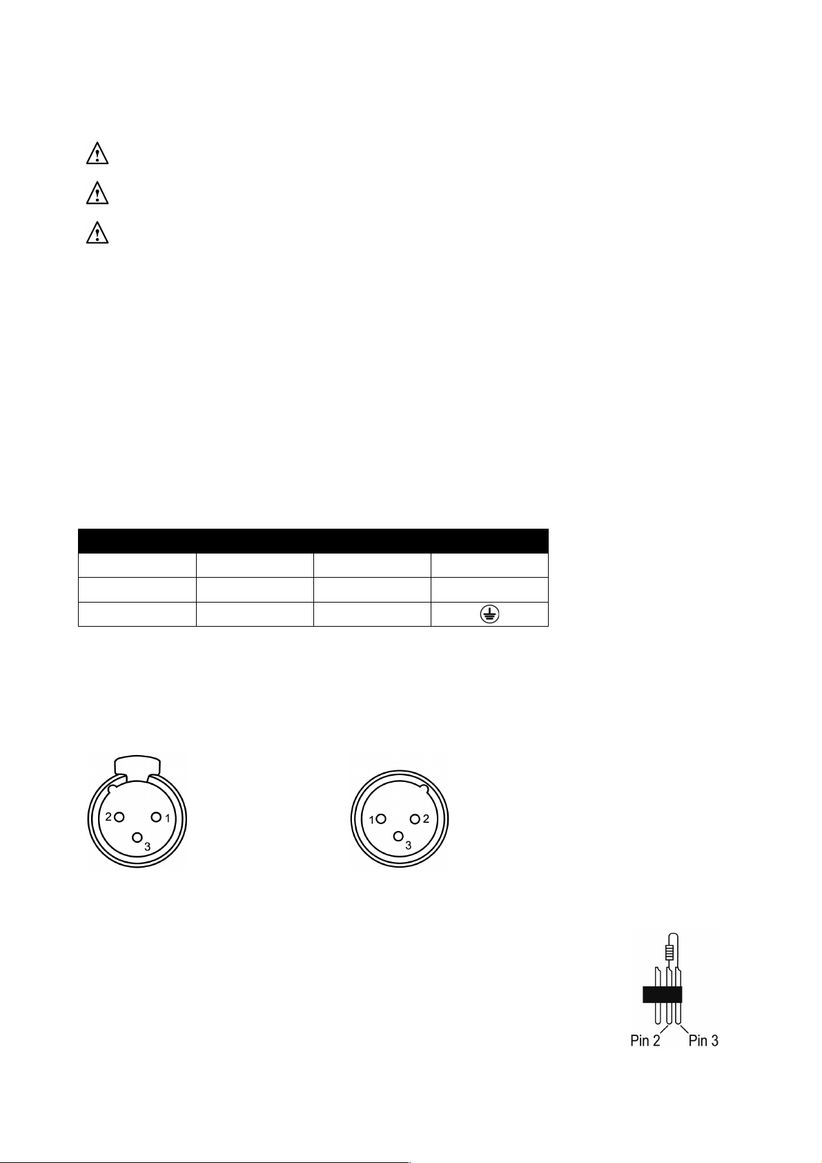
DMX-512 connection
If you are using a standard DMX controller, you can connect the DMX output of the controller directly to the DMX input of the first
unit in a DMX chain. If you wish to connect a DMX controller with other XLR outputs you will need to use adapter cables.
1 = Shield
DMX output 2 = Signal (-) DMX input
3 = Signal (+)
Connect the DMX output of the first unit in a DMX chain with the DMX input of the next unit in the chain. Always connect the the
output of one unit with the input of the next unit until all units are connected.
If you use a controller with 5 pin DMX connection you will need to use a 5 pin to 3 pin adapter.
Caution at the unit, the DMX cable has to be terminated with a terminator. Solder a 120 Ohm resistor
between Signal (-) and Signal (+) into a 3-pin XLR connector and plug this into the DMX output of the
last unit in the chain.
Page 4

What is included in the package
1 x Kam Energy SD300 laser unit
1 x IEC power cable
1 x safety key
1 x remote interlock key
1 x user manual
Front and Rear panels
Page 5

Front panel features
Number
Feature
Function
1
Laser aperture
The laser light is emitted from here. Never look directly into the hole when the unit is on
Rear panel features
Number
Feature
Function
2
Key lock
Supplied key switches the unit on and off
3
Remote interlock key
Safety feature - removal of remote interlock key shuts down all of the laser diodes
4
DMX out
3 pin female XLR connector for sending DMX signal
5
DMX in
3 pin male XLR connector for receiving DMX signal
6
Menu button
Selects menu functions from projected laser display
7
Microphone
Detects the music / sound signal
8
Micro SD card slot
Add an external micro SD card for additional laser shows
9
Menu UP button
Increases parameters in menu
10
Menu DOWN button
Decreases parameters in menu
11
Mains power
Mains power input with IEC socket and integrated fuse holder
12
IEC connector
Female IEC socket for connecting multiple units
13
Safety eyelet
Used to attach a safety chain when the unit is rigged
14
Cooling fan
Cooling fan – do not obstruct
Function Setting Menu
Please note that this unit’s operating menu is projected by the laser (it is not built into the unit), so it is suggested that the unit is
pointed at a single colour surface so the menu can be easily read. The size of the menu and text will be dependant on the how far
the unit is from the wall or surface. The size can also be adjusted using the Size setting within the menu (see below).
Main menu operation
Using the three function buttons (on the rear of the unit) you can set the operating mode of the unit. Press the Menu button to
display the different functions (see table below for a description of the functions). Use the Up or Down arrow buttons to make
your selection.
Function setting LED menu structure
Menu title
Function
AUDIO MODE
The unit will play built-in auto shows (in-air tunnel & beam effects) in time to any music playing
Use the UP or DOWN buttons to change the sensitivity of the microphone
AUTO MODE
Plays built-in auto shows (in-air tunnel & beam effects) in rotation
3CH: XXX or 14CH: XXX
This is the DMX setting menu - use the UP or DOWN buttons to change the DMX address
Alignment (big cross)
(Only when no SD card is inserted) - used by qualified engineers to align the laser diodes
SIZE: XXX
Use the UP or DOWN buttons to change the size of the projection from 10 (small) to 100 (big)
3CH MODE or 14CH MODE
Use the UP or DOWN buttons to choose between 3 or 14 channel DMX modes
PRG MODE
If a micro SD card is inserted, PRG mode will play all the ILD files that are in the selected folder
Press and hold the UP or DOWN buttons to move between the themed folders on the card
ILD MODE
If a micro SD card is inserted, ILD mode will play the first ILD file that is in the selected folder
Use the UP or DOWN buttons to move between the ILD files in each folder
Press and hold the UP or DOWN buttons to move between the themed folders on the card
Page 6

Micro SD card operation
If a micro SD card is inserted into the laser’s SD card slot, the following 2 modes will appear in the projected menu:
PRG MODE - program mode
This will play whatever ILD files are on the SD card (inside the first folder) in a rotation.
To ‘move up’ a folder, press and HOLD the UP button, this will move up to the next folder and then start playing the ILD files in
that folder in a rotation.
When the uppermost folder is reached, press and HOLD the DOWN button to move down the folders.
ILD MODE - ILD file mode
This will play whatever the first ILD file is on the SD card (inside the first folder). It repeats the same ILD file over and over. To
move to the next ILD file, you will need to press the UP button once (do not press and hold, just press once).
To ‘move up’ a folder, press and hold the UP button, this will move up to the next folder and then start playing the first ILD file in
that folder.
When the uppermost folder is reached, you need to press and hold the DOWN button to move down the folders.
How to add your ILD files to the SD card
If you internet search for ‘ILD files free’ you will find many websites that offer free downloads of laser animations and images that
you can add to your SD card and your shows. Many are themed around festivals and occasions (weddings, birthdays, xmas, etc).
To add the files to your micro SD card you will need to obtain a micro SD card reader (or an SD card reader and micro SD
adapter) for your computer. These are commonly available and very cheap to buy. Once you have loaded your micro SD card
onto your computer and can see the ‘contents’ of the card you will see that the card contains a series of folders with names like
‘Animals’, ‘Club’ and ‘Sports’. Inside each of these folders are a series of .ILD files as well as a single .PRG file.
The .ILD are the animation or image files.
The .PRG file contains information as to what is in each folder, enabling the unit to play the .ILD files.
To add your own group of .ILD files to your SD card, complete the following steps:
1. Somewhere on your computer, create a folder and name it with a simple, one word name like myshow1
2. Put your downloaded .ILD files inside your myshow1 folder.
3. Create a basic text file and name it with the exact same name as the folder. Add the suffix .PRG to the file. In our
example your text file should be called myshow1.PRG
4. Save this .PRG file into your myshow1 folder.
5. List the exact names of each of your .ILD files in the text file. For example if you have added 3 files named
‘Balloon.ILD’, ‘Cat.ILD’ and ‘Sun.ILD’ to your folder, the .PRG text file should first look like this:
Balloon.ILD
Cat.ILD
Sun.ILD
6. Next you need to add a play speed and a play figure. These are added to the names on your list and seperated by
commas. Your .PRG text file should now look like this:
Balloon.ILD,12,1
Cat.ILD,12,1
Sun.ILD,12,1
7. Save and close the myshow1.PRG file.
8. You should now have a folder called myshow1 containing three .ILD files and a .PRG file called myshow1.PRG
9. Copy this folder to the micro SD card. Do not put it inside any of the folders on the card, just add it to the other folders.
10. Eject the micro SD card and insert it into your unit, your new animations should appear amongst your other animations,
you will need to navigate to the folder using the methods listed at the top of this page.
Page 7

DMX address setting
When controlling lasers with a DMX controller, each unit must be set with a specific DMX address. When the laser receives a
signal, it will receive the channel control signal from the DMX512 controller.
You can choose to set multiple units with the same DMX address or you can set every unit with its own DMX address. If multiple
units are set with the same DMX address, they will receive DMX signal from this DMX address. If operated in this way, all units
will operate in the same way, you cannot control each unit separately. When using 14 channel mode, please note that several
optional operating modes were preprogrammed into the laser on DMX channel 1. Before controlling other DMX channels,
please ensure that CH 1 is set to the correct value.
3 channel DMX operation
Channel
Function
Value
Description 1 File select
0-255
Play files on SD card
2
File select
0-255
Play individual ILD files
3
Size/output
0-74
Laser OFF
75-255
Adjust image size from large to small
14 channel DMX operation
Channel
Function
Value
Description
1
Mode select
0-49
Auto mode
50-99
Audio mode (Sound-to-Light)
100-149
PRG mode
150-199
ILD mode
200-255
Manual DMX mode (CH1 must be set to this mode if you wish to use the functions below)
2
Pattern/folder select
(ensure CH1 is set to Manual DMX mode)
0-255
Manual mode
PRG/ILD mode
Pattern select, every 3 values = 1 pattern
File select
3
Flashing/file select
(ensure CH1 is set to Manual DMX mode)
0-10
No Strobe
Play file select
11-199
Auto strobe
200-255
Audio strobe
4
RGB colour mode select
(ensure CH1 is set to Manual DMX mode)
0-5
Laser OFF
6-16
White
Original colour
White
17-33
Red
34-50
Green
51-67
Blue
68-84
Yellow
85-101
Purple
102-118
Cyan
119-135
White, red, green, blue colour selection
136-152
Blue, yellow, purple, cyan colour selection
153-169
White, red, green, blue, yellow, purple, cyan colour selection
170-186
White, red, green, blue 4 colour flow
187-203
Blue, yellow, purple, cyan 4 colour flow
204-220
Blue, yellow, purple, cyan 4 colour flow
221-237
Colour subsection by inflexion
238-255
Sound activated colour change
5
X position
(ensure CH1 is set to Manual DMX mode)
0-125
Manually adjust X position
126-185
Moves circle from left to right automatically
186-255
Jumps circle from right to left automatically
226-245
Auto jumping
246-255
Sound activated jumping
Page 8

6
Y position
(ensure CH1 is set to Manual DMX mode)
0-125
Manually adjust Y position
126-185
Moves circle from up to down automatically
186-255
Jumps circle from down to up automatically
226-245
Auto jumping
246-255
Sound activated jumping
7
Zoom +/-
(ensure CH1 is set to Manual DMX mode)
0-10
No change
11-87
Manually adjust size
88-150
Zoom out continuously
151-200
Zoom in continuously
201-255
Zoom in and out continuously
8
Rolling X
(ensure CH1 is set to Manual DMX mode)
0
No change
1-128
Manual rotation
129-255
Auto rotation
9
Rolling Y
(ensure CH1 is set to Manual DMX mode)
0
No change
1-128
Manual rotation
129-255
Auto rotation
10
Rolling center
(ensure CH1 is set to Manual DMX mode)
0
No change
1-128
Manual rotation
129-192
Auto clockwise rotation
193-255
Auto anti-clockwise rotation
11
Drawing
(ensure CH1 is set to Manual DMX mode)
0-10
No change
10-74
Draw pattern manually
75-104
Auto drawing of pattern +
105-144
Auto drawing of pattern -
145-184
Auto drawing from start to finish
185-244
End to end drawing circle +
245-255
End to end drawing circle -
12
X wave
(ensure CH1 is set to Manual DMX mode)
0-9
No wave
10-69
Small wave
70-129
Medium wave
130-189
Large wave
190-255
Largest wave
13
Y wave
(ensure CH1 is set to Manual DMX mode)
0-9
No wave
10-69
Small wave
70-129
Medium wave
130-189
Large wave
190-255
Largest wave
14
Display mode
(ensure CH1 is set to Manual DMX mode)
0-63
Normal display of pattern
64-127
Light dot display of pattern
128-191
Segment display of pattern
192-255
Dot display of pattern
Product specification
Mains input / power consumption
AC100~240V, 50/60Hz / 14w
Control modes
DMX512 / Auto / Sound-to-Light / PRG / ILD
Scanner speed
10k
Laser power
Red: 150mW / 650nm Green: 50mW / 532nm Blue: 100mW / 450nm
Laser classification
Class 3B
Operating temperature
10~40°
DMX connections
3 pin XLR male/female
Dimensions (WxDxH) / Weight
190 x 165 x 118mm (not inluding bracket) / 1.8Kg
 Loading...