

Page 1
Mood Cluster
RGB LED wash effect with cluster & firework effects
9w RGB LED backwash effect with laser cluster and firework effects
Sound-to-Light, Auto, DMX and Master/Slave modes
8 channel DMX512 operation
XLR DMX in and out
Linkable Master/Slave in Sound-to-Light mode
40mW green laser / 100mW red laser
9w RGB LED wash effect
Numerous patterns available for selection
Fan cooled operation & tough metal chassis
Adjustable hanging bracket
Key operated power control
For the latest instruction manual updates and information on the entire Kam range visit:
www.kam.co.uk
Kam products are manufactured by: Lamba plc, Unit 1, Southfields Road, Dunstable, Bedfordshire, United Kingdom LU6 3EJ
Telephone: (+44) (0)1582 690600 • Fax: (+44) (0)1582 690400 • Email: mail@lambaplc.com • Web: www.lambaplc.com
If this product is ever no longer functional please take it to a recycling plant for environmentally friendly disposal.
Due to continuous product development, specifications and appearance are subject to change.
© COPYRIGHT LAMBA plc 2009. E&O E.
Page 2
INTRODUCTION
Thank you for purchasing the KAM LED Mood Cluster.
To optimise the performance of this product, please read these operating instructions carefully to
familiarize yourself with the basic operations of this unit. The KAM LED Mood Cluster has been designed
to create amazing laser effects. Please keep these user instructions in a safe place for future reference.
This unit has been tested at the factory before being shipped to you. There is no assembly required.
WARNING
To prevent or reduce the risk of electrical shock or fire, do not expose this unit to high temperature, rain or
moisture.
Unintended reflections of the laser beam from reflective or metallic surfaces can be dangerous. Do not
touch the laser aperture. When cleaning the laser Aperture, please use a soft cloth.
Laser Class 3B product. National regulations must be adhered to at all steps of installation. These can be
downloaded from the website www.kam.co.uk (In Germany apply DIN 56912 and BGVR LASER note:
additional regulations may apply).
Always replace the fuse with exact same type because anything other than the specified fuse can cause a
fire, electric shock, damage your unit, and will void your manufactures warranty. This appliance must be
earthed.
This appliance should be used by qualified personnel only.
UNPACKING YOUR NEW KAM PRODUCT
Carefully inspect your laser, as you unpack it. If any damage is evident, please notify the supplier you
purchased the unit from immediately. For safety reasons do not use the unit if any damage has occurred
during transportation.
CONTENTS: Laser, mains lead, user manual and safety keys.
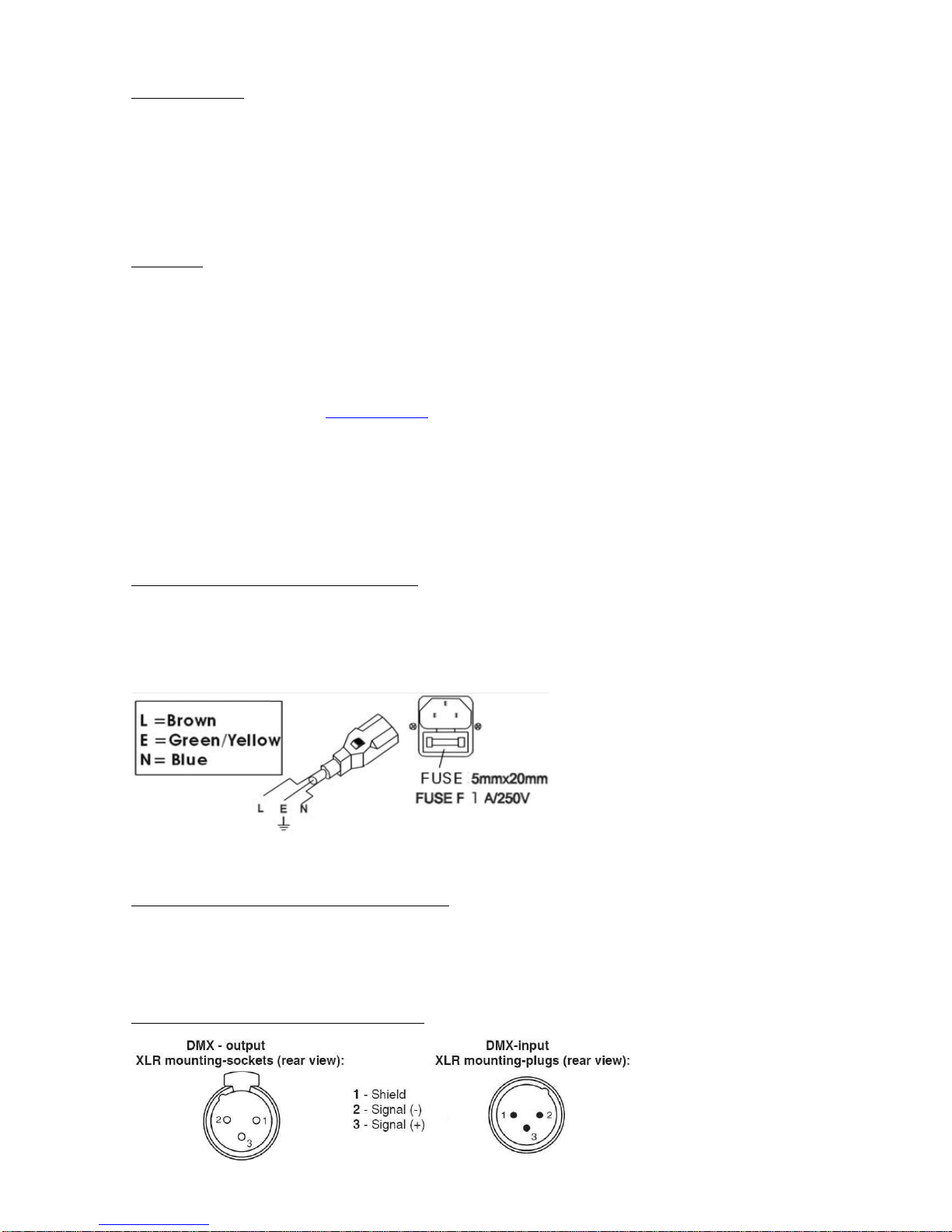
DMX-512 CONNECTION BETWEEN FIXTURES
The fixture is equipped with 3-pin XLR sockets for DMX input and output. The sockets are wired in
parallel. Only use a shielded twisted-pair cable designed for 3-pin XLR-plugs and connectors in order to
connect the controller with the fixture or one fixture with another.
OCCUPATION OF THE XLR-CONNECTION
Page 3
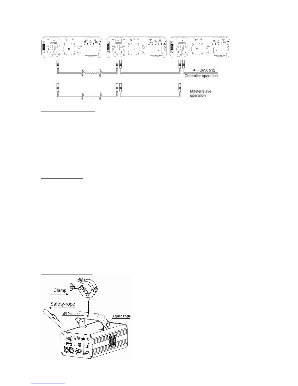
BUILDING A SERIAL DMX-CHAIN
Master / slave no controller
Set the master unit to desired effect, use the menu button, followed by the up and down buttons to select desired
master effect.
For example:
ASr
Auto mixed Slow laser effect with random order with manual control of led wash effect
Then press the enter button to confirm selection
To set slave unit
Use the menu button and the up/down button to select “SLA”
Press the enter button to confirm selection.
Both units will now react the same (only one master unit should be set as master all other units to be set as slave)
Using DMX controller
Each fixture needs to have a DMX start address to receive the data from the controller. The DMX address number,
which could be read from rear panel of each fixture and is between 000~511. Each unit uses 8 DMX channels.
If all units connected are to be controlled exactly the same, each unit must have the DMX start address set the same.
For example, set all units to channel 001.
Use the menu button and then the up/down buttons to select the desired DMX start address, press enter to confirm
your selection
Use a DMX cable to link the units together via the DMX in/out sockets on the rear panel. See above diagram.
Individual Control
To have DMX control over individual units each unit will need an individual start address. Each unit uses 8 DMX
channels.
As before using the menu button then up/down set the desired DMX address. For example, unit 1 set to 001 unit 2 set
to 009 etc. Adding 8 channels each time. Make sure no channels overlap.
Use a DMX cable to link the units together via the DMX in/out sockets on the rear panel. See above diagram
RIGGING THE FIXTURE
CAUTION: Please consider the respective national norms
during the installation! The installation must only be carried
out by an authorized employee or dealers! When installing
the device, make sure there is no highly in inflammable
material (decoration articles, etc.) in between a distance of
min 0.5m.
Page 4

FRONT PANEL
NO.
NAME
DESCRIPTION
1
Laser
Aperture
The laser effect output aperture.
NEVER LOOK INSIDE THE
FIXTURE THROUGH THIS
APERTURE WHILE FIXTURE
IS OPERATING.
2
LED Aperture
The LED effect output aperture.
REAR PANEL
NO.
NAME
DESCRIPTION
1
Main Power Input
IEC socket and integrated fuse holder.
2
Power Switch
ON and OFF switch
3
Key Switch
Safety key switch unit will not operate with this turned off
4
Interlock
Used to connect an optional emergency stop button. When the contact is closed the
laser will Black-out immediately. This must be wired by a qualified engineer
5
DMX input
3 pins male XLR connector
6
DMX output
3 pins female XLR connector
7
Microphone
To detect the music/sound signal
8
LED Speed
LED effect rotating speed
9
Mic Sensitivity Knob
Turning this knob clockwise increases the sound sensitivity
9
Mic Sensitivity Knob
Turn the knob (potentiometer) until the laser works in sync with the music.
10
Control Panel
To control the fixture with digital LED display, check more information on CONTROL
& FUNCTION
11
Cooling
Forced air fan cooling
12
Safety eyelet
Attach safety chain or rope to this point
OPERATING MODE
When laser is powered on, LED monitor on rear panel shows the current operating standalone mode or
DMX address of DMX mode. With help of LED control panel, it is very easy to set and change the
operating mode of laser. After every resetting and saved, the new mode information will be shown on LED
monitor at next power on.
Mode/Function Option, to choose the operating mode of laser.
Confirmation - to confirm all settings or change of LED control panel.
UP/DOWN, to change operating mode, parameter or DMX address.
Page 5

Standalone pre-programmed laser show
Press FUNC to enter the mode option. Keep pressing until the LED panel shows one of the following:
ArA, ASr, AFd, ASd, SrA, SSr, SFd, SSd.
Press UP or DOWN to select your favourite Standalone mode as above. Press ENTER to confirm the
setting. The laser is working in stand alone. Each time when you turn on your laser, it will default to this
setting.
In standalone mode, press the function button to choose a different program and the display will flash. Use
the up and down buttons to select the desired mode then press enter to confirm.
DISPLAY
STAND ALONE MODE LASER EFFECT
ArA
Mixed laser effect show automatic mode with manual control of led wash effect
Use led colour choice section to change led colour
ASr
Auto mixed Slow laser effect with random order with manual control of led wash effect
Use led colour choice section to change led colour
AFd
Auto Fast dot laser effect with manual control of led wash effect
Use led colour choice section to change led colour
ASd
Auto Slow dots laser effect with manual control of led wash effect
Use led colour choice section to change led colour
SrA
Sound activated rAndom mixed laser effect with manual control of led wash effect
Use led colour choice section to change led colour
SSr
Sound activated Slow random mixed laser effect with manual control of led wash effect
Use led colour choice section to change led colour
SFd
Sound activated Fast moving dots laser effect with manual control of led wash effect
Use led colour choice section to change led colour
SSd
Sound active Slow moving dots laser effect with manual control of led wash effect
Use led colour choice section to change led colour
LED colour choice
Press FUNC to enter mode option.
Keep pressing until the LED panel shows either one of LEd,Loo,rAn,-r-,-Y-,-G-, -C-, -b-, -P- & -W-.
colours explained in grid below.
Press UP or DOWN to select your favourite LED colour as above. Press ENTER to confirm the setting.
The LED will be in the colour which you selected. Each time you turn on your laser, it will default to this
colour option.
In the COLOUR CHOICE setting, the LED COLOUR that you are going to choose will flash. Press UP or
DOWN to change the LED colour, you will have 10 different LED colour modes. Their display and effects
are listed below:
DISPLAY
LED COLOUR
DISPLAY
LED COLOUR
LEd
LED Colour
-G-
Green
Loo
Colour Looping
-C-
Cyan
rAn
Colour Random
-b-
Blue
-r-
Red
-P-
Purple
-Y-
Yellow
White
Master/slave mode
Press FUNC to enter mode option. Keep pressing until the LED panel shows SLA. Press ENTER to
confirm the setting.
The laser is working in slave mode. Connect master laser and slave lasers with DMX cable, the SLAVE
lasers will do exactly what the master laser does.
DMX mode
Press FUNC to enter MODE OPTION
Until the LED panel shows 001.
Press ENTER to confirm the setting.
The laser is working in “DMX MODE”. With help of UP/DOWN button, change the number to the desired
DMX start address.
Page 6

DMX protocol
CHANNEL
DMX VALUE
DESCRIPTION
1 - MODE
000-025
Laser Black Out
026-050
Mixed laser effect Auto show with rAndom led
051-075
Auto mixed Slow laser effect with random led
076-100
Auto Fast dots laser effect
101-125
Auto Slow dots laser effect
126-150
Sound activated rAndom mixed laser effect
151-175
Sound activated Slow random laser effect
176-200
Sound activated Fast moving dots laser effect
201-225
Sound active Slow moving dots laser effect
225-255
DMX MODE
2 – ROTATION SPEED
AND DIRECTION
000-128
Anti-clockwise Rotation
129-138
Stop
139-255
Clockwise Rotation
3 - VIBRATE
000-255
vibrating Range
4 - FLASH
000-005
Stop
006-255
Flash
5 – COLOUR MODE
000-036
Black Out
037-072
Red
073-108
Green
109-144
Red & Green (To alternate colour use ch6)
145-180
Red and green, to strobe Green use ch6 also
181-216
Green and red to strobe red use ch6
217-255
Both Red and Green to strobe use ch6
6 - STROBE
000-127
NO Strobe
128-255
Speed of strobe
7 - LED COLOUR
MODE
To activate CH 7 –
CH8 value must be set to 4
000-025
No Strobe
026-050
White
051-075
Purple
076-100
Blue
101-125
Cyan
126-150
Green
151-175
Yellow
176-200
Red
To adjust speed use CH8
201-225
Looping Colour Strobing
226-255
Random Colour Strobing
8 - LED STROBE
000-003
NO Strobe
000-255
Fast to Slow
LASER EMISSION DATA
Laser Classification
Class 3B
Green Laser medium
DPSS Nd:YVO4, 532nm
Red laser medium
LD GaAlAs 650nm, typical
Beam diameter
<5mm at aperture
Pulse data
All pulses < 4Hz (>0.25sec)
Divergence (each beam)
<2 mrad
Divergence (total light)
<160 degrees
Laser Power
Red>100mW, Green>40mW
* As measured under IEC measurement conditions for classification.
LASER COMPLIANCE STATEMENT
This laser product complies with EN/IEC 60825-1 Ed 2, 2007-03, and US
FDA/CDRH FLPPS via the terms of Laser Notice No. 50 dated June 24, 2007.
Page 7

SPECIFICATIONS
Mains Input: AC100-240V, 50/60Hz
Fuse: 250V 1.6A Slow Blow (20mm Glass)
Total Power: 25W
Music Control: Internal microphone
Laser Power: 40mW 532nm Green CW
100mW 650nm Red CW
Laser Classification: Class 3B
Laser Safety Standard: EN60825-1 2007
Condition Temperature: 10~40℃
DMX Connections: 3 pins XLR Male/Female
DMX Channels: 8 channels
Measurement: See diagram below
N Weight: 2.8 Kg
 Loading...