

Page 1
5
5
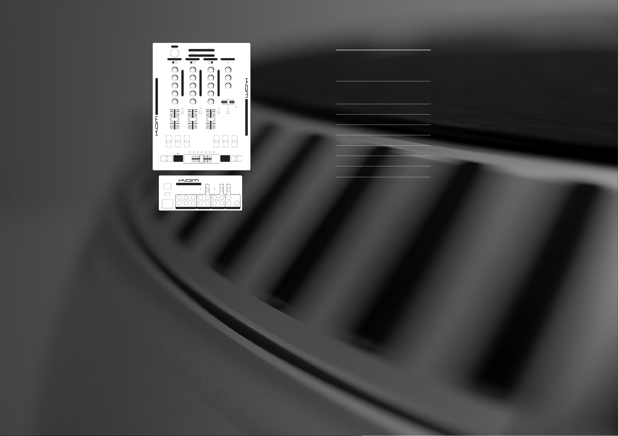
KAM SCRATCH PRO 150
PRO SCRATCH MIXER
INSTRUCTION MANUAL
SPECIFICATION
INPUT Mic 1mV / 600 Ohm
Phono 3mV / 50 Kohm
Line 150mV / 100 Kohm
OUTPUT Amp 1V / 600 Ohm
Rec 450mV / 600 Ohm
Headphone >8 Ohm stereo
FREQUENCY RANGE 20Hz~20KHz
EQ CONTROL -32dB /+10dB
THD 0.03%
S/N RATIO 70dB
POWER SUPPLY Internal
DIMENSIONS 272 x 400 x 100mm
WEIGHT 2.3Kg
Due to continuous product development, specifications are subject to change.
KAM SCRATCH PRO 150
PRO SCRATCH MIXER
e GROUND POSTS Use these to attach the ground wires
from your turntables. When using three turntables it is
advisable to avoid attaching all three ground wires to the
same ground post.
r OUTPUTS The unit has three outputs on the rear; 1 x
Master (unbalanced), 1 x Record (unbalanced) and 1 x Booth
(unbalanced). Connect the Master output to your amplifier. To
record your performances connect the record output to the
line input of your tape deck or MD. Connect the Booth output
to a DJ booth monitoring system if required.
t CHANNEL SELECTORS These are used to select the desired
input for each channel.
y GAIN CONTROLS Each music channel has a rotary gain
control. The Gain control adjusts the input level allowing the
user to reduce or increase the sound level to compensate for
quiet recordings.
u TONE CONTROLS Each channel has unique four band tone
controls, which can be used to cut and boost specific
frequencies. The bass control alters the level of lower Bass
frequencies, Mid 2 alters lower mid and higher Bass
frequencies, Mid 1 alters higher Mid frequencies and the Top
alters high frequencies. Turning the control clockwise boosts
the frequency. Turning the Tone controls fully anti-clockwise
utilizes the KAM KILL CUT feature which completely removes
the frequency.
i CUE SELECT BUTTON Pressing this button routes the
individual channel to the PFL/Headphone Cue system.
o CHANNEL LEVEL FADERS These are used to adjust the
output level for each channel.
1) FLASH KILL SWITCHES Each side of the crossfader has it’s
own set of 3 frequency band, 3 position, kill switches which
completely remove specific frequencies. Switch positions are;
Off, On (the switch says in position and kills the frequency)
and Flash (a sprung action which kills the frequency but when
released returns to the Off position).
1! 3-POSITION TRANSFORM SWITCHES These switches open
the channel and allow sound to pass to the master output,
regardless of the position of the crossfader. Switch
positions are; Off, On (the switch says in position and
opens the channel) and Flash (a sprung action which opens
the channel but when released returns to the Off position).
Designed for transform scratching type effects.
1@ BPM INDICATORS The KSP150 automatically calculates
the tempo of music playing through channels 2 & 3 and
displays the results on these screens. This information
helps you match the tempo of both channels.
1# BEAT OFFSET INDICATORS These LED’s help you
synchronise the beats of the music playing on channels
2&3. When the Green LED lights up both channels are
running at the same tempo, when the yellow LED lights up
both channels are almost running at the same tempo, when
the red LED lights up both channels are not running at the
same tempo.
1$ KAM PROFADE CROSSFADER This allows the user to mix
smoothly between both music channels. You are able to
adjust the curve of the crossfader with the crossfader
curve select switch.
1% CROSSFADER REVERSE SWITCH (Front of mixer) This
switch swaps which sides of the crossfader channels 2&3
are assigned to. This is useful for some scratch mixing
techniques.
1^ CROSSFADER OFF SWITCH (Front of mixer) This switch
disengages the crossfader entirely. When used all channels
are routed directly to the Master Output. This is useful for
some scratch mixing techniques.
1& MICROPHONE INPUT Use this socket to connect an
MC/DJ microphone. It will accept either an XLR or 1/4"
Jack type connector. NOTE: To maximize the performance
of this microphone channel check out the range of Mixer
Matched KAM Microphones.
1* MASTER OUTPUT LEVEL DISPLAYS These Meters show the
Left and Right levels of the Master Output of the mixer.
1( CHANNEL LEVEL METERS Each channel has it’s own Pre
Fade Level Meter which always shows the Level of the
incoming signal after the channel gain control but before
the channel fader.
2) POWER LED The Power On LED will show the current
status (lit = on). Ensure the mixer is turned off when
connecting external equipment.
2! BOOTH LEVEL CONTROL Use this control to adjust the
volume of music sent to an independent DJ booth monitoring
system via the rear panel booth output connections.
2@ MASTER LEVEL CONTROL This controls the overall output
from the mixer, via the master output connection to the PA
System.
2# SPLIT / PFL SWITCH This switch controls the way in which
the monitoring circuit works. In the PFL position any
individual channel whose ‘Cue’ button is depressed plays
back in stereo through both headphones. In the SPLIT
position what you hear in the headphones is determined by
the Cue Select Fader.
2$ CUE SELECT FADER This Controls what is monitored in the
headphones when the SPLIT/PFL button is in the SPLIT
position. With the cue select fader to the left you should
hear the output from any channel whose Cue select button is
depressed in both headphones and with the cue select fader
to the right you should hear the Master Output in both
headphones. With the cue select fader in the centre you
should hear a mix of both the PFL and the Master Output
(PGM stands for Program and means the signal arriving at
the Master Output).
2% CUE LEVEL This controls the output volume of the
headphones.
2^ HEADPHONE OUTPUT SOCKETS (Front of mixer) Use these
stereo TRS sockets to connect your headphones.
2& VOLTAGE SELECTOR The KSP200 is dual voltage (110 /
230). Please ensure the correct voltage is selected for your
country. Failure to set the correct voltage will cause damage
to the unit.
2* REPLACEABLE PROFADE CROSSFADER (not shown) You are
probably already aware that this mixer comes with a FREE
EXTRA KAM ProFADE crossfader. Crossfaders get more use
than any other part of a mixer so they are always the first
thing to wear out. They are also generally not guaranteed
and are a chargeable item. The Team at KAM think you
deserve more time to enjoy mixing and preparing to be a top
class artist before you need to reach in to your pocket to
pay for a replacement. So with two faders in the box,
compared to other brands you will have twice as much time
to enjoy this product.
© COPYRIGHT LAMBA plc 2003. E&O E.
OVERVIEW
The KAM SCRATCH PRO 150 mixer is designed to give the
DANCE DJ maximum flexibility and features for minimum cost.
This mixer combines all the features required while maintaining
a high level of build quality and specification.
DON’T BLOW IT!
• Always ensure that the mixer is turned off when making
connections.
• Care should always be taken to ensure that the correct
connections are made.
• Connecting a CD player to the Phono input or a turntable
to the Line input can cause damage to the unit.
• When connecting a turntable to the Phono input always
use the signal earth cable from the turntable to the
ground point on the mixer.
• Always use shielded signal cables to reduce hum and
background noise.
• Care should be taken that ALL input and output signal
levels are not excessive. Excessive signals can cause
damage to your Kam mixer, connected equipment and
your ears!
• When using the KSP150’s powerful Tone Controls,
particular care should be taken to ensure that signal
levels do not become excessive.
• For optimum audio quality and listening pleasure signals
should peak at around zero dB on PFL and output level
meters.
q INPUTS The Kam KSP150 is a 9 input mixer
(3 phono/5 line/1 mic). All three channels featrue RCA type
inputs which are switchable between line level (for CDs etc)
and phono level (for decks) connections. Channels 2&3 have
additional RCA type line level inputs. Channel 1 has an
additional 1/4" jack mic input. Use the accompanying Input
Selection Switches to choose between line or turntable input.
w INPUT SELECTION SWITCHES Use these switches in
conjunction with the front panel channel selectors t to choose
which combination of inputs is assigned to each channel.
q
q
q
t
w
e
r
y
u
i
o
1)
1!
1@
1#
1$
1&
1*
1(
2)
2!
2@
2%
2#
2$
2&
MIC
CHANNEL 1
GAIN
TOP
MID 1
MID 2
SCRATCH PRO 150
BASS
BASS MID TOP BASS MID TOP
ON
•
OFF
•
FLASH
•
KILL SWITCHES
---7-5-
-
-
-10 -7-5-
-
LINEMIC
LINEPHONO
+9
+6
+3
0
-3
-5
-7
-10
-15
-20
PFL PFL PFL
+9
GAIN
+6
+3
0
TOP
-3
-5
-7
MID 1
-10
-15
-20
MID 2
BASS
BPM
BEAT OFFSET
GAIN
TOP
MID 1
MID 2
BASS
OUTPUT
CROSSFADE
PHONO
GROUND GROUND
CD
CHANNEL 3
POWER
SCRATCH PRO 150
230V~/50Hz
MASTER LINE PHONO/CD
AC INPUT
+
+
LINEPHONO
+9
+6
+3
0
-3
-5
-7
-10
-15
-20
KILL SWITCHES
PHONO
CD
LINE PHONO/CD
CHANNEL 2
MASTER
POWER ON
BOOTH
MASTER
PHONES LEVEL
LINE MICBOOTH RECORD
CHANNEL 1
SPLIT
MIX
PHONO
CD
SCRATCH PRO 150
ON
•
OFF
•
FLASH
•
 Loading...