

Page 1
KAP1010
Professional 11 input / 19 inch rack mount mixer
2 phono + 8 line + 1 mic
4 channel + dedicated mic channel
Combi XLR / jack microphone input
Mic level control with 2 band EQ
7 point LED level meters
5 band master graphic EQ
Assignable crossfader
Master level fader & 50mm channel faders
Record & master outputs
Dimensions: 482 x 90 x 78mm (WxHxD)
M A N U A L V E R S I O N 2 .0
06- 05- 10
For the latest instruction manual updates and information on the entire Kam range visit:
www.kam.co.uk
Kam products are manufactured by: Lamba plc, Unit 1, Southfields Road, Dunstable, Bedfordshire, United Kingdom LU6 3EJ
Telephone: (+44) (0)1582 690600 • Fax: (+44) (0)1582 690400 • Email: mail@lambaplc.com • Web: www.lambaplc.com
If this product is ever no longer functional please take it to a recycling plant for environmentally friendly disposal.
Due to continuous product development, specifications and appearance are subject to change.
© COPYRIGHT LAMBA plc 2010. E&O E.
Page 2
Thank you for purchasing this product, we are sure that it will serve you for many years to come.
To optimise the performance of this product, please read these operating instructions carefully to familiarise yourself with the
basic operations of this unit. After you have read the instructions, please retain them for future reference.
This unit has been tested at the factory before being shipped to you. To prevent or reduce the risk of electrical shock or fire, do
not expose the unit to rain or moisture. To prevent a fire hazard, do not expose the unit to any naked flame sources. Unplug this
apparatus during lightning storms or if it is unlikely to be used for long periods of time.
When installing the unit, please ensure you leave enough space around the unit for ventilation. Slots and openings in the unit are
provided for ventilation to ensure reliable operation of the product and to protect it from overheating. To prevent fire hazard, the
openings should never be blocked or covered. Always handle the power cable by the plug. Never pull out the plug by pulling on
the cable. Never touch the power cable when your hands are wet as this could cause an electric shock. Do not tie a knot in the
cable. The power cable should be placed such that it is not likely to be stepped on. A damaged power cable can cause a fire or
give you an electrical shock. Check the power cord periodicaly, if you ever find that it is damaged, replace it before using the unit
again. Contact your retailer for a replacement. The voltage of the available power supply differs according to country or region. Be
sure that the power supply voltage of the area where this unit is to be used meets the required written on the unit.
The lightning flash symbol inside a triangle is intended to alert the user to the presence high voltage within the unit’s
enclosure that may be of sufficient power to constitute a risk of electrical shock to persons. Caution: to prevent the risk
of electric shock, do not attempt to open the unit. No user-serviceable parts inside. Refer all servicing to qualified
service personnel. The exclamation mark inside a triangle is intended to alert the user to the presence of important
operating and maintenance instructions in the literature accompanying the appliance.
Any modification carried out on the unit may invalidate the unit’s warranty. Select the installation location of your unit carefully.
Avoid placing it in direct sunlight or locations subject to vibration and excessive dust. Do not use the unit where there are
extremes in temperature (below 41ºF / 5ºC or exceeding 95ºF / 35ºC).
Unpacking and safety: Please unpack your new product carefully, your new product should reach you in perfect condition. Please
check that no damage has occurred during transit. If any damage is found, do not operate your unit. Please contact the retailer
you purchased it from immediately. If there is any damage to the mains cable do not use the device. Always disconnect the unit
from the mains supply when carrying out any servicing or cleaning of the unit. The serial number for this equipment should be
located on the rear or underside of the unit. Please make a note of this number as you will need it for your warranty, it is a good
idea to keep a copy of the serial number for your own records.
Page 3

OVERVIEW
The KAM KAP1010 mixer is designed to give the DANCE DJ, MOBILE DJ, KARAOKE ARTIST, PUBLIC HOUSE AND SMALL
CLUB INSTALLATION maximum flexibility and features for minimum cost. This mixer combines all the features required while
maintaining a high level of build quality and specification.
INPUTS
KAP1010 is a 11 input mixer (max of 9 inputs at any one time). All the music channels have two separate inputs being a
combination of Line/phono or Line/Line. The unit also features a dedicated microphone channel with bass and treble adjustments
and combination JACK and XLR socket inputs, sound adjustment is via shared 5 band EQ. Care should be taken when
connecting to the mixer that the correct connections are made. Connecting a CD player to the Phono input or a turntable to the
Line input can cause damage to the unit. When connecting a turntable to the Phono input always use the signal earth cable from
the turntable to the ground point on the mixer. NOTE: the line /phono switch above the input sockets must be set to phono and
always use shielded signal cables to reduce hum and background noise. The unit should always be switched off when connecting
cables.
OUTPUTS
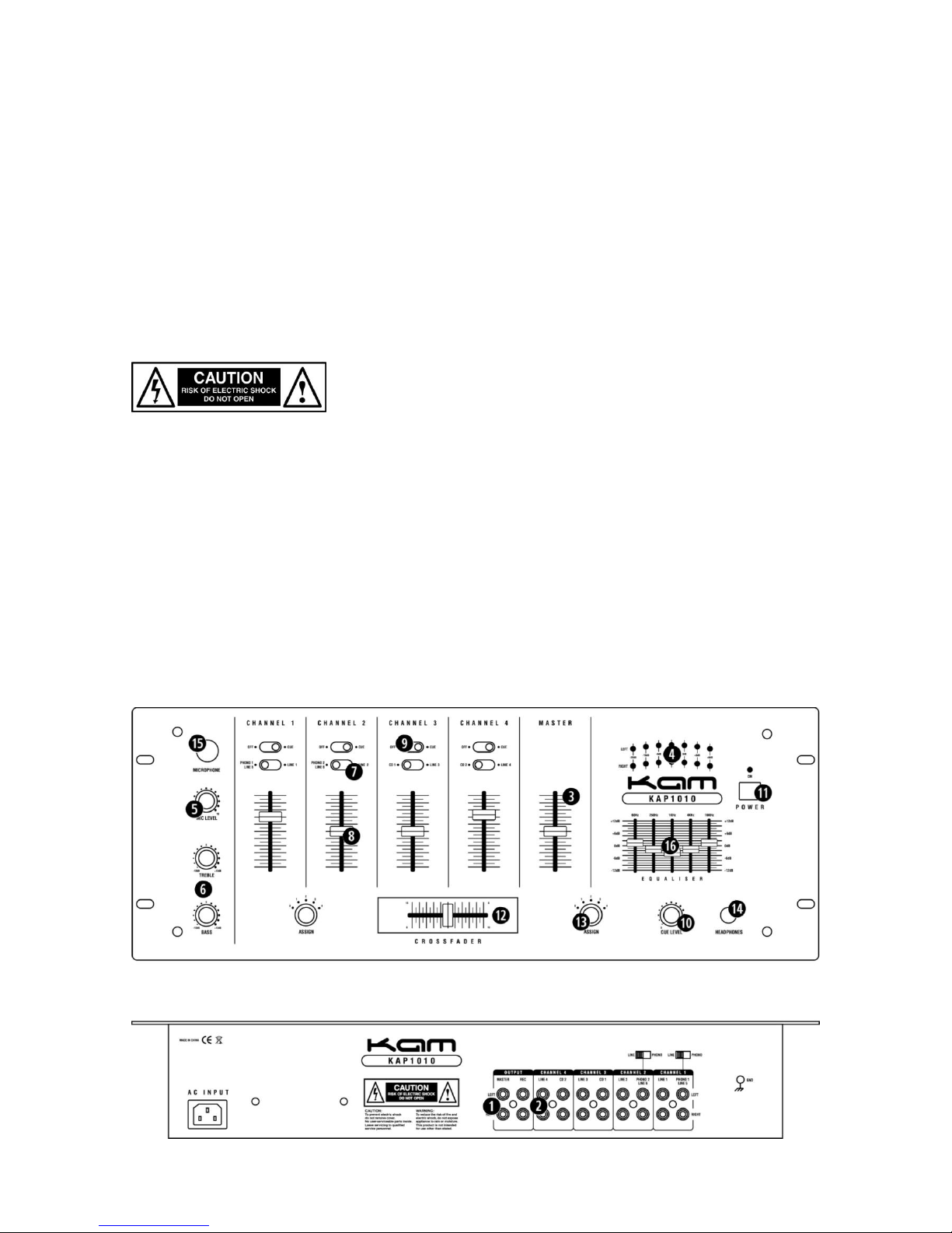
The unit has two unbalanced outputs on the rear, 1 x Record Output (2) and 1 x Master Output (1) These can be Connected to
either an external amplifier or tape deck. Care should be taken not to distort the output Signals above 0dB on the meters) as this
could cause damage to the external equipment.
MASTER OUTPUT CONTROL
(3) This controls the overall output from the mixer to the PA System. NOTE: care should be taken not to produce distortion with
these controls as this could result in damage to both the unit and any external equipment connected.
LED DISPLAYS
(4) The unit has two LED displays Left output, Right output The left and right output display shows the output level of the mixer.
MICROPHONE GAIN CONTROLS
(5) The microphone channel has a rotary gain control. The gain control adjusts the input level allowing the user to reduce or
increase the sound level. NOTE: care should be taken not to produce distortion with these controls as this could result in damage
to both the unit and any external equipment connected.
MICROPHONE TONE CONTROLS
(6) The microphone channel has a Bass, and treble control. The master Output also has five band tone controls. NOTE: Care
should be taken not to distort the output signal using these controls.
CHANNEL SELECTORS
(7) These are used to switch between Line / line input or Phono input on each channel.
CHANNEL LEVEL FADERS
(8) These are used to adjust the output level for each channel. NOTE: care should be taken not to produce distortion with these
controls as this could result in damage to both the unit and any external equipment connected.
PFL ASSIGN
(9) Each channel has a PFL assign switch. This should be activated when you wish to monitor that channel through the
headphone circuit.
PHONES LEVEL
(10) This controls the output volume of the headphones. Care should be taken not to have this set to high as it could result in
damage to both the hearing of the user and the headphones. The channel to be monitored is selected via the cue assign control
switch.
MICROPHONE CONTROLS
(5) The DJ/Mc or Vocalist microphone channel has its own dedicated gain control NOTE: To achieve the best results from the
microphone channel check out our range of Kam Mics.
POWER
(11) The Power On LED will show the current status (lit = on). Ensure the mixer is turned off when connecting external
Equipment.
KAM PROFADE CROSSFADER
(12) This allows the user to mix smoothly between both music channels selected on the crossfader assign.
Page 4

CROSSFADE ASSIGN
(13) To the left and right of the crossfader is a crossfade assign knob, which has an off position and selections 1-4. This control is
designed to assign the crossfade position to the appropriate channel. Crossfaders are generally not guaranteed and are a
Chargeable item.
HEADPHONES
(14) Headphone socket, connect the headphone to this socket to monitor the audio output of selected channels.
MICROPHONE INPUT (15)
GRAPHIC EQ (16)
SPECIFICATION
Input sensitivity
Phono 1 & 2 3mv
Mic 1.5 mv
Line / CD 150mv
Impedance
Phono 1&2 47 KOhms
Mic 600 ohm
Line / CD 47 KOhms
Output level 1.V
Harmonic distortion < 0.1%
Frequency response 20hz – 20 khz +/- 2db
S/N ratio >58 db
Headphone output 1.5v max / 16ohm
Power source 230v 50hz
Dimensions 482mm x 177mm x 105mm
Inputs 2 phono + 8 line + 1 mic
4 channel + mic input format
Mic input Combi XLR / jack microphone input
Microphone Mic level control with 2 band EQ
Metering 7 point LED level meters
Equalisation 5 band master graphic EQ
Crossfader Assignable
Faders Master level fader & 50mm channel faders
Outputs Record & master outputs
Dimensions 482 x 90 x 78mm (WxHxD)
 Loading...