

Page 1

MANUAL VERSION 1.0
August 2016
For the latest instruction manual updates and information on the entire Kam range visit:
www.kam.co.uk
Kam products are manufactured by: Lamba plc, Unit 1, Southfields Road, Dunstable, Bedfordshire, United Kingdom LU6 3EJ
Telephone: (+44) (0)1582 690600 • Fax: (+44) (0)1582 690400 • Email: mail@lambaplc.com • Web: www.lambaplc.com
If this product is ever no longer functional please take it to a recycling plant for environmentally friendly disposal.
Due to continuous product development, specifications and appearance are subject to change.
© Copyright Lamba plc 2014. E&OE.
Hyper3D 500
Spectacular multicolour laser that creates stunning 3D lightshows
Page 2
Thank you for purchasing this Kam product, we are sure that it will serve you for many years to come.
To optimise it’s performance, please read these instructions carefully to familiarise yourself with the basic operations of the unit. Please
retain them for future reference.This unit has been tested at the factory before being shipped to you. To prevent or reduce the risk of
electrical shock or fire, do not expose the unit to rain or moisture. To prevent a fire hazard, do not expose the unit to any naked flame
sources. Unplug this apparatus during lightning storms or if it is unlikely to be used for long periods of time.
When installing the unit, please ensure you leave enough space around the unit for ventilation. Slots and openings in the unit are provided
for ventilation to ensure reliable operation of the product and to protect it from overheating. To prevent fire hazard, the openings should
never be blocked or covered.
The unit is powered by the mains, always handle the power cable by the plug. Never pull out the plug by pulling on the cable. Never touch
the power cable when your hands are wet as this could cause an electric shock. Do not tie a knot in the cable. The power cable should be
placed such that it is not likely to be stepped on. A damaged power cable can cause a fire or give you an electrical shock. Check the power
cord periodicaly, if you ever find that it is damaged, replace it before using the unit again. Contact your retailer for a replacement.
The voltage of the available power supply differs according to country or region. Be sure that the power supply voltage of the area where
this unit is to be used meets the requirements of the unit.
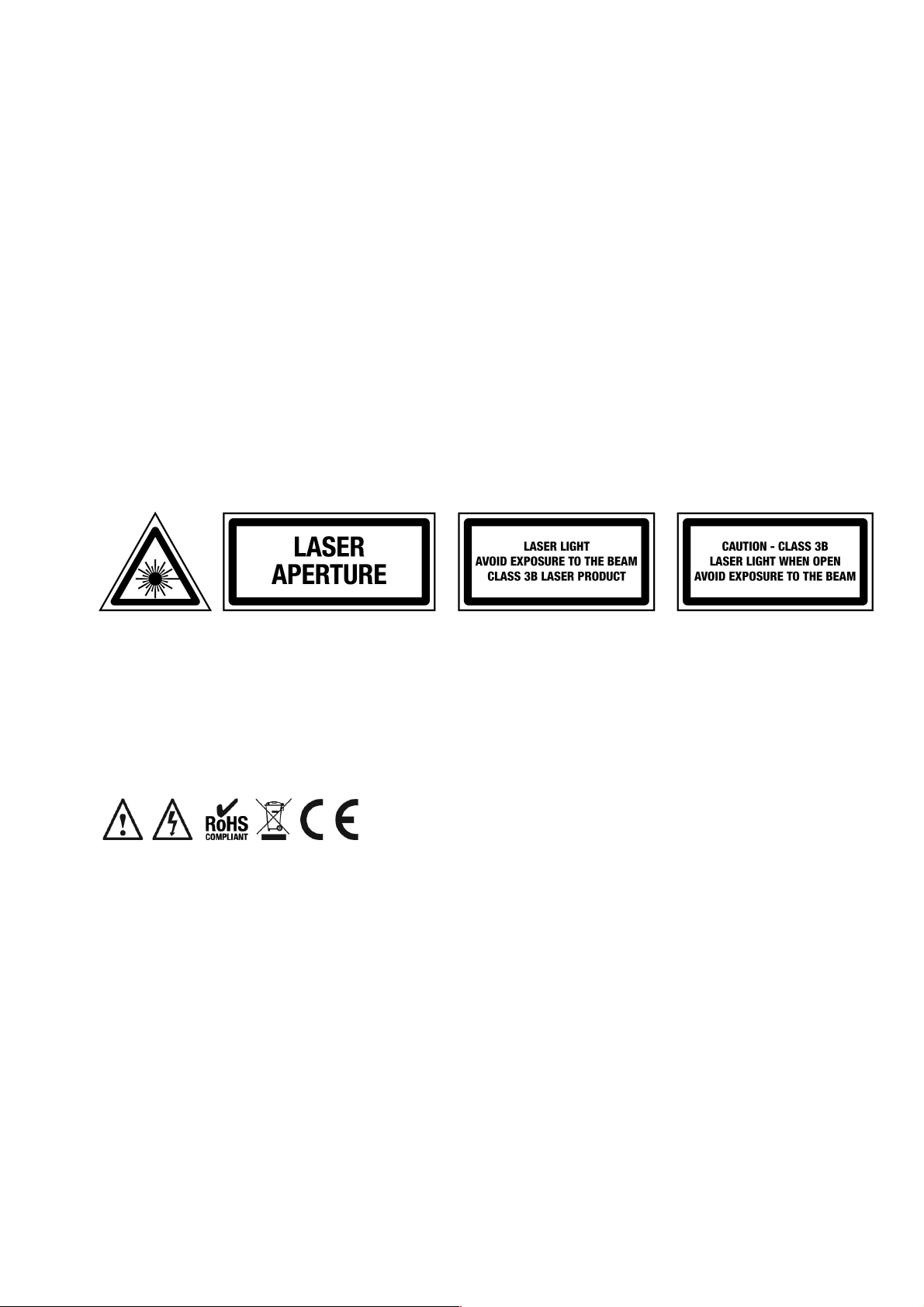
The lightning flash symbol inside a triangle is to alert the user to the presence high voltage within the unit’s enclosure that may
be of sufficient power to constitute a risk of electrical shock to persons. Caution: to prevent the risk of electric shock, do not
attempt to open the unit. No user-serviceable parts inside. Refer all servicing to qualified service personnel. The exclamation
mark inside a triangle is intended to alert the user to the presence of important operating and maintenance instructions in the
literature accompanying the appliance. Please read and pay attention to all laser safety warning sticker labels on the unit.
Select the installation location of your unit carefully. Avoid placing it in direct sunlight or locations subject to vibration and excessive dust.
Do not use the unit where there are extremes in temperature (below 41ºF / 5ºC or exceeding 95ºF / 35ºC).
Unpacking and safety Please unpack your new product carefully. Your new product should reach you in perfect condition. Please check
that no damage has occurred during transit. If any damage is found, do not operate your unit. Please contact the retailer you purchased it
from immediately. If there is any damage to the mains cable do not use the device. Always disconnect the unit from the mains supply when
carrying out any cleaning of the unit.
Manufacturer declarations
In compliance with the following requirements: RoHS Directive (2002/95/EU) and WEEE Directive (2002/96/EU).
If this product is ever no longer functional please take it to a recycling plant for environmentally friendly disposal.
CE declaration of conformity
R&TTE Directive (1999/5/EU), EMC Directive (2004/108/EU), Low Voltage Directive (2006/95/EU).
The declarations are available on application from certification@lambaplc.com
Before putting the devices into operation, please observe the respective country-specific regulations.
This manual contains important laser system safety and operation information. Read and understand all instructions prior to powering on
the laser unit the first time to avoid eye injury and to avoid breaking the law. Keep this manual in a safe place for future reference. Lasers
can be hazardous and have unique safety considerations. Permanent eye injury and blindness is possible if lasers are used incorrectly.
Pay close attention to each safety WARNING statement in this manual.
Please refer to the Kam Class 3B Laser Safety Guide (available from kam.co.uk) for more information on laser safety issues.
Page 3
Laser safety warnings…
Potential laser injury hazard exists with this product! Please read these instructions carefully, which include important information about
installation, safe use and service!
Caution Avoid direct eye contact with laser light. Never intentionally expose your eyes or others to direct laser radiation.
Caution This laser product can potentially cause instant eye injury or blindness if laser light directly strikes the eyes.
Caution It is illegal and dangerous to shine this laser into audience areas.
Caution It is illegal and dangerous to shine any laser at aircraft.
Caution Operating procedures other than those specified herein may result in hazardous radiation exposure.
Overhead rigging
Important - the installation must be carried out by qualified service personal only. Improper installation can result in serious injuries and /or
damage to property. Overhead rigging required extensive experience. Working load limits should be respected, certified installation
materials should be used, the installed unit should be inspected regularly for safety.
l Make sure the area below the installation place is free from unwanted persons during rigging, de-rigging and servicing.
l Locate the unit in a well ventilated spot, far away from any flammable materials and/or liquids. The fixture must be fixed at least 50cm
from surrounding walls
l The device should be installed out of reach of people and outside of areas where persons may walk by or be seated.
l Before rigging make sure that the installation area can hold minimum point load of 10 times the device`s weight.
l The device should be well fixed; a free swinging mounting is dangerous.
l Do not cover any ventilation opening as this may result in overheating
Before first time use, the unit should be inspected for safety. Inspection the unit regularly every year.
AC power
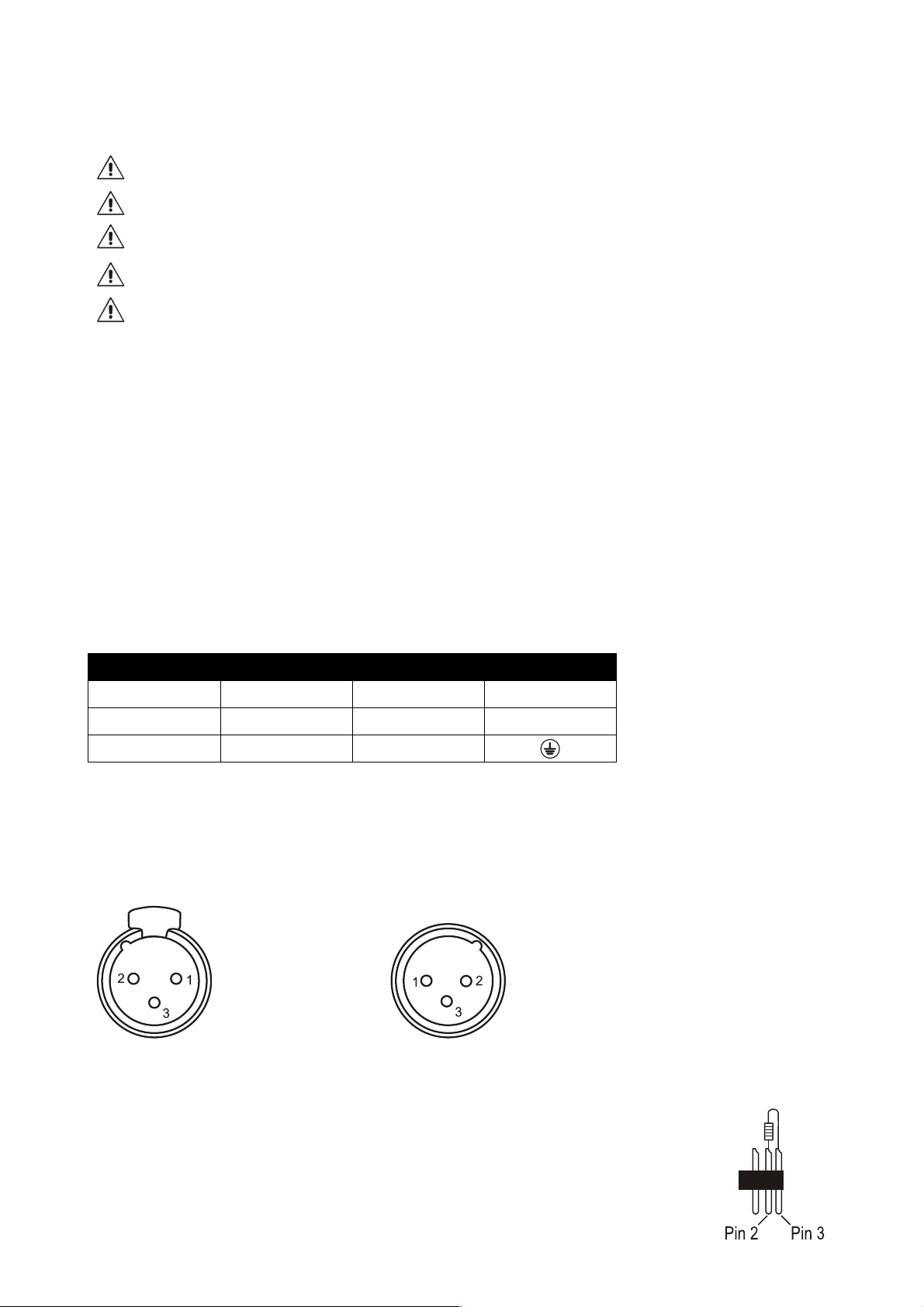
The unit is supplied with a power plug appropriate to its voltage. Should any other connections be required they must be carried out with
the following configuration:
Cable (EU)
Cable (US)
Pin
International
Brown
Black
Live
L
Light blue
White
Neutral
N
Yellow/green
Green
Earth
DMX-512 connection
If you are using a standard DMX controller, you can connect the DMX output of the controller directly to the DMX input of the first unit in a
DMX chain. If you wish to connect a DMX controller with other XLR outputs you will need to use adapter cables.
1 = shield
DMX output 2 = Signal (-) DMX input
3 = Signal (+)
Connect the DMX output of the first unit in a DMX chain with the DMX input of the next unit in the chain. Always connect the the output of
one unit with the input of the next unit until all units are connected.
If you use a controller with 5 pin DMX connection you will need to use a 5 pin to 3 pin adapter.
Caution at the unit, the DMX cable has to be terminated with a terminator. Solder a 120 Ohm resistor
between Signal (-) and Signal (+) into a 3-pin XLR connector and plug this into the DMX output of the
last unit in the chain.
Page 4
The Kam Hyper3D 500 is a spectacular laser offering 8 different effects in one package. The table below outlines the usage modes along
with a description of each effect.
Mode
Effect No.
Effect name
Menu
Auto
1
Hyper 3D
2
Wide beam grating
3
Northern lights
4
Multi-grating
5
Spirostar
6
Kaleidoscope
7
Wide-angle stars
8
Flat beam & in-air tunnel
Sound-to-Light
1
Hyper 3D
2
Wide beam grating
3
Northern lights
4
Multi-grating
5
Spirostar
6
Kaleidoscope
7
Wide-angle stars
8
Flat beam & in-air tunnel
Mode: This is either AUTO where each selected effect varies randomly or Sound-to-Light where the selected effect changes in time to the
beat of the music.
Effect No.: This is the allocated number for the specific effect.
Effect name: This is the name of the specific effect.
Menu: This is the symbol that appears on the LED display on the back of the unit.
When using this unit in DMX mode it is important to understand that this will override all internal effects and all the moving effects can be
stopped to produce single beams. For this reason it is vital to ensure that no single beams can go into audience at distances less than
those specified in the table above.
The same applies for the unit being used in ILDA mode – all the internally programmed images are overridden. Any audience scanning
must be with the fastest possible scan rate and largest possible images at distances determined by careful calculation. If in any doubt –
don’t audience scan.
Page 5

Front and rear panel controls and functions
Number
Feature
Function
1
Laser output aperture
The laser light is emitted from here. Never look directly into the hole when the unit is on.
2
Power LED
Indicates that the unit is switched on.
3
Sound indicator LED
Flashes when an audio signal is received by the built-in microphone for reference.
4
Handle bracket
Adjustable handle for carrying the unit and for mounting.
5
Safety chain eyelet
Attach safety chain to this eyelet when mounting the unit.
6
ILDA through
Standard ILDA interface. Used to connect to other ILDA lasers.
7
ILDA input
Standard ILDA interface. Automatically switches between the internal program and ILDA.
8
LED display
LED display showing operation mode.
9
Control buttons
Selects the units various functions.
10
Remote switch
Safety feature. Removal of this insert shuts down the laser diodes. Keep interlock inserted.
11
Key lock
Insert the supplied safety key before being able to turn the laser On or Off.
12
DMX input
3 pin XLR connector for DMX communication.
13
DMX output
3 pin XLR connector for DMX communication.
14
Power switch
Turns the unit on or off when connected to the mains power supply.
15
Power supply input
Attach the IEC mains cable here. Built-in fuse and spare fuse
Page 6

Operating Mode
When the laser is powered on, the LED Control Panel (8) on the rear panel shows the current operating standalone mode or the DMX
address. With help of the LED Control Panel, it is very easy to set and change the operating mode of the laser. The next time the laser is
powered on, it will show the last setting used before the unit was powered off.
LED Control Panel buttons
Funtion button (FUNC) > mode option, press button to choose the operating mode of laser.
UP and DOWN buttons > press either button to change operating mode, parameter or DMX address.
ENTER button > press button to confirm a setting.
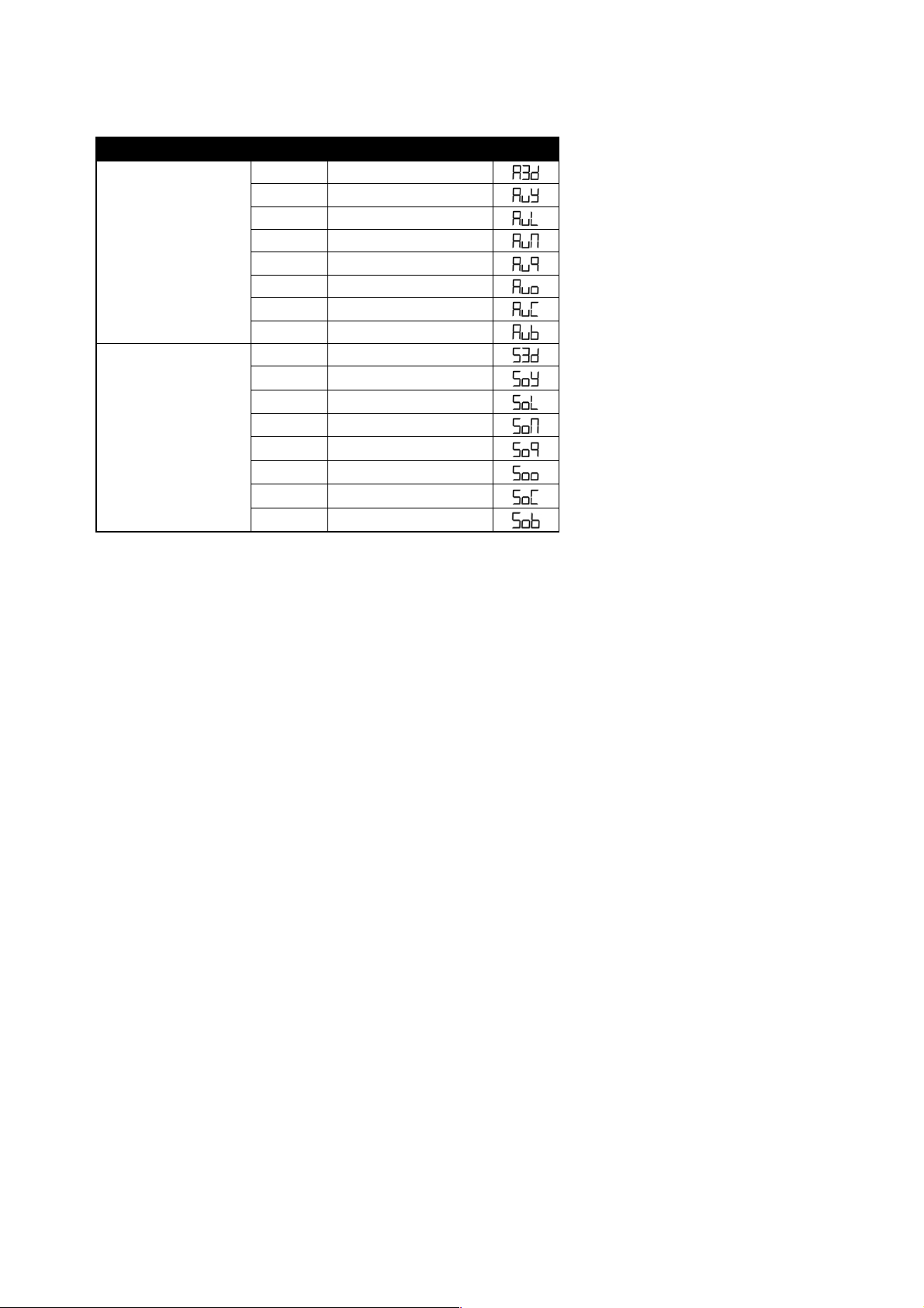
Operation
Display
Standalone mode – pre-programmed effect
AuT
Automatically cycle through its eight built in programs.
A3d
Automatically cycle through the built-in hyper 3D effects
AuY
Automatically cycle through the built-in wide beam grating effects
AuL
Automatically cycle through the built-in northern lights effects
Aun
Automatically cycle through the built-in multi-grating effects
Au9
Automatically cycle through the built-in spirostar effects
Auo
Automatically cycle through the built-in kaleidoscope effects
Page 7

Sound Activated Mode (sensitivity setting)
The laser has a built in microphone and to reduce and increase the sensitivity of the pick up,
which will alter the reaction of the programs, use the Sound activation mode settings.
• Press FUNC till you see S6
• Press UP/DOWN to set the microphone sensitivity. S 0 is no sound activation,
from S 1 to S 9; the sensitivity level will increase and be more sensitive.
• Press ENTER to confirm.
ATTENTION! In pre-programmed standalone MUSIC SHOW mode, the laser beams will blackout in 3 seconds without AUDIO/MIC
activated signal.
DMX Mode
• Press FUNC to enter the MODE selection
• The LED panel will show 001 for DMX mode
• Press ENTER to confirm the setting. Now the laser is working in DMX mode.
Use the up/down buttons to select the DMX address.
Note: In DMX MODE, once the DMX cable is connected to the laser and DMX controller,
the DMX LED in front panel of laser will be ON.
When DMX signal is present, the LED display will stop flashing.
Controlling units via DMX - each unit uses 19 DMX channels
To set the DMX address
1. Press the function button until *** is displayed (range 001-512)
2. Using the up / down buttons select the desired DMX starting address
3. Press the enter button to confirm
4. Continue this formula to address any additional units
Note on setting the DMX address of units - If one or several units are to be controlled at the same time with the same features, set all units
DMX address to the same value
Example all units to 001
If individual control of several units is required, each unit must have its on unique address and no channels must cross
Example unit 1 set to 001 – unit 2 to 020 etc adding 19 clear channels each time
AuC
Automatically cycle through the built-in star effects
AUb
Automatically cycle through the built-in flat beam & in-air tunnel effects
Sou
Sound Activated Show in corresponding effect
S3d
Cycle through the built-in hyper 3D effects by sound activation
SoY
Cycle through the built-in wide beam grating effects by sound activation
SOL
Cycle through the built-in northern lights effects by sound activation
Son
Cycle through the built-in multi-grating effects by sound activation
So9
Cycle through the built-in spirostar effects by sound activation
Soo
Cycle through the built-in kaleidoscope effects by sound activation
SoC
Cycle through the built-in star effects by sound activation
Sob
Cycle through the built-in flat beam & in-air tunnel effects by sound activation
Page 8

Slave Mode
• Press FUNC to enter the MODE selection
• The LED panel will show SLA for slave mode
• Press ENTER to confirm the setting Now the laser is working in SLAVE mode.
Master slaving units with no DMX controller
Set the master unit to the desired setting
Example: auto or sound
Set all other units to slave mode
To set slave mode press the function button until SLA is displayed then press the enter button to confirm
Only one unit must be set as a master and all other units must be set as slave
Connect each unit together via a 3pin DMX lead
Pattern Mirror Reverse Setting
• Press FUNC to enter the MODE selection
• Use the up/down buttons to set the LED display to match Fig A.
• Press ENTER to confirm the setting.
• Using the up/down buttons set the display to match Fig. B.
This will rotate the graphic in the X direction.
• Using the up/down buttons set the LED display to match Fig. C.
This will flip the graphic in the Y direction.
• Using the up/down buttons set the LED display to match Fig. D.
This will flip the graphic in the X and Y directions.
ILDA Control Mode
This unit has the ILDA DB25 port, which allows control of the laser via a PC/Mac laser or lighting software. The PC must be connected to
an interface and then the ILDA cable from the interface is connected to the ILDA input socket on the rear of the laser. When connecting the
ILDA plug to the laser this will override all built in standalone functions of the laser, and can then only be controlled by the PC/Mac
software. Removing the ILDA cable will re-enable all standalone functions.
Please note: it should be possible for any ILDA controlled software to operate this laser, if your software is having problems controlling the
laser this maybe down to a cable connection issue. Some interfaces and cables may have different wiring configuration. The fourth and
seventeenth pin of the ILDA socket need to be connected. If you rectify this issue on your interface then this will cure the control issue.
Fig A.
Fig B.
Fig C.
Fig D.
Page 9

DMX channel table
Channel
Value
Description
Channel 1
mode
000-018
Laser OFF
019-030
Mixed effect AUTO show - 8in1
031-042
AUTO grating 1 (A3D) - hyper 3D effects
043-054
AUTO grating 2 (AUY) - wide beam grating effects
055-066
AUTO grating 3 (AUL) - northern lights effects
067-078
AUTO grating 4 (AUN) - multi-grating effects
079-090
AUTO grating 5 (AUQ) - spirostar effects
091-102
AUTO grating 6 (AUO) - kaleidoscope effects
103-114
AUTO grating 7 (AUC) - star effects
115-126
AUTO scanned beam (AUB) - in-air tunnel effects
127-138
Mixed effect sound show - 8-in-1
139-150
SOUND grating 1 (A3D) - hyper 3D effects
151-162
SOUND grating 2 (SOY) - wide beam grating effects
163-174
SOUND grating 3 (SOL) - northern lights effects
175-186
SOUND grating 4 (SON) - multi-grating effects
187-198
SOUND grating 5 (SOQ) - spirostar effects
199-210
SOUND grating 6 (SOO) - kaleidoscope effects
211-222
SOUND grating 7 (SOC) - star effects
223-234
SOUND scanned beam (SOB) - in-air tunnel effects
235-244
DMX control, only star effect, see chart 1
245-255
DMX control, grating and pattern, see chart 2
DMX Chart 1 (when CH1 is at 235-244), only with Star effect
Channel
Value
Description
Channel 3
Colour
000-007
Original preprogrammed color
008-015
Red
016-023
Green
024-031
Red and green
032-039
Blue
040-047
Red and blue
048-055
Blue and green
056-063
Red, Green and Blue
064-111
Colour rolling
112-159
Colour jumping
160-207
Multi colour speed
208-255
Strobe
Page 10

Channel 4
X move
000-127
128 different fixed position on X axis
128-255
Shake effect
Channel 5
Move speed
000-255
Fast to slow of channel 4 Shake effect
Channel 6
Y move
000-127
128 different fixed position on Y axis
128-255
Shake effect
Channel 7
Move speed
000-255
Fast to slow of channel 6 Shake effect
DMX Chart 2 (when Channel 1 is at DMX address 245-255), with grating and patterns effect
Channel
Value
Function
Channel 2
Group
000-051
Pattern group 1
052-103
Pattern group 2
104-155
Pattern group 3
156-207
Pattern group 4
208-255
Pattern group 5
Channel 3
Pattern
000-255
16 patterns options in each group
Channel 4
Grating / effect
wheel
000-031
Grating effect 1 - hyper 3D effects
032-063
Grating effect 2 - wide beam grating effects
064-095
Grating effect 3 - northern lights effects
096-127
Grating effect 4 - multi-grating effects
128-159
Grating effect 5 - spirostar effects
160-191
Grating effect 6 - kaleidoscope effects
192-255
Flat beam & in-air tunnel effects
Channel 5
Grating rotating
000-004
No grating rotation
005-127
Anticlockwise rolling
128-133
No grating rotation
134-255
Clockwise rolling
Channel 6
Colour
000-007
Original preprogrammed color
008-015
Red
016-023
Green
024-031
Yellow
032-039
Blue
040-047
Pink
048-055
Cyan
056-063
White
064-111
Single colour change
112-159
Color Jumping
Page 11

160-207
Color Moving
208-255
Strobe effect
Channel 7
Clipping
000
Full pattern without clipping
001-127
0%~99% fixed pattern clipped
128-255
Clipping Speed
Channel 8
Zooming
000-127
100%-5% fixed pattern zoomed
128-169
Zooming IN
170-209
Zooming OUT
210-255
Alternately Zooming
Channel 9
Zoom speed
000-255
Fast to Slow
Channel 10
Y Axis Rolling
000-127
0 - 359 degree fixed Y axis rolled
128-191
Anticlockwise rolling
192-255
Clockwise rolling
Channel 11
Roll Speed
0-255
Fast to Slow
Channel 12
X axis Rolling
000-127
0 - 359 degree fixed X axis rolled
128-191
Rolling & morphing effect 1
192-255
Rolling & morphing effect 2
Channel 13
Roll speed
0-255
Fast to Slow
Channel 14
Z axis rolling
000-127
0 - 359 degree fixed Z axis rolled
128-191
Anticlockwise rolling
192-255
Clockwise rolling
Channel 15
Roll speed
0-255
Fast to Slow
Channel 16
X axis moving
000-127
128 different fixed position on X axis
128-191
Rolling & morphing effect 1
192-255
Rolling & morphing effect 2
Channel 17
Move speed
0-255
Fast to Slow
Channel 18
Y axis moving
000-127
128 different fixed position on Y axis
128-191
Rolling & morphing effect 1
192-255
Rolling & morphing effect 2
Channel 19
Move speed
0-255
Fast to Slow
Page 12

Pattern List
DMX
1 2 3 4 5
000-015
016-031
032-047
048-063
064-079
080-095
096-111
112-127
128-143
144-159
160-175
176-191
192-207
208-223
224-239
240-255
Specification
Mains Input
AC100~240V, 50/60Hz
Fuse / power consumption
250V /1.6A Slow Blow (20mm Glass) / 50w
Motor speed
10K@±15°
Music control
Audio / Sound activated by built-in mic
Laser power
100mW 638nm Red
80mW 532 Green
300mW 450nm Blue
Laser classification
Class 3B
Condition temperature
10~40℃
DMX connections
3 pins XLR male/female
DMX channels
19 Channel
Measurements
290 x 240 x 110mm (WxDxH)
Unit Weight
4.2kgs
 Loading...