

Page 1
KAM® E-IAS™
ELECTRIC ISOKINETIC AUTOMATIC SAMPLER
PER API 8.2, ASTM D4177
AND ISO 3171
User Manual
EIASMANUAL0719
TEL +1 713 784-0000
FAX +1 713 784-0001
Email Sales@Kam.com
KAM CONTROLS, INC.
3939 Ann Arbor Drive
Houston, Texas 77063 USA
www.KAM.com
An ISO 9001 certified company
Page 2

TABLE OF CONTENTS
SECTION TITLE PAGE
1 Introduction 2
•Available Models and Mounting Options 2
2 Specifications 3
3 Installation 4
•Installation Considerations 4
• Fixed Insertion Installation 4
• Insertable Models Installation 5
• Wiring Diagram 10
4 Maintenance 11
•Parts List 11
•Replacing Seals and O-rings 12
CAUTION:
When installing the E-IAS™ sampler in a pipeline containing petroleum products,
petro-chemicals, waste waters with the presence of pressure & temperature, and high-pressure
steam refer to the Pipeline Operators’ “Health, Safety and Environmental Policy Procedures” to
ensure safe installation.
KAM CONTROLS, INC. reserves the right to make changes to this document without notice.
EIASMANUAL 0918
1
KAM CONTROLS, INC.
Page 3
INTRODUCTION
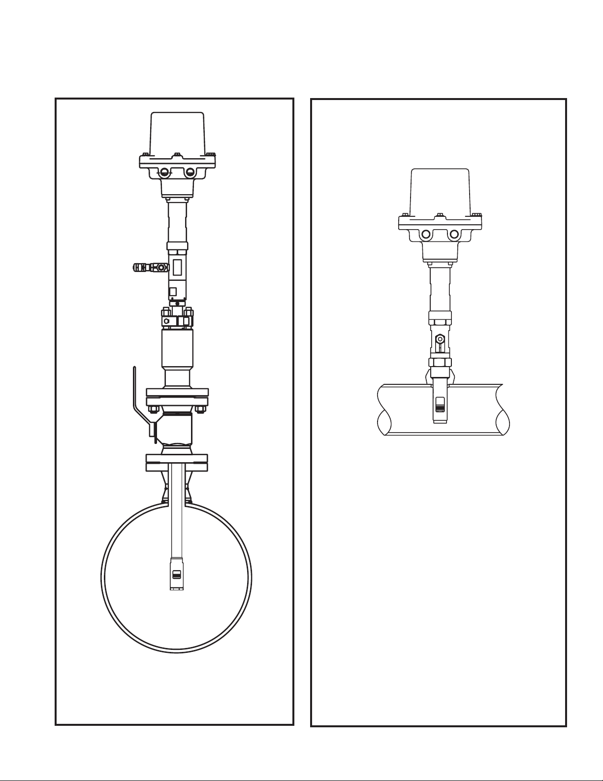
AVAILABLE MODELS and MOUNTING OPTIONS
FIG. 1-2FIG. 1-1
Full-opening
Ball Valve
Option 1: Insertable/retractable E-IAS™
with 2”, 3”, or 4” flanged seal housing or 2" MNPT
Option 2: Fixed insertion E-IAS with 1.25" NPT
or 2", 3" or 4" flange
EIASMANUAL 0918
2
KAM CONTROLS, INC.
Page 4

SPECIFICATIONS
Media: Liquid hydrocarbons, including crude oil and condensate
Materials: Wetted parts SS316, Peek
Standard O-rings Viton
Bite size: 0.5, 1, 1.5 or 2 cc
Sample rate: 20 samples/minute max
Viscosity: 1-500 cSt
Pipe size: 1 – 36”
Max pressure: 285 psi
Temperature: -40º to 350ºF (-40º to 177ºC)
Electrical
Requirements: 120 VAC 2.0A RMS
50/60 Hz single phase
-20 ºC to +45 ºC
Motor: High-torque stepper motor
EIASMANUAL 0918
3
KAM CONTROLS, INC.
Page 5
INSTALLATION
PRIOR TO INSTALLATION
Before installing the E-IAS™ Sampler, thoroughly inspect to ensure that unit was not damaged during transit.
KAM CONTROLS recommends that the E-IAS™ Sampler be installed 2 to 4 pipe diameters downstream of a
KAM® static mixer and in conjunction with a KAM® ML™ Measurement Loop. At the time of installation the
pipeline pressure needs to be reduced to under 100 psi in order to safely install the E-IAS™ Sampler.
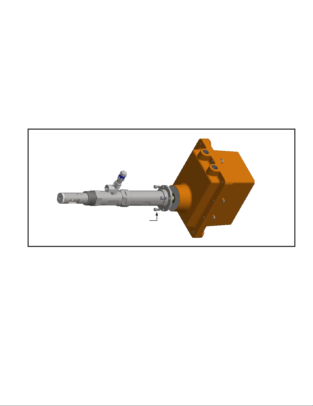
The KAM® E-IAS is shipped with the motor and housing separate from the probe body. KAM recommends full
installation of probe (including insertion on insertable models) prior to attaching motor housing to probe body. If
motor housing is attached at time of installation, detach prior to installation by removing the (4) hex screws at the
bottom of the housing with a 3/16 Allen wrench. (Fig. 3-1)
FIG. 3-1
Prior to installation,
remove hex screws with a 3/16 Allen wrench
FIXED INSERTION MODELS INSTALLATION
In horizontal lines, the E-IAS™ Sampler should be installed with the probe horizontally oriented at 3 or 9 o’clock.
KAM recommends using liquid pipe sealant rather than Teflon tape on all threaded connections.
Insertion distance/shaft length is set at factory. After installation of probe body on the line, attach the motor housing
to probe body using four hex screws and a 3/16 Allen wrench. (Fig. 3-1).
Follow wiring instructions on page 10 of this manual.
EIASMANUAL 0918
4
KAM CONTROLS, INC.
Page 6
INSTALLATION
INSERTABLE/RETRACTABLE MODELS INSTALLATION
In horizontal lines, the E-IAS™ Sampler should be installed with the probe horizontally oriented at 3 or 9 o’clock.
Fig. 3-2.
The E-IAS™ Sampler Probe should be inserted so that the middle of the sampling window is in the 20% center area
of the pipe. Fig. 3-2. It is the user’s responsibility to ensure that the E-IAS™ Sampler is placed in the most representative point in the flow profile.
Insertable models of the E-IAS™ Sampler should be installed according to Fig. 3-2. The Full-Opening Ball Valve is
used to isolate the E-IAS™ Sampler from the pipeline during installation or removal. The Seal Housing of the E-IAS™
Sampler allows the Sampler Probe to be inserted in and out of the pipe under pressure and flow conditions up to 100
psi.
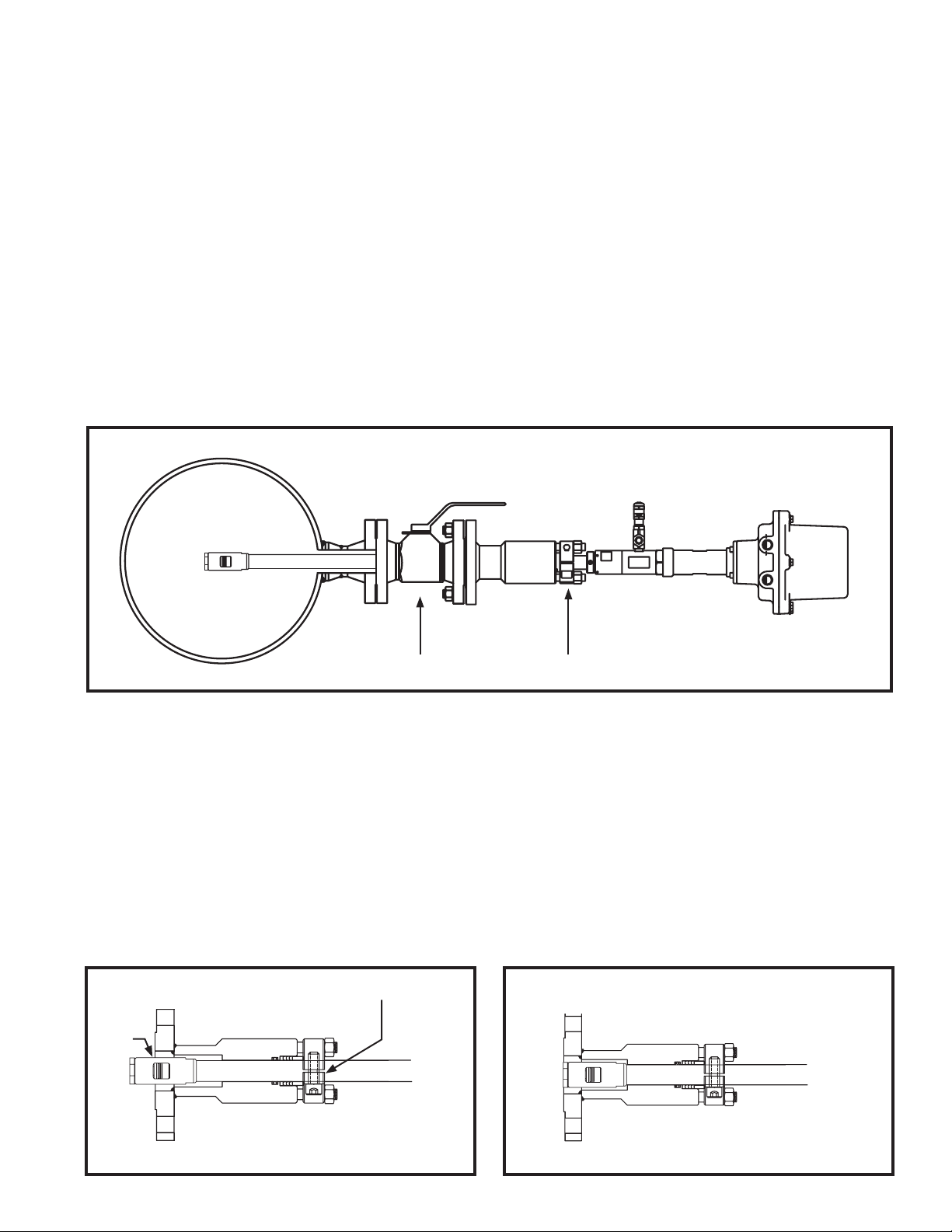
FIG. 3-2
Full-opening
Ball Valve
Hex socket cap screws
Before mounting the E-IAS™ Sampler on the Full-Opening Ball Valve, determine the insertion length required.
1.
Lay the E-IAS™ Sampler on the ground or a table.
Loosen Hex Socket Cap Screws on the Locking Collar using a 3/8" Allen wrench. Fig. 3-2. This will allow the E-
2.
IAS™ Sampler Shaft to slide through the Seal Housing.
3.
Push the E-IAS™ Sampler Shaft though the Seal Housing until the middle of the sampler window chamber is
aligned with the end of the Seal Housing. Fig. 3-3.
4.
Use a Sharpie or other permanent marker to mark the shaft at the edge of the Locking Collar. (Do not use anything sharp to mark the shaft. This will create grooves that will damage the O-rings in the Seal Housing.)
FIG. 3-3 FIG. 3-4
Align
here
Mark Here
EIASMANUAL 0918
5
KAM CONTROLS, INC.
Page 7

INSTALLATION CONTINUED
Pull Shaft back until the Probe is all the way within the Seal Housing and tighten the Hex Socket Cap Screws on
5.
the Locking Collar. This will prevent the E-IAS™ Sampler Shaft from sliding and the Probe will be protected inside
the Seal Housing until and during installation. Fig. 3-4.
6.
Measure the distance (D1) from the top of the main pipe to the end of the connection where the E-IAS™ Sampler
is going to be installed. Fig. 3-5.
FIG. 3-5
D1 D1
Calculate the insertion distance using the following formula:
7.
TID – Total Insertion Distance
D1 – Distance from the top of the valve to the pipe
WT – Pipe Wall Thickness
TD – Threaded Depth
ID – Inside Diameter
For Flanged Seal Housing
Total Insertion Distance (TID)= D1 + WT + (Pipe ID x 7/16) + Seal Thickness
Example: D1= 14"
WT= .25"
ID = 8.125"
Seal Thickness=1/8"
TID=14 + .25 + (8.125 x 7/16) + 1/8
14 + .25 + 3.55 + .125=17.93
EIASMANUAL 0918
6
KAM CONTROLS, INC.
Page 8

INSTALLATION CONTINUED
For 2" MNPT Seal Housing
TID cannot be calculated until the Seal Housing is screwed into place. Bolt or Screw the E-IAS™ Sampler to the
Valve or designated installation location. (KAM CONTROLS recommends liquid thread sealant and not teflon tape
for the threaded E-IAS™ Sampler.)
You must then measure the Threaded Depth (TD) into the Valve or connection in order to calculate TID. You can do
this by measuring the distance from the edge of the Valve or female connection to the top of the Seal Housing
body and subtracting that distance from 5.25". Fig 3-6.
FIG. 3-6
Threaded Depth
Measuring Points
Total Insertion Distance (TID)= D1 + WT + 7/16 Pipe ID -Threaded Depth (TD)
For example: If the measured distance from the top of the Valve and the top of the Seal Housing body is 4.65"
you should calculate the threaded depth (TD) by subtracting 4.65" from 5.25". (5.25-4.65=0.6)
8.
You are now ready to calculate the TID.
TID= D1 + WT + (Pipe ID x 7/16) - TD (from page 8)
Example: D1= 14"
WT= .25"
ID = 8.125"
TD=.6"
TID=14 + .25 + 3.55 - .6=17.2
EIASMANUAL 0918
7
KAM CONTROLS, INC.
Page 9

INSTALLATION CONTINUED
9.
For all insertable models, use the calculated TID and make another mark on the shaft, measuring from
First Mark. Fig 3-7.
FIG. 3-7
TID
First Mark Second Mark
If you have an E-IAS™ Sampler with a Flanged Seal Housing, you may now attach it to the Valve on the pipeline.
10.
Slowly open Full Opening Valve and check for leaks.
11.
Loosen Hex Socket Cap Screw on the Locking Collar.
12.
13.
Align Window of the E-IAS™ Sampler to face the flowing stream. This can be done by aligning the Flow
Indicators in parallel with the main pipe. The Flow Indicators are located at the bottom of the Actuator
Housing.
Push the E-IAS™ Sampler in until the Second Mark is at the top edge of the Locking Collar. Fig. 3-8.
14.
FIG. 3-8
Second Mark
EIASMANUAL 0918
8
KAM CONTROLS, INC.
Page 10

INSTALLATION CONTINUED
Re-tighten the Hex Socket Cap Screw.
15.
16.
Tighten the Hex Nuts holding the Locking Collar from ¼ to ½ of a turn. The Hex Nuts holding down the Locking
Collar should never be over tightened. Their major function is to apply light pressure on the Chevron Packing to
ensure a secondary seal between the Seal Housing Body and the Insertion Shaft. Fig. 3-9.
FIG. 3-9
PRV
Locking Collar
Hex Nuts
Hex Socket Cap Screw
The PRV arrives set at the maximum cracking pressure for the spring installed (normally a yellow spring for 750
1 7.
psi). If the maximum pressure does not exceed 350 psi, set the cracking pressure to the lowest cracking pressure for the PRV by twisting the cap 8 turns counter-clockwise. The PRV is going to have the highest
cracking pressure when the cap is screwed all the way in and the lowest cracking pressure when the cap is
almost all the way out. If your line pressure is within the range of the cracking pressure of the PRV, take the following steps to set the correct cracking pressure:
a) Slowly turn the cap counter-clockwise until liquid starts to come out of the PRV outlet.
b) Turn the cap two turns clockwise to stop the leak and set the PRV cracking pressure 200psi above the
current pressure.
c) Tighten lock nut against the cap.
d) Lock wire cap and body together to maintain set pressure.
EIASMANUAL 0918
9
KAM CONTROLS, INC.
Page 11

INSTALLATION CONTINUED
*
Th
Th
unles
begining of the previous pulse
WIRING DIAGRAM
FIG. 3-10
Supply Voltage
94-135VAC 3Amps
6A fast acting fuse
recomended.
Sampler
Controller
or
PLC
NOTE: the pulse duration should be between
The pulse duration should be between 200 ms and 1000ms.
200 ms and 1000 ms. The minimum time between
e minum time between pulses is 3 seconds.
e E-IAS will start the actuation to take a sample with every pulse
pulses is 3 seconds.
s it receivea a pulse before 3 seconds have passed from the
L
N
GND
GND
+ 5-24V DC Pulse *
L
N
GND
D2 (-)
D2 (+)
D1 (-)
D1 (+)
EIASMANUAL 0918
10
KAM CONTROLS, INC.
Page 12

MAINTENANCE
1
2
REVISION HISTORY
REV DESCRIPTION DATE
A
New Drawing
During normal operation of the KAM® E-IAS™ Sampler, some seals will wear. In order to ensure continuous
accurate sampling, KAM CONTROLS recommends replacing the seals on your E-IAS™ Sampler every six months.
A complete kit with all the E-IAS™ Sampler O-rings, seals, etc. can be ordered by contacting KAM CONTROLS at
sales@kam.com and requesting Seal Kit 361300 or by calling +1 713-784-0000 or faxing your request to
+1 713-784-0001.
FIG. 4-1 KAM® E-IAS™ SEAL KIT PART NUMBER 361300
1
3
5
9
8
4
7
6
ITEM QTY PART NUMBER DESCRIPTION
1 1 361150 Seal Bushing Assembly #1(2 internal O-rings)
2 1 361192 Seal Bushing Assembly #2 (3 internal O-rings)
3 1 360411 3/4" Plunger Piston Seal
4 1 360425 Check Spring
5 1 360390 Suction Spring
6 2 150022 2-022 O-ring 75 Durometer
7 1 150026 2-026 O-ring 75 Durometer
8 1 150013 2-013 Viton O-ring 75 Durometer
9 1 150004 2-004 Viton O-ring 75 Durometer
6
2
EIASMANUAL 0918
11
KAM CONTROLS, INC.
Page 13

MAINTENANCE CONTINUED
REPLACING SEALS AND O-RINGS
The seal/O-ring replacement process requires the following
materials:
FIG. 4-3
• 3/16" Allen wrench
• 9/16", 11/16", 1 1/2", 1 3/4" wrenches, or (2) adjustable
wrenches. Do not use pipe wrenches on the E-IAS.
• Pick or hook to removed old O-rings
• Solvent/part washer
• Grease for O-ring lubrication
• Loctite 242
Prior to removing the probe from the pipeline,
1.
disconnect the probe body from the motor assembly.
Socket
Cap Screws
Using a 3/16" Allen wrench, remove the (4) socket cap
screws connecting the probe to the motor assembly.
(Fig. 4-3.) Pull the probe free of the motor assembly.
2.
Remove the E-IAS™ probe body from the pipeline.
Once you’ve removed your E-IAS™ Sampler from the
3.
Probe
Body
pipeline, clean all surfaces as much as possible.
Remove the sampling section of the probe by placing a 1-1/2" wrench on the wrench Flats of the sample chamber
4.
and turning the bottom section of the probe counterclockwise using a 1-3/4" wrench on the 1-3/4" hex section
of the probe. (Fig. 4-4)
Motor
Assy.
FIG. 4-4
Sampling Section
1 3/4" Hex
Sample Chamber Wrench Flat
EIASMANUAL 0918
12
KAM CONTROLS, INC.
Page 14

MAINTENANCE CONTINUED
Hold the sample shaft using a 9/16" wrench, while unscrewing the sample piston using an 11/16" wrench. Be
5.
careful not to lose the small check valve and spring located inside the sample piston. They are not fixed in place.
FIG. 4-5
Sample Piston
9/16" Wrench Flat
Spring and Check Valve
11/16" Wrench Flat
6.
Using a 1 1/2" wrench, remove the Sample Chamber by turning it counterclockwise while holding the Linear
Actuator with a 1 3/4" wrench. (Fig. 4-6)
NOTE: There are (2) Seal Bushing Assemblies in either end of the Sample Chamber. These may come loose or
stick to the shaft when Sample Chamber is removed.
FIG. 4-6
Linear Actuator
Sample Chamber
1 1/2" Wrench Flat
7.
Remove Seal Bushing Assemblies from both sides of the Sample Chamber using a small hook or pick. (Fig. 4-7)
Remove internal 2-022 O-rings inside both sides of the sample chamber.
8.
Clean Chamber with a solvent to remove any oil.
9.
FIG. 4-7
Seal Bushing Assemblies
1 3/4" Wrench Flat
2-022 O-rings
EIASMANUAL 0918
13
KAM CONTROLS, INC.
Page 15

MAINTENANCE CONTINUED
10.
Install new 2-022 O-rings inside both sides of the Sample Chamber.
Apply a small amount of grease around the inside of the installed 2-022 O-rings.
11.
12.
Install new Seal Bushing Assemblies inside both sides of the Sample Chamber.
Apply grease around the inside of the new Seal Bushing Assemblies.
13.
14.
Insert the Linear Actuator back through the Sample Chamber. (Fig. 4-8) The fit should be tight and may require
some force. Ensure that both Seal Bushing Assemblies are in place inside the Sample Chamber when done.
15.
Apply Loctite 242 to the threads and tighten in place using 1 1/2" wrench and 1 3/4" wrench.
FIG. 4-8
1 3/4" Wrench Flat
1 1/2" Wrench Flat
Loctite 242
16.
Replace 2-013 O-ring from the sample shaft. (Fig. 4-9)
Replace 2-004 O-ring on the sample check valve.
1 7.
18.
Replace spring if necessary.
19.
Insert check and spring back into the sample piston.
Clean the sample shaft threads.
20.
21.
Screw the sample piston on to the sample shaft by holding the shaft with a 9/16" wrench and using an 11/16"
wrench to turn the sample piston.
FIG. 4-9
EIASMANUAL 0918
2004 O-ring
Spring
14
2013 O-ring
Sample Shaft Threads
KAM CONTROLS, INC.
Page 16

MAINTENANCE CONTINUED
22.
On the remaining sampling section, remove the Bottom Seal Holder by using a 1 1/8" wrench. (Fig. 4-10)
FIG. 4-10
Bottom Seal Holder
1 1/8" Wrench Flat
23.
Using a 5/32" Allen wrench remove the Cover holding the plunger seal. (Fig. 4-11)
24.
Inspect the Spring and Check Valve for damage and
replace if necessary.
25.
Using solvent clean the inside threads of the Cover.
26.
Place Check Valve and Spring back in place.
Install a new Plunger Seal.
2 7.
28.
Clean the outside Cover threads and apply a small
amount of blue Loctite 242 or equivalent.
FIG. 4-11
Cover
Plunger Seal
Spring and
Check Valve
29.
Screw the cover back in place using 5/32" Allen
wrench
NOTE: Do not alter small set screw on flat of Bottom Seal Holder threads. This determines sample
bite volume. To change, please consult factory.
Bottom
Seal Holder
EIASMANUAL 0918
15
KAM CONTROLS, INC.
Page 17

MAINTENANCE CONTINUED
30.
Replace the 2-026 O-ring located inside sampling section of the probe, at the same level as the hex section.
(Fig. 4-12)
Apply grease to the 2-026 O-ring previously installed.
31.
32.
Apply Loctite 242 to the Sample Chamber thread.
33.
Screw the sampling section back on to the sample chamber by holding the sample chamber with 1 1/2" wrench
and turning the bottom section of the probe clockwise using a 1 3/4" wrench.
FIG. 4-12
2-026 O-ring
Sample
Chamber
34. Install probe body on pipeline and then attach the motor assembly using a 3/16" Allen wrench and the (4) 1/4" x
1/2" socket cap screws. (Fig. 4-13)
FIG. 4-13
Socket Cap
Screws
EIASMANUAL 0918
16
KAM CONTROLS, INC.
 Loading...