

INSTALLER USER
&
MANUAL
For
Denia 14 - 14D & Mia 16 - 16D

29
GB
Dear Customer,
We thank you for having chosen one of our products, the fruit of technological experience and of continual research for
a superior quality product in terms of safety, dependability, and service.
In this manual you will nd all the information and useful suggestions to use your product with the maximum safety
and efciency.
• Incorrect installation, incorrectly performed maintenance, improper use of the product release the manufacturer from
every eventual damage derived from the use of the stove.
• The unit cannot be used as an incinerator. Do not use fuels other than pellets.
• This manual has been realized by the manufacturer and constitutes an integral part of the product and must remain
with it during its entire lifetime. If the product is sold or transferred, be sure that the booklet is present since the
information contained in it are addressed to the buyer, and to all those persons of various titles who complete the
installation, use and maintenance.
• Carefully read the instructions and the technical information contained in this manual, before proceeding with the
installation, use, and any operation on the product.
• The observance of the indications contained in the present manual guarantees the safety of people and the product,
the economy of use and a longer functioning lifetime.
• Although the carefully studied design and the risk analysis done by our company has permitted the realization of a
safe product, in any case, before effecting any operation on the stove, it is recommended to keep said manual available and pay scrupulous attention to the instructions written therein.
• Be very careful when moving the ceramic details where present.
• Check the precise atness of the pavement where the product will be installed
• The wall where the product will be placed must not be constructed in wood, or in any case, made of an inammable
material, and in addition it is necessary to maintain a safety distance.
• While the stove is in operation, several parts of the stove (door, handle, sides) can reach high temperatures. Therefore pay attention and use the proper precautions, above all in the presence of children, elderly or disabled persons,
and animals.
• Assembly must be performed by authorized persons (Authorized Assistance Center).
• Diagrams and drawings are furnished for the purpose of illustration; the manufacturer, with the intent of pursuing a
policy of constant development and renewal of the product can, without any notice, make any modications that
are believed opportune.
• When the stove is working at its maximum speed, it is strongly suggested to wear gloves while handling with the
door for pellets loading and the door handle.
• It is prohibited to install in bedrooms or in explosive environments.
• Only use replacement parts recommended by the supplier.
In the event of a fire, disconnect the power supply, use an extinguisher and call the fire fighters if necessary.
After that contact the Authorized Assistance Center.
Never cover the body of the stove in any way or obstruct the openings placed on the upper side
when the device is operating. All our stoves are trial lighted on the construction line.
This instruction booklet is an integral part of the product: make sure that it always accompanies the appliance, even in
case of transfer to another owner or in the case of transfer to another place. In the event of damage or loss, request a
copy from the area technician.
These symbols indicate specific messages in this booklet:
ATTENTION:
This warning sign indicates that the message to which it refers should be carefully read and understood,
because failure to comply with what these notices say can cause serious damage to the stove and
put the user’s safety at risk.
INFORMATION:
This symbol is used to highlight information which is important for proper stove operation. Failure to
comply with these provision will compromise use of the stove and its operation will not be satisfactory.
eniaD tovesS 6D16-ia14D_M14-1
Cod. 001122
We highly recommend to turn to our Authorized Service Centre for the installation and the first
ignition of the device as it not only carries out the installation perfectly but also verifies the
regular operation of it.
30
GB
Our company declares that the stove conforms to the
following norms for the EC European Directive labelling:
• 2014/30 UE (regulation EMCD) and following
amendments;
• 2014/35 UE (Low Voltage Directive) and following
amendments;
• 2011/65 EU (RoHS 2 directive);
• The New Rules of Construction Products (CPRConstruction Products Regulation) No. 305/2011
regarding the construction world;
• For installations in Italy, please refer to UNI 10683/98
or following changes. For the water-thermo-sanitary
equipment, let the installer give you the conformity
declaration in compliance with L. 37/2008. While
installing the unit respect the local, national and Europen
rules;
• EN 55014-1; EN 55014-2; EN 61000-3-2; EN 61000-3-3;
EN 60335-1; EN 60335-2-102; EN 62233, EN 50581.
Safety information
Please carefully read this use and maintenance manual
before installing and operating the stove!
If clarication is needed, please contact the dealer or the
Authorized Assistance Center.
• The pellet stove must only be operated in living
environments. This stove, being controlled by an
electronic board, permits a completely automatic and
controlled combustion; the exchange, in fact, regulates
the lighting phase, 5 power levels and the shut down
stage, guaranteeing the safe operation of the stove.
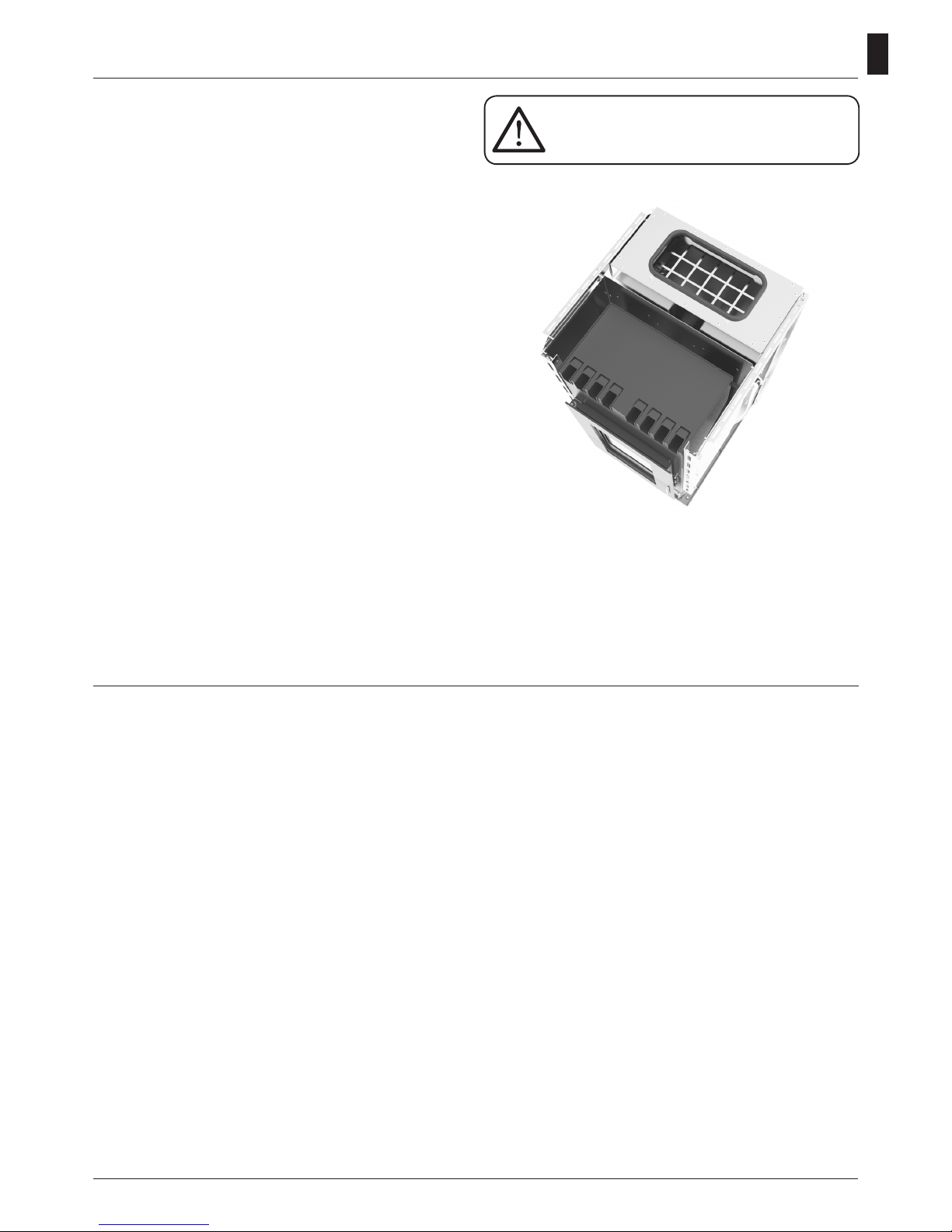
• The basket used for combustion allows most of the ash
produced by the combustion of the pellets to fall into
the collection compartment. Nevertheless, check the
basket daily, given that not all pellets have high quality
standards (use only quality pellets recommended by the
manufacturer).
Responsibility
With the delivery of the present manual, we decline all
responsibility, both civil and penal, for accidents deriving
from the partial or total lack of observance of the
instructions contained herein.
We decline every responsibility derived from improper
use of the stove, from incorrect use by the user, from
unauthorized modications and/or repairs, from the use
of replacement parts that are not original for this model.
The manufacturer declines every civil or penal, direct or
indirect responsibility due to:
• Lack of maintenance;
• Failure to observe the instructions contained in the
manual;
• Use in non-conformity with the safety directives;
• Installation in non-conformity with the norms in force in
the country;
• Installation by unqualied or untrained personnel;
• Modications and repairs not authorized by the manu-
facturer;
• Use of non-original replacement parts;
• Exceptional events.
Norms and declarations of conformity
• Use only wood pellets;
• Keep / store the pellets in a cool
dry place;
• Never pour pellets directly on the hearth;
• The stove must be fueled only with quality
pellets with a diameter of 6 mm and a maximum
length of 30 mm of the type recommended by
the manufacturer.
• Before making the electrical connection of the
stove the discharge tubes must be connected
with the flue;
• The protective grill placed inside the pellet
container must never be removed;
• The environment where the stove is installed
must have a sufficient exchange of air;
• It is forbidden to operate the stove with the
door open or the glass broken;
• Do not use the stove as an incinerator; the stove
should be used only for the intended purpose;
• Any other use is considered improper and
therefore dangerous. Do not put in the hopper
other than wood pellets;
• When the stove is operating, the surfaces,
glass, handle and tubes become very hot:
during operation do not touch these parts
without adequate protection;
• Keep the fuel and other inflammable materials
off the stove.
31
GB
Charge pellet
Fuel is loaded from the upper part of the stove by opening
a door.
Pour the pellets in the hopper; vacuum contains about 23
kg of pellets. This is easier if performed in two steps:
• Pour half of the contents of the bag into the hopper and
wait for the fuel to settle on the bottom.
• Then pour in the second half;
• Keep the cover closed , after loading the pellets , the lid
of the fuel tank;
• Before closing the door load-pellet make sure that there
are no residues of pellets around the seal. If carefully
cleaned to avoid compromising the seals.
The stove is a product by heating, presents the external
surfaces particularly hot. For this reason, we recommend
extreme caution when operating in particular:
• Do not touch the stove body and the various components, do not approach the door , it could cause burns;
• Do not touch the exhaust fumes;
• Do not perform any type of cleaning;
• Do not dump the ashes;
• Do not open the ash tray;
• Be careful that children do not come near;
• The appliance is not intended for use by persons
(including children) with reduced physical, sensory or
mental capacities , or lack of experience or knowledge,
unless they have been given through the intermediary
of a person responsible for their safety, supervision or
instruction concerning use of the appliance;
• Do not use the stove as a ladder or scaffold;
• Do not put clothes to dry on the stove. Any clothes
hangers and suchlike must be kept a suitable distance
from the stove. - Risk of re
• Carefully explain that the stove is made from material
subjected to high temperatures for the elderly , the
disabled, and in particular for all children, keeping them
away from the stove during operation
• Do not touch the stove with wet hands: the stove has
electrical components that could produce sparks if
handled incorrectly.
• Never open the glass door of the pellet stove while the
stove is in operation.
• The stove must be connected to an electrical system
equipped with an earthing conductor in accordance with
regulations 73/23 and 93/98 EEC;
• The system must be of adequate electrical power
declared the stove;
• Do not wash the inside of the stove with water.
The water could damage the electrical insulation, causing
electric shock;
• Do not expose your body to hot air for a long time. Do
not overheat the room you are in and where the stove is
installed.
This can damage the physical conditions and cause
health problems;
• Do not expose to direct the ow of hot air plants or
animals;
• The pellet stove is not a cooking element;
• External surfaces during operation can become very
hot. Do not touch them except with the appropriate
protection.
Instructions for safe and efficient use
Never remove the protection grille in the
hopper. When filling, do not let the sack
of pellets touch any hot surfaces.
32
GB
For proper functioning and a good temperature distribution,
the stove shoul be positioned in a location where it is able
to take in the air necessary for combustion of the pellet
(about 40 m3/h must be available, as laid down in the
standard governing the installation and in accordance with
local national standards).
The volume of the room must not be less than 30 m3.
The air must come in through permanent openings made
in walls (in proximity to the stove) which give onto the
outside, with a minimum cross-section area of 100 cm2.
These openings must be made in such a way that it is not
possible for then to be obstructed in any way. Alternatively,
the air can be taken from rooms adjacent to the one which
needs ventilating, as long as they are provided with an air
intake from the outside, and are not used as bedrooms or
bathrooms, and provided there is no re risk such as there
is for example in garages, woodsheds, and storerooms,
with particular reference to what is laid down in current
standards.
It is not permissible to install the stove in
bedrooms, bathrooms, or in a room where
another heating appliance is installed
(fireplace, stove etc.) which does not have its own
independent air intake.
Locating the stove in a room with an explosive
atmosphere is prohibited.
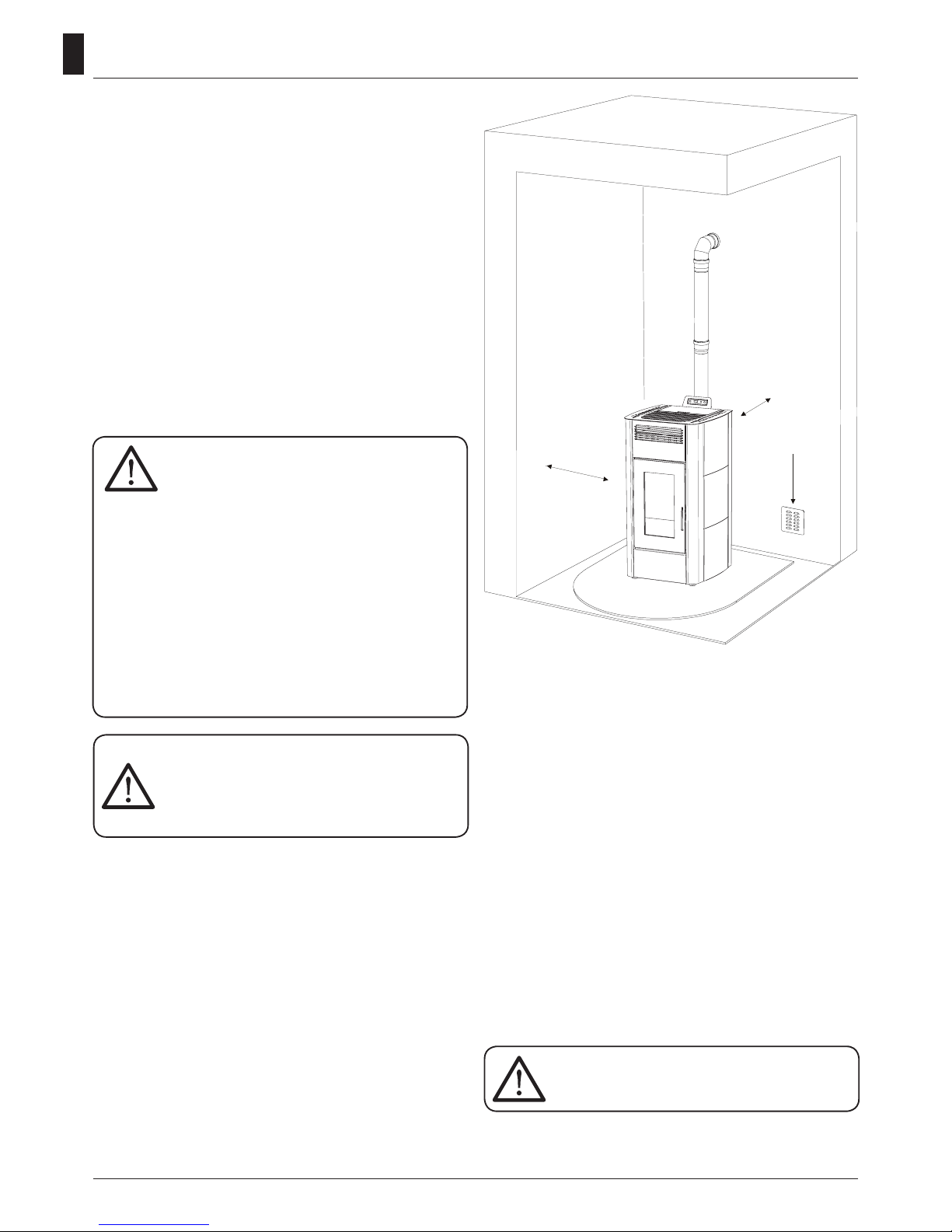
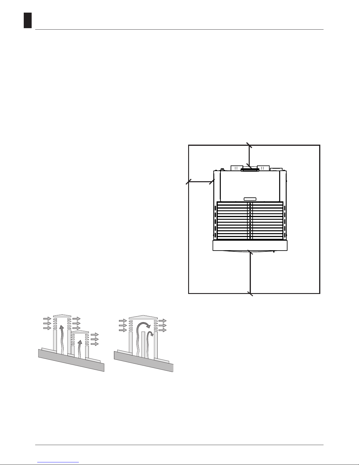
The floor of the room where the stove is to be
installed must be strong enough to take its weight. If
walls are flammable, maintain a minimum distance
of 20 cm at the rear (A), of 30 cm at the side (B) and
100 cm at the front. If the room contains objects
which are believed to be particularly delicate, such
as drapes, sofas and other furniture, their distance
from the stove should be considerably increased.
In the presence of wood floors, install a
floor protection surface in compliance
with the rules in force in the country
Operating area
30 cm
(B)
Min.
100 cm
2
20 cm (A)
Connection to the external air intake
It is essential that at least as much air must be able to ow
into the room where the stove is installed as is required for
proper combustion in the appliance and for the ventilation
of the room. This can be effected by means of permanent
openings in the walls of the room to be ventilated, which
give onto the outside, or by single or collective ventilation
ducts.
For this purpose, on the external wall near the stove, a
hole must be made with a minimum free cross-section of
100 cm2. (equivalent to a round hole of 10 cm diameter or
a square hole 10x10 cm) protected by a grille on the inside
and the outside.
The air intake must also:
•
communicate directly with the room where the stove is
installed
•
be protected by a grille, metal mesh or suitable guard, as
long as this does not reduce the area below the minimum.
•
positioned in such a way as to be impossible to obstruct.
If the stove is installed on a flammable
floor it must be interposed with a slab of
insulating material to heat it protrudes at
least 20 cm on the sides and 40 cm on the
front.
33
GB
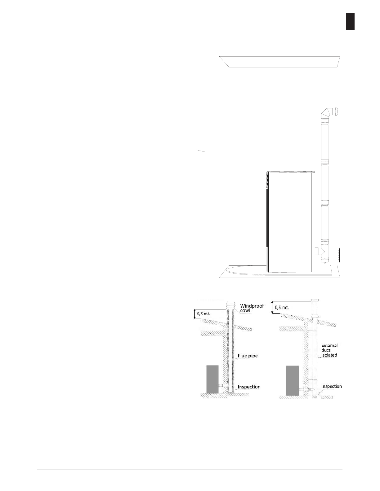
Connection to the flue pipe
The ue pipe must have internal dimensions not larger
than 20x20 cm, or diameter 20 cm. In the event of larger
dimensions, or of the ue pipe being in poor condition ( for
example cracks, poor insulation, etc.), it is advisable to t
a stainless steel pipe of suitable diameter inside the ue
pipe throughout its length, right up to the top.
Check with suitable instruments that there is a draught
between 3 Pa and 10 Pa. This type of connection ensures
the evacuation of the fumes even in the event of a
temporary power cut.
At the bottom of the ue pipe, provide an inspection cap
to allow periodic checking and cleaning, which must be
done annually. Make a gas-tight connection to the ue
pipe, using pipes and connectors as recommended by us.
You must ensure that a windproof cowl should be tted
which complies with the standards in force
Connection to an external flue with insulated or
double-wall pipe
The only type of pipe which is permissible is insulated
(double-walled) stainless steel, smooth on the inside,
xed to the wall. Flexible stainless steel pipe must not be
used. At the bottom of the ue pipe, provide an inspection
cap to allow periodic checking and cleaning, which must
be done annually. Make a gas-tight connection to the ue
pipe, using pipes and connectors as recommended by us.
You must ensure that a windproof cowl should be tted
which complies with the standards in force.
Check with suitable instruments that there is a draught
between 3 Pa and 10 Pa.
Connection to the flue pipe
For proper functioning, the connecting pipe between the
stove and the chimney or ue duct must have a slope of
not less than 3% in the horizontal stretches, the length of
which must not exceed 2 metres and the vertical distance
between one tee connector and another (change of
direction) must not be less than 1,5 m.
Check with suitable instruments that there is a draught
between 3 Pa and 10 Pa. At the botton of the ue pipe,
provide an inspection cap to allow periodic checking and
cleaning, which must be done annually.
Make a gas-tight connection to the ue pipe, using pipes
and connectors as recommended by us. You must ensure
that a windproof cowl should be tted which complies
with the standards in force.
Fig. 3: connection to an
external ue with insulated
or double-wall pipe.
Fig. 2: connection to the
ue pipe.
34
GB
Fireplace flue gas
Avoid contact with combustible materials (example:
wooden beams) and in any case provide for their insulation
with ame retardant material. In case of pipe penetrations
through roofs or walls is recommended to use special
kits crossing, certicates, are available commercially. In
the event of a chimney re, turn off the stove, disconnect
from the network and never open the door. Then call the
authorities.
The chimney cap
The chimney cap must respect the following requirements:
• It must have the equivalent diameter and internal form
of the ue.
• It must have a useful outlet diameter of not less than
double that of the ue.
• The chimney cap on the roof or that remains in contact
with the outside (for example, in case of open lofts or attics), must be covered with elements in brick or tile and
must, in any case, be well insulated.
• It must be constructed to prevent rain, snow, and extraneous bodies from entering the ue and so that the
discharge of the products of combustion is not inhibited
by wind from any quarter or strength (wind-proof chimney cap).
• The chimney cap must be positioned in such a way as
to guarantee the adequate dispersion and dilution of the
products of combustion and in any case, must be out of
the reux zone. This zone has different dimensions and
forms according to the angle of inclination of the roof so
it is necessary to adopt minimum heights (Fig. 2).
• The chimney cap must be a wind-proof type and must
be above the ridge.
• Eventual structures or other obstacles that are higher
than the chimney cap must not be too close to the
chimney cap itself.
• The device should not be installed in the ue shared.
Fig. 5: Characteristics of chimney
YES NO
REMARKS:
- the appliance must be installed by a qualied technician in
possession of the technical and professional requirements
according to the DM37/2008 that, under its responsibility,
to ensure compliance with the rules of good technique.
- you need to keep in mind all laws and national, regional,
provincial and municipal laws of the country in which you
installed the device
- check that the oor is not ammable: if necessary use a
suitable platform
- in the room where the generator must be installed to
heat must not pre-exist or be installed with an extractor
hood or ventilation ducts of the collective type.
Should these devices be located in adjacent rooms
communicating with the installation, and ‘prohibited the
simultaneous use of the heat generator, where there is a
risk that one of the two rooms being placed in depression
than the other
- it is not permissible to install in bedrooms or bathrooms.
Connection of the canalization pipe
The two air outputs placed on the back of the stove
only one tube of 80mm diameter and 8 linear meters of
maximum length.
You have to consider a loss around 1 meter of the linear
tract for each bend of 45° (ex.: maximal distance without
bends: 8 meters; maximal distance with one bend 8-1=7
meters).
Distance to objects
It is also recommended to keep the pellets and all
ammable materials at a suitable distance from the stove.
30 cm
100 cm
20 cm

35
GB
How to change the operating power
You can change the operating power from a min. value of
1 to a max. value of 5. You can also choose the “Auto”.
Press the key 6 (6) to increase or press
5
6
(5) to
reduce it.
When you stop working on the power menu for a while,
the stove will automatically leave the menu itself.
Functional keys
1. Temperature increase: using this key you can increase
the wished temperature from a min. value of 7°C to a max.
value of 40°C.
2. Temperature decrease: using this key you can reduce
the wished temperature from a max. value of 40° C to a
min. value of 7°C.
3. Key SET: push this button to enter the programming
menu of the stove.
4. Key on/off: keep this button pushed for two seconds
to switch the stove on or off.
5. Operating power decrease: using this key you can
reduce the working power from a max. value of 5 to a min.
value of 1.
6. Operating power increase: using this key you can
increase the working power from a min. value of 1 to a
max. value of 5.
Function indicators
Chronothermostat
This signalises that the automatic single or daily switching
on or off of the stove is on. The automatic programming
can be set only using the remote control.
Resistance indicator
This works only when the stove is lighting up to indicate
that the resistance is warming the air to burn pellets.
Endless screw
6
This switches on every time pellets are being loaded in
the stove.
Smokes extractor 6
This signalises the smokes ventilator is working.
Exchanger
6
This indicates the room ventilator is working.
Control board
1. Temperature increase
2. Temperature decrease
3. Key SET
4. Key on/off
5. Operating power decrease
6. Operating power increase
Alarm indicator
4
5
6
This lights up in the event of an alarm or functioning defect.
You can read the kind of signalised alarm on the display.
Remote control reception
Stove setting
How to change the wished room temperature
You can change the temperature whenever you want.
Press the keys
1
6
1
6
(1) and
1
6
1
2
3
SET
4
5
6
(2) to modify the wished
value. When you stop working on the Set temperature
menu for a while, the stove will automatically leave the
menu itself.
36
GB
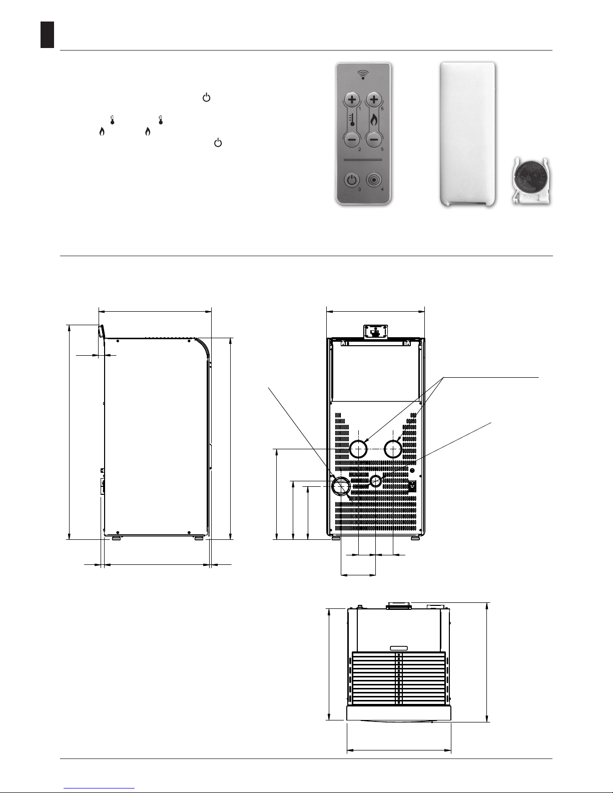
530 1020
570
8888
175
495
Ø 50 Air Intake
Ø 80 Smoke Outlet
Ø 80 Channeling (If Any)
1020
1084
269
296
457
30
The remote control (Fig. 3) used to adjust water temperature
power and the on/off functions for the pellet stove.
To start the stove, press key and the stove will
automatically enter the starting phase.
Press keys + (1) and - (2) to adjust temperature, and
use keys + (6) and - (5) to adjust operating power.
To turn off the stove, hold down key .
To replace the 3 volt battery located on the back of the
remote control, pull the centre of the cover and the lever
on the side of the same, replace the battery observing the
correct polarity (Fig. 4)
Fig. 3 Fig. 4
Technical Specification
Remote Control
REMARKS:
- measurements are approximate and may vary
based on to the aesthetics of the stove
- the positions of the tubes in the rear view are
indicative and tolerance of +/- 10 mm
- measures with a tolerance of about 10 mm
Mod. 14 - 14 C
TOLLERANZE GENERALI D I LAVORAZIONE
DIMENSIONI LINEARI
PRECISIONE
12
GRADO DI
FINO A
± 0,15
± 0,1
6
± 0,3
± 0,25
120
± 0,2
± 0,15
60
6
60
4000
± 0,8
± 0,6
1000
400
± 0,5
± 0,4
400
120
± 2
± 1,5
4000
2000
± 1
± 1,2
2000
1000 DA
A
± 2.5
± 3,5
OLTRE
AAAAA
DADADADADA
Spessore
Peso
Materiale
F
G
7488850 g
H
I
495
1020
530 1020
570
570
495
8888
175
495
Ø
50 Aspirazione Aria
Ø
80 Uscita Fumi
Ø80 Canalizzazione
(ove presente)
1020
1084
269
296
457
530
30
 Loading...