


INSTALLER USER
&
MANUAL
For
Denia 14 - 14D & Mia 16 - 16D

29
GB
Dear Customer,
We thank you for having chosen one of our products, the fruit of technological experience and of continual research for
a superior quality product in terms of safety, dependability, and service.
In this manual you will nd all the information and useful suggestions to use your product with the maximum safety
and efciency.
• Incorrect installation, incorrectly performed maintenance, improper use of the product release the manufacturer from
every eventual damage derived from the use of the stove.
• The unit cannot be used as an incinerator. Do not use fuels other than pellets.
• This manual has been realized by the manufacturer and constitutes an integral part of the product and must remain
with it during its entire lifetime. If the product is sold or transferred, be sure that the booklet is present since the
information contained in it are addressed to the buyer, and to all those persons of various titles who complete the
installation, use and maintenance.
• Carefully read the instructions and the technical information contained in this manual, before proceeding with the
installation, use, and any operation on the product.
• The observance of the indications contained in the present manual guarantees the safety of people and the product,
the economy of use and a longer functioning lifetime.
• Although the carefully studied design and the risk analysis done by our company has permitted the realization of a
safe product, in any case, before effecting any operation on the stove, it is recommended to keep said manual available and pay scrupulous attention to the instructions written therein.
• Be very careful when moving the ceramic details where present.
• Check the precise atness of the pavement where the product will be installed
• The wall where the product will be placed must not be constructed in wood, or in any case, made of an inammable
material, and in addition it is necessary to maintain a safety distance.
• While the stove is in operation, several parts of the stove (door, handle, sides) can reach high temperatures. Therefore pay attention and use the proper precautions, above all in the presence of children, elderly or disabled persons,
and animals.
• Assembly must be performed by authorized persons (Authorized Assistance Center).
• Diagrams and drawings are furnished for the purpose of illustration; the manufacturer, with the intent of pursuing a
policy of constant development and renewal of the product can, without any notice, make any modications that
are believed opportune.
• When the stove is working at its maximum speed, it is strongly suggested to wear gloves while handling with the
door for pellets loading and the door handle.
• It is prohibited to install in bedrooms or in explosive environments.
• Only use replacement parts recommended by the supplier.
In the event of a fire, disconnect the power supply, use an extinguisher and call the fire fighters if necessary.
After that contact the Authorized Assistance Center.
Never cover the body of the stove in any way or obstruct the openings placed on the upper side
when the device is operating. All our stoves are trial lighted on the construction line.
This instruction booklet is an integral part of the product: make sure that it always accompanies the appliance, even in
case of transfer to another owner or in the case of transfer to another place. In the event of damage or loss, request a
copy from the area technician.
These symbols indicate specific messages in this booklet:
ATTENTION:
This warning sign indicates that the message to which it refers should be carefully read and understood,
because failure to comply with what these notices say can cause serious damage to the stove and
put the user’s safety at risk.
INFORMATION:
This symbol is used to highlight information which is important for proper stove operation. Failure to
comply with these provision will compromise use of the stove and its operation will not be satisfactory.
eniaD tovesS 6D16-ia14D_M14-1
Cod. 001122
We highly recommend to turn to our Authorized Service Centre for the installation and the first
ignition of the device as it not only carries out the installation perfectly but also verifies the
regular operation of it.
30
GB
Our company declares that the stove conforms to the
following norms for the EC European Directive labelling:
• 2014/30 UE (regulation EMCD) and following
amendments;
• 2014/35 UE (Low Voltage Directive) and following
amendments;
• 2011/65 EU (RoHS 2 directive);
• The New Rules of Construction Products (CPRConstruction Products Regulation) No. 305/2011
regarding the construction world;
• For installations in Italy, please refer to UNI 10683/98
or following changes. For the water-thermo-sanitary
equipment, let the installer give you the conformity
declaration in compliance with L. 37/2008. While
installing the unit respect the local, national and Europen
rules;
• EN 55014-1; EN 55014-2; EN 61000-3-2; EN 61000-3-3;
EN 60335-1; EN 60335-2-102; EN 62233, EN 50581.
Safety information
Please carefully read this use and maintenance manual
before installing and operating the stove!
If clarication is needed, please contact the dealer or the
Authorized Assistance Center.
• The pellet stove must only be operated in living
environments. This stove, being controlled by an
electronic board, permits a completely automatic and
controlled combustion; the exchange, in fact, regulates
the lighting phase, 5 power levels and the shut down
stage, guaranteeing the safe operation of the stove.
• The basket used for combustion allows most of the ash
produced by the combustion of the pellets to fall into
the collection compartment. Nevertheless, check the
basket daily, given that not all pellets have high quality
standards (use only quality pellets recommended by the
manufacturer).
Responsibility
With the delivery of the present manual, we decline all
responsibility, both civil and penal, for accidents deriving
from the partial or total lack of observance of the
instructions contained herein.
We decline every responsibility derived from improper
use of the stove, from incorrect use by the user, from
unauthorized modications and/or repairs, from the use
of replacement parts that are not original for this model.
The manufacturer declines every civil or penal, direct or
indirect responsibility due to:
• Lack of maintenance;
• Failure to observe the instructions contained in the
manual;
• Use in non-conformity with the safety directives;
• Installation in non-conformity with the norms in force in
the country;
• Installation by unqualied or untrained personnel;
• Modications and repairs not authorized by the manu-
facturer;
• Use of non-original replacement parts;
• Exceptional events.
Norms and declarations of conformity
• Use only wood pellets;
• Keep / store the pellets in a cool
dry place;
• Never pour pellets directly on the hearth;
• The stove must be fueled only with quality
pellets with a diameter of 6 mm and a maximum
length of 30 mm of the type recommended by
the manufacturer.
• Before making the electrical connection of the
stove the discharge tubes must be connected
with the flue;
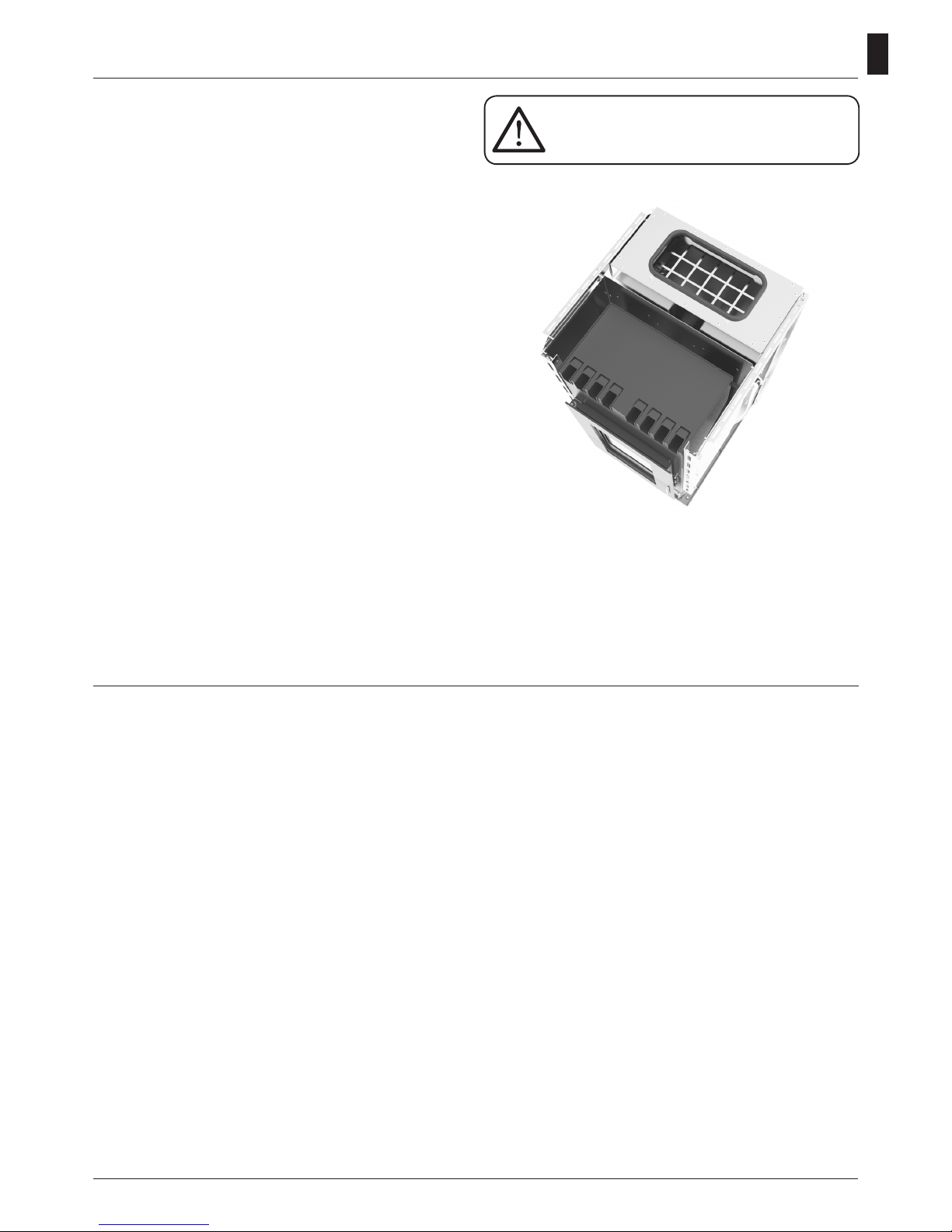
• The protective grill placed inside the pellet
container must never be removed;
• The environment where the stove is installed
must have a sufficient exchange of air;
• It is forbidden to operate the stove with the
door open or the glass broken;
• Do not use the stove as an incinerator; the stove
should be used only for the intended purpose;
• Any other use is considered improper and
therefore dangerous. Do not put in the hopper
other than wood pellets;
• When the stove is operating, the surfaces,
glass, handle and tubes become very hot:
during operation do not touch these parts
without adequate protection;
• Keep the fuel and other inflammable materials
off the stove.
31
GB
Charge pellet
Fuel is loaded from the upper part of the stove by opening
a door.
Pour the pellets in the hopper; vacuum contains about 23
kg of pellets. This is easier if performed in two steps:
• Pour half of the contents of the bag into the hopper and
wait for the fuel to settle on the bottom.
• Then pour in the second half;
• Keep the cover closed , after loading the pellets , the lid
of the fuel tank;
• Before closing the door load-pellet make sure that there
are no residues of pellets around the seal. If carefully
cleaned to avoid compromising the seals.
The stove is a product by heating, presents the external
surfaces particularly hot. For this reason, we recommend
extreme caution when operating in particular:
• Do not touch the stove body and the various components, do not approach the door , it could cause burns;
• Do not touch the exhaust fumes;
• Do not perform any type of cleaning;
• Do not dump the ashes;
• Do not open the ash tray;
• Be careful that children do not come near;
• The appliance is not intended for use by persons
(including children) with reduced physical, sensory or
mental capacities , or lack of experience or knowledge,
unless they have been given through the intermediary
of a person responsible for their safety, supervision or
instruction concerning use of the appliance;
• Do not use the stove as a ladder or scaffold;
• Do not put clothes to dry on the stove. Any clothes
hangers and suchlike must be kept a suitable distance
from the stove. - Risk of re
• Carefully explain that the stove is made from material
subjected to high temperatures for the elderly , the
disabled, and in particular for all children, keeping them
away from the stove during operation
• Do not touch the stove with wet hands: the stove has
electrical components that could produce sparks if
handled incorrectly.
• Never open the glass door of the pellet stove while the
stove is in operation.
• The stove must be connected to an electrical system
equipped with an earthing conductor in accordance with
regulations 73/23 and 93/98 EEC;
• The system must be of adequate electrical power
declared the stove;
• Do not wash the inside of the stove with water.
The water could damage the electrical insulation, causing
electric shock;
• Do not expose your body to hot air for a long time. Do
not overheat the room you are in and where the stove is
installed.
This can damage the physical conditions and cause
health problems;
• Do not expose to direct the ow of hot air plants or
animals;
• The pellet stove is not a cooking element;
• External surfaces during operation can become very
hot. Do not touch them except with the appropriate
protection.
Instructions for safe and efficient use
Never remove the protection grille in the
hopper. When filling, do not let the sack
of pellets touch any hot surfaces.
32
GB
For proper functioning and a good temperature distribution,
the stove shoul be positioned in a location where it is able
to take in the air necessary for combustion of the pellet
(about 40 m3/h must be available, as laid down in the
standard governing the installation and in accordance with
local national standards).
The volume of the room must not be less than 30 m3.
The air must come in through permanent openings made
in walls (in proximity to the stove) which give onto the
outside, with a minimum cross-section area of 100 cm2.
These openings must be made in such a way that it is not
possible for then to be obstructed in any way. Alternatively,
the air can be taken from rooms adjacent to the one which
needs ventilating, as long as they are provided with an air
intake from the outside, and are not used as bedrooms or
bathrooms, and provided there is no re risk such as there
is for example in garages, woodsheds, and storerooms,
with particular reference to what is laid down in current
standards.
It is not permissible to install the stove in
bedrooms, bathrooms, or in a room where
another heating appliance is installed
(fireplace, stove etc.) which does not have its own
independent air intake.
Locating the stove in a room with an explosive
atmosphere is prohibited.
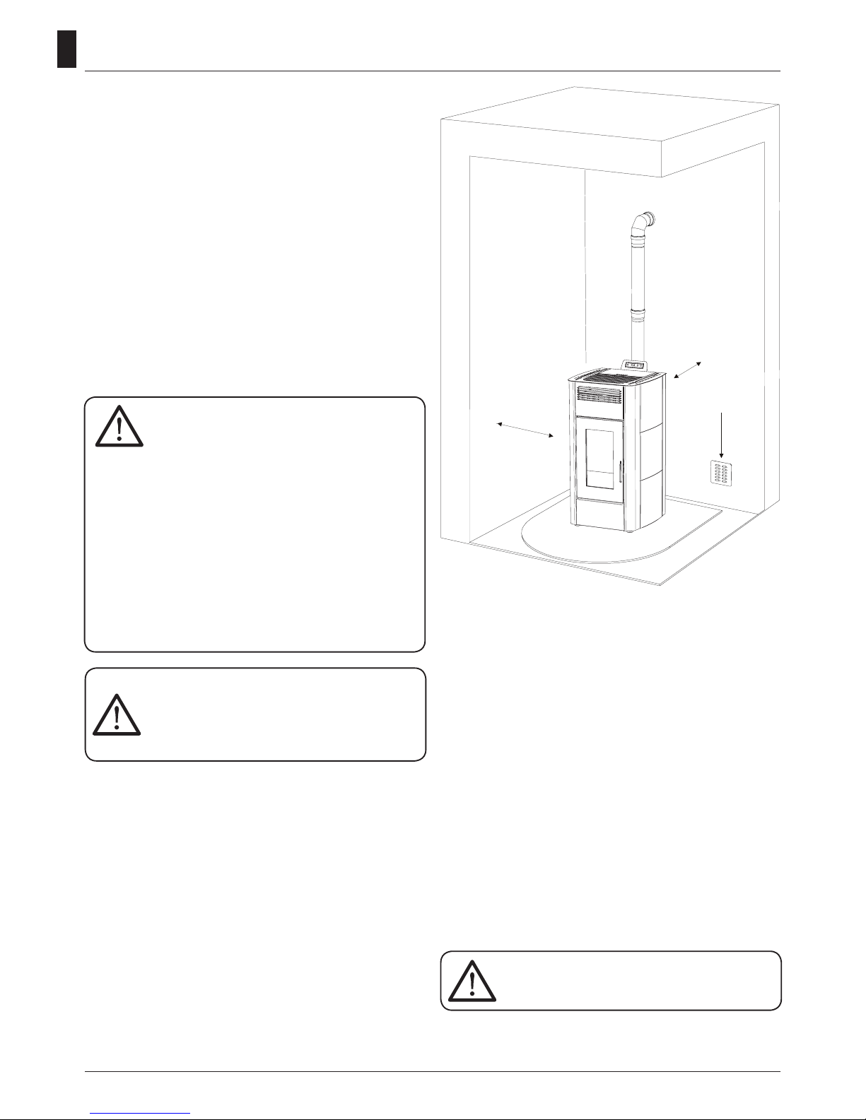
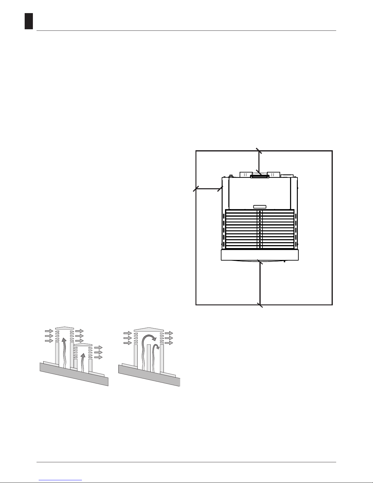
The floor of the room where the stove is to be
installed must be strong enough to take its weight. If
walls are flammable, maintain a minimum distance
of 20 cm at the rear (A), of 30 cm at the side (B) and
100 cm at the front. If the room contains objects
which are believed to be particularly delicate, such
as drapes, sofas and other furniture, their distance
from the stove should be considerably increased.
In the presence of wood floors, install a
floor protection surface in compliance
with the rules in force in the country
Operating area
30 cm
(B)
Min.
100 cm
2
20 cm (A)
Connection to the external air intake
It is essential that at least as much air must be able to ow
into the room where the stove is installed as is required for
proper combustion in the appliance and for the ventilation
of the room. This can be effected by means of permanent
openings in the walls of the room to be ventilated, which
give onto the outside, or by single or collective ventilation
ducts.
For this purpose, on the external wall near the stove, a
hole must be made with a minimum free cross-section of
100 cm2. (equivalent to a round hole of 10 cm diameter or
a square hole 10x10 cm) protected by a grille on the inside
and the outside.
The air intake must also:
•
communicate directly with the room where the stove is
installed
•
be protected by a grille, metal mesh or suitable guard, as
long as this does not reduce the area below the minimum.
•
positioned in such a way as to be impossible to obstruct.
If the stove is installed on a flammable
floor it must be interposed with a slab of
insulating material to heat it protrudes at
least 20 cm on the sides and 40 cm on the
front.
33
GB
Connection to the flue pipe
The ue pipe must have internal dimensions not larger
than 20x20 cm, or diameter 20 cm. In the event of larger
dimensions, or of the ue pipe being in poor condition ( for
example cracks, poor insulation, etc.), it is advisable to t
a stainless steel pipe of suitable diameter inside the ue
pipe throughout its length, right up to the top.
Check with suitable instruments that there is a draught
between 3 Pa and 10 Pa. This type of connection ensures
the evacuation of the fumes even in the event of a
temporary power cut.
At the bottom of the ue pipe, provide an inspection cap
to allow periodic checking and cleaning, which must be
done annually. Make a gas-tight connection to the ue
pipe, using pipes and connectors as recommended by us.
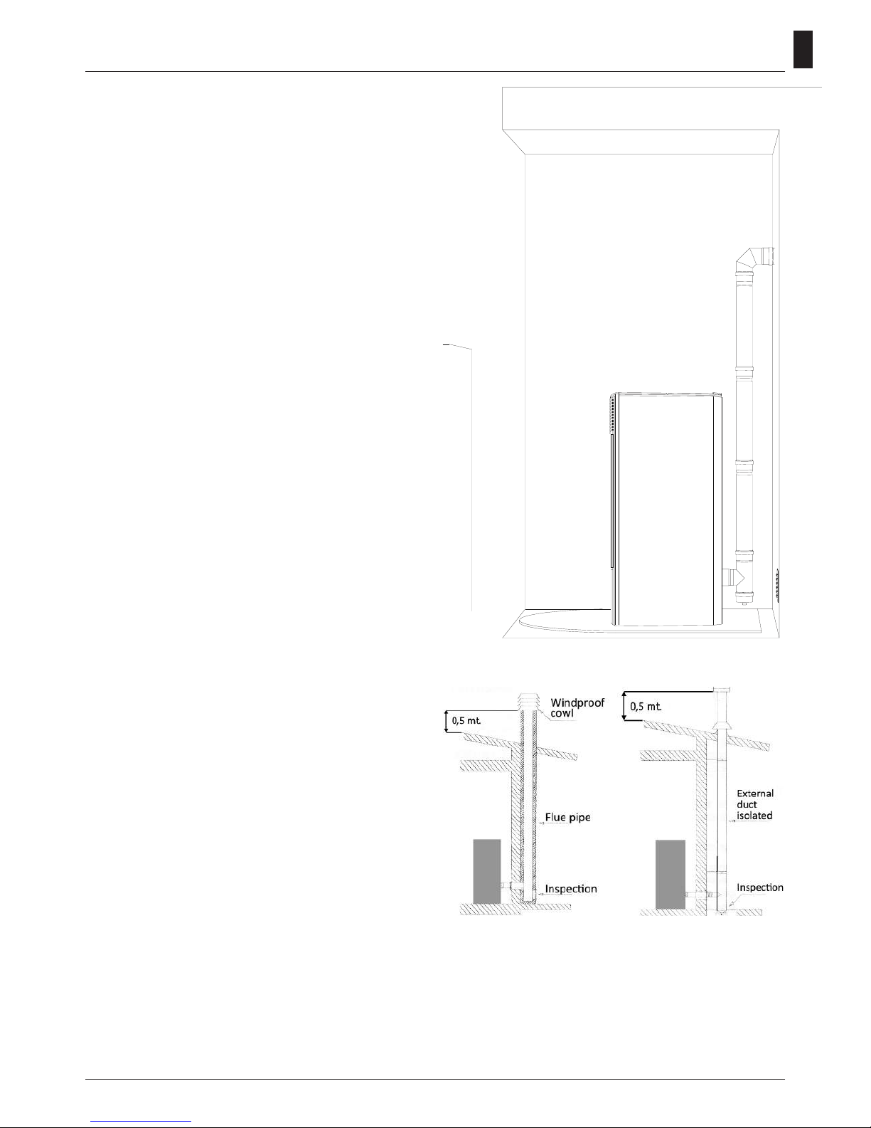
You must ensure that a windproof cowl should be tted
which complies with the standards in force
Connection to an external flue with insulated or
double-wall pipe
The only type of pipe which is permissible is insulated
(double-walled) stainless steel, smooth on the inside,
xed to the wall. Flexible stainless steel pipe must not be
used. At the bottom of the ue pipe, provide an inspection
cap to allow periodic checking and cleaning, which must
be done annually. Make a gas-tight connection to the ue
pipe, using pipes and connectors as recommended by us.
You must ensure that a windproof cowl should be tted
which complies with the standards in force.
Check with suitable instruments that there is a draught
between 3 Pa and 10 Pa.
Connection to the flue pipe
For proper functioning, the connecting pipe between the
stove and the chimney or ue duct must have a slope of
not less than 3% in the horizontal stretches, the length of
which must not exceed 2 metres and the vertical distance
between one tee connector and another (change of
direction) must not be less than 1,5 m.
Check with suitable instruments that there is a draught
between 3 Pa and 10 Pa. At the botton of the ue pipe,
provide an inspection cap to allow periodic checking and
cleaning, which must be done annually.
Make a gas-tight connection to the ue pipe, using pipes
and connectors as recommended by us. You must ensure
that a windproof cowl should be tted which complies
with the standards in force.
Fig. 3: connection to an
external ue with insulated
or double-wall pipe.
Fig. 2: connection to the
ue pipe.
34
GB
Fireplace flue gas
Avoid contact with combustible materials (example:
wooden beams) and in any case provide for their insulation
with ame retardant material. In case of pipe penetrations
through roofs or walls is recommended to use special
kits crossing, certicates, are available commercially. In
the event of a chimney re, turn off the stove, disconnect
from the network and never open the door. Then call the
authorities.
The chimney cap
The chimney cap must respect the following requirements:
• It must have the equivalent diameter and internal form
of the ue.
• It must have a useful outlet diameter of not less than
double that of the ue.
• The chimney cap on the roof or that remains in contact
with the outside (for example, in case of open lofts or attics), must be covered with elements in brick or tile and
must, in any case, be well insulated.
• It must be constructed to prevent rain, snow, and extraneous bodies from entering the ue and so that the
discharge of the products of combustion is not inhibited
by wind from any quarter or strength (wind-proof chimney cap).
• The chimney cap must be positioned in such a way as
to guarantee the adequate dispersion and dilution of the
products of combustion and in any case, must be out of
the reux zone. This zone has different dimensions and
forms according to the angle of inclination of the roof so
it is necessary to adopt minimum heights (Fig. 2).
• The chimney cap must be a wind-proof type and must
be above the ridge.
• Eventual structures or other obstacles that are higher
than the chimney cap must not be too close to the
chimney cap itself.
• The device should not be installed in the ue shared.
Fig. 5: Characteristics of chimney
YES NO
REMARKS:
- the appliance must be installed by a qualied technician in
possession of the technical and professional requirements
according to the DM37/2008 that, under its responsibility,
to ensure compliance with the rules of good technique.
- you need to keep in mind all laws and national, regional,
provincial and municipal laws of the country in which you
installed the device
- check that the oor is not ammable: if necessary use a
suitable platform
- in the room where the generator must be installed to
heat must not pre-exist or be installed with an extractor
hood or ventilation ducts of the collective type.
Should these devices be located in adjacent rooms
communicating with the installation, and ‘prohibited the
simultaneous use of the heat generator, where there is a
risk that one of the two rooms being placed in depression
than the other
- it is not permissible to install in bedrooms or bathrooms.
Connection of the canalization pipe
The two air outputs placed on the back of the stove
only one tube of 80mm diameter and 8 linear meters of
maximum length.
You have to consider a loss around 1 meter of the linear
tract for each bend of 45° (ex.: maximal distance without
bends: 8 meters; maximal distance with one bend 8-1=7
meters).
Distance to objects
It is also recommended to keep the pellets and all
ammable materials at a suitable distance from the stove.
30 cm
100 cm
20 cm

35
GB
How to change the operating power
You can change the operating power from a min. value of
1 to a max. value of 5. You can also choose the “Auto”.
Press the key 6 (6) to increase or press
5
6
(5) to
reduce it.
When you stop working on the power menu for a while,
the stove will automatically leave the menu itself.
Functional keys
1. Temperature increase: using this key you can increase
the wished temperature from a min. value of 7°C to a max.
value of 40°C.
2. Temperature decrease: using this key you can reduce
the wished temperature from a max. value of 40° C to a
min. value of 7°C.
3. Key SET: push this button to enter the programming
menu of the stove.
4. Key on/off: keep this button pushed for two seconds
to switch the stove on or off.
5. Operating power decrease: using this key you can
reduce the working power from a max. value of 5 to a min.
value of 1.
6. Operating power increase: using this key you can
increase the working power from a min. value of 1 to a
max. value of 5.
Function indicators
Chronothermostat
This signalises that the automatic single or daily switching
on or off of the stove is on. The automatic programming
can be set only using the remote control.
Resistance indicator
This works only when the stove is lighting up to indicate
that the resistance is warming the air to burn pellets.
Endless screw
6
This switches on every time pellets are being loaded in
the stove.
Smokes extractor 6
This signalises the smokes ventilator is working.
Exchanger
6
This indicates the room ventilator is working.
Control board
1. Temperature increase
2. Temperature decrease
3. Key SET
4. Key on/off
5. Operating power decrease
6. Operating power increase
Alarm indicator
4
5
6
This lights up in the event of an alarm or functioning defect.
You can read the kind of signalised alarm on the display.
Remote control reception
Stove setting
How to change the wished room temperature
You can change the temperature whenever you want.
Press the keys
1
6
1
6
(1) and
1
6
1
2
3
SET
4
5
6
(2) to modify the wished
value. When you stop working on the Set temperature
menu for a while, the stove will automatically leave the
menu itself.
36
GB
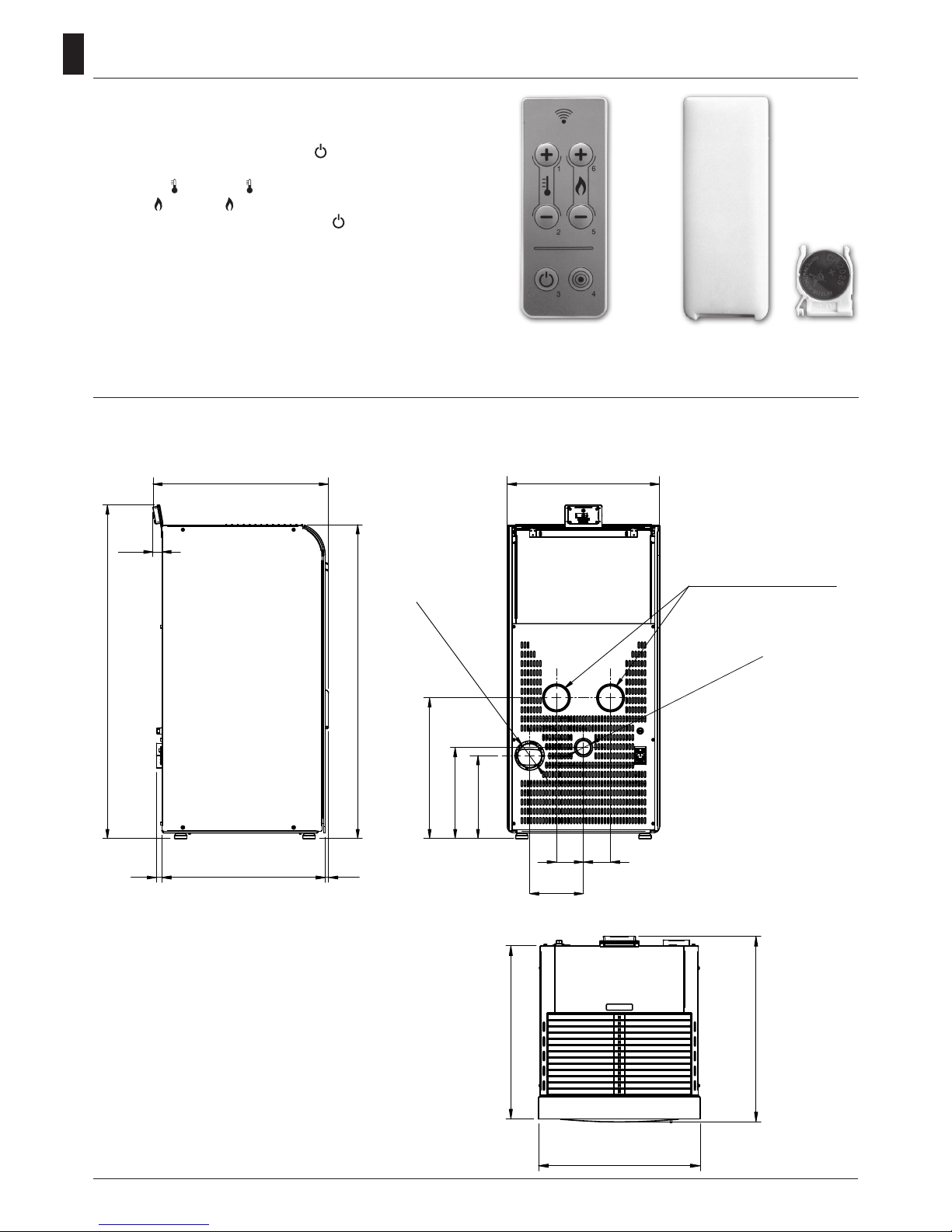
530 1020
570
8888
175
495
Ø 50 Air Intake
Ø 80 Smoke Outlet
Ø 80 Channeling (If Any)
1020
1084
269
296
457
30
The remote control (Fig. 3) used to adjust water temperature
power and the on/off functions for the pellet stove.
To start the stove, press key and the stove will
automatically enter the starting phase.
Press keys + (1) and - (2) to adjust temperature, and
use keys + (6) and - (5) to adjust operating power.
To turn off the stove, hold down key .
To replace the 3 volt battery located on the back of the
remote control, pull the centre of the cover and the lever
on the side of the same, replace the battery observing the
correct polarity (Fig. 4)
Fig. 3 Fig. 4
Technical Specification
Remote Control
REMARKS:
- measurements are approximate and may vary
based on to the aesthetics of the stove
- the positions of the tubes in the rear view are
indicative and tolerance of +/- 10 mm
- measures with a tolerance of about 10 mm
Mod. 14 - 14 C
TOLLERANZE GENERALI D I LAVORAZIONE
DIMENSIONI LINEARI
PRECISIONE
12
GRADO DI
FINO A
± 0,15
± 0,1
6
± 0,3
± 0,25
120
± 0,2
± 0,15
60
6
60
4000
± 0,8
± 0,6
1000
400
± 0,5
± 0,4
400
120
± 2
± 1,5
4000
2000
± 1
± 1,2
2000
1000 DA
A
± 2.5
± 3,5
OLTRE
AAAAA
DADADADADA
Spessore
Peso
Materiale
F
G
7488850 g
H
I
495
1020
530 1020
570
570
495
8888
175
495
Ø
50 Aspirazione Aria
Ø
80 Uscita Fumi
Ø80 Canalizzazione
(ove presente)
1020
1084
269
296
457
530
30

37
GB
REMARKS:
- measurements are approximate and may
vary based on to the aesthetics of the stove
- the positions of the tubes in the rear view
are indicative and tolerance of +/- 10 mm
- measures with a tolerance of about 10 mm
Mod. 16 - 16 C
TOLLERANZE GENERALI DI LAVORAZIONE
DIMENSIONI LINEARI
PRECISIONE
12
GRADO DI
FINO A
± 0,15
± 0,1
6
± 0,3
± 0,25
120
± 0,2
± 0,15
60
6
60
4000
± 0,8
± 0,6
1000
400
± 0,5
± 0,4
400
120
± 2
± 1,5
4000
2000
± 1
± 1,2
2000
1000 DA
A
± 2.5
± 3,5
OLTRE
AAAAA
DADADADADA
Spessore
Peso
Materiale
7488850 g
495
1080
530 1020
570
570
495
8888
175
495
Ø
50 Aspirazione Aria
Ø 80 Uscita Fumi
Ø80 Canalizzazione
(ove presente)
1080
1144
329
356
517
530
30
530 1020
570
8888
175
495
Ø 50 Air Intake
Ø 80 Smoke Outlet
Ø 80 Channeling
(if Any)
1080
1144
329
356
517
30

38
GB
PARAMETER
UNIT OF
MEASURE
CAYENNE 14 - 14 C CAYENNE 16 - 16 C
Heat input kW 13,2 16,3
Nominal heat output kW 12,5 15,2
Reduced heat output kW 3,7 3,7
CO concentration at nominal
reference (13% O2)
mg/m
3
104,82 94,85
CO concentration at reduced
reference (13% O2)
mg/m
3
409,5 409,5
Nominal efciency % 94,76 93,48
Reduced efciency % 98 98
Pellet consumption (min-max) Kg/h 0,78 - 2,72 0,78 - 3,44
Heated surface mc 340 400
Flue gas ow rate (min-max) g/s 2,83 - 7,29 2,83 - 8,53
Draft advised (min-max) Pa 3 - 12 3 - 12
Flue gas temperature (min-max) °C 46 - 112 46 - 139
Tank capacity Kg 23 23
Recommended fuel
(ø x H)
mm
pellet 6 x 30 pellet 6 x 30
Diameter smoke outlet tube mm 80 80
Diametro canalizzazione mm 80 80
Diameter air intake mm 50 50
Nominal voltage V 230 230
Nominal frequency Hz 50 50
Power consumption max W 400 400
Stove weight Kg 135 - 140 140 - 145
N° Test Report K19052016T1
The pellets are cylinders of compressed wood, produced from sawdust and wood processing (chips and
sawdust), generally produced by sawmills and carpenters. The binding capacity of the lignin contained
in wood, allows to obtain a compact product without adding additives and foreign chemicals to the
wood, is therefore obtained a natural fuel with high yield.
The use of expired pellets or any other unsuitable material can damage parts of
the stove and impair proper operation: this can lead to the termination of the
guarantee, and its producer responsibility.
For our stoves use pellets diameter 6 mm, length 30 mm and a maximum
of 8% moisture. Store the pellets away from heat sources and not in
humid environments or with explosive atmospheres.
Pellet
It is recommended that the control of emissions after installation.

39
GB
Charge pellet
Fuel is loaded from the upper part of the stove by opening
a door. Pour the pellets in the hopper. When empty, it will
hold slightly more than 23 kg.
This is easier if performed in two steps:
•
Pour half of the contents of the bag into the hopper and
wait for the fuel to settle on the bottom.
•
Then pour in the rest.
The brazier should be cleaned before each
starting.
Never remove the protection grille in the
hopper. When filling, do not let the sack of
pellets touch any hot surfaces.
Remove any components which might
burn from the firebox and from the glass
(various instructions and adhesive labels).
First lighting of the stove
• Before switching on, make sure that the grate is clean and
empty of any pellet residues from previous combustions.
Otherwise make sure you empty and clean it
• Fill the container 3/4 full with the pellets recommended
by the manufacturer
• Connect the stove to an electrical outlet with the cable
that has been supplied
• Press the lighting switch located on the back part of the
stove
• The upper display will read “OFF”
• Press the button for 2 seconds. After a few moments
the smoke extractor and the lighting resistor will start
and the display will read “START”; The led resistance is
switched on
• After 1 minute the display will read “LOAD PELLET”, the
stove will load the pellets and continue lighting the resistor
• Once the appropriate temperature has been reached
the display will read “FLAME LIGHT”: this means that the
stove has begun the last phase in lighting, at the end of
which the stove will be completely operational; The led
resistence is switched off
• After some minutes the display will show the words
“WORK” alternating room temperature and current working
power. The stove is now completely on
• When the stove reaches the set temperature, the display
will show “MODULATION”.
Stove start up
We highly recommend to turn to our
Authorized Service Centre for the
installation and the first ignition of the
device as it not only carries out the installation
perfectly but also verifies the regular operation of it.
During the first lighting the environment should
be well ventilated since during the first hours of
operation unpleasant odours could develop due to
the physical stabilizing of the paint and from the
grease in the tube bundle.
Before lighting a small amount of smoke
may fill the combustion chamber.
Stove switching off
To switch off the stove, press the key on the control
board until you read “CLEANING FINAL” on the display.
After the stove has been switched off, the fan continues
working for a set time in order to grant a fast smokes
exhaust from the combustion chamber.
If you have a model with remote control, you just need to
switch the remote control off keeping the key pressed for
2 seconds and conrming the selection pressing the key
SEND.
If you try to switch on the stove during this phase, the
display will show “waiting cooling” (that means wait for
cooling) in order to inform you a switching off phase is
running. Wait until the cooling phase is completely off and
the display shows “OFF” before staring a new light up.
REMARKS:
• Do not continuously turn the stove on and off as this
could provoke sparks that could shorten the life of the
electrical components.
• Do not touch the stove with wet hands: the stove
has electrical components that could produce sparks
if handled incorrectly. Only authorized technicians can
resolve possible problems.
• Do not remove any screws from the re chamber without
rst lubricating them well.
• Never open the glass door of the pellet stove while the
stove is in operation.
• Be sure that the brazier basket is positioned correctly.
• The ue system must be suitable for inspecion. If it cannot
be removed, it must have some holes for inspection and
cleaning.

40
GB
Programming menu
Menu 02 SET CLOCK
To access the set clock option, press the “SET” button (3), with the button - (5) scroll through the submenus until MENU
02 - SET CLOCK and with buttons 1 and 2 select the current day. Press the “SET” button (3) to conrm.
Then use buttons 1 and 2 to set the time and press “SET” (3) to advance to the minutes setting by pressing buttons 1
and 2. By pressing set again it’s possible to access various submenus in order to set the date, day, month, and year.
To do so, repeat the steps indicated above, using buttons 1, 2, and 3.
The following table briey describes the structure of the menu, focusing only on those selections which are available
to the user.
Set the current time and date. The device comes equipped
with a lithium battery that allows the internal clock to
operate autonomously for over 3-5 years.
Menu 03 SET CHRONO
Press the “SET” button (3) and then button 5 to arrive at the desired menu; press “SET” (3) to enter.
Enter menu M-3-1 and with buttons 1 and 2 select whether or not to activate the thermostat (on/off), which allows you
to program the automatic ignition of the stove.
Once the thermostat is activated/deactivated, press button “4” (OFF) and continue scrolling though the submenus
using button 5. Select which submenu you wish to enter in order to access the daily, weekly, and weekend programmes.
To set the ignition times and days repeat the previous steps:
- access the submenu using “SET” (3)
- adjust the days, times, and activation status (on/off) with buttons 1 and 2
- conrm by pressing the “SET” button (3)
- exit from the submenu/menu with button 4 to turn it off
The following table briey describes the structure of the menu, focusing only on those selections which are available
to the user.
level 1 level 2 level 3 level 4 value
02 - set clock
01 - day day of the week
02 - hour hour
03 - minutes minutes
04 - day day of the month
05 - month month
06 - year year
level 1 level 2 level 3 level 4 value
03 - set thermostat
01 -
activate thermos.
01 -
activate thermos.
on/off
02 -
day programme
01 -
daily thermostat
on/off
02 - start 1 day hour
03 - stop 1 day hour
04 - start 2 day hour
05 - stop 2 day hour
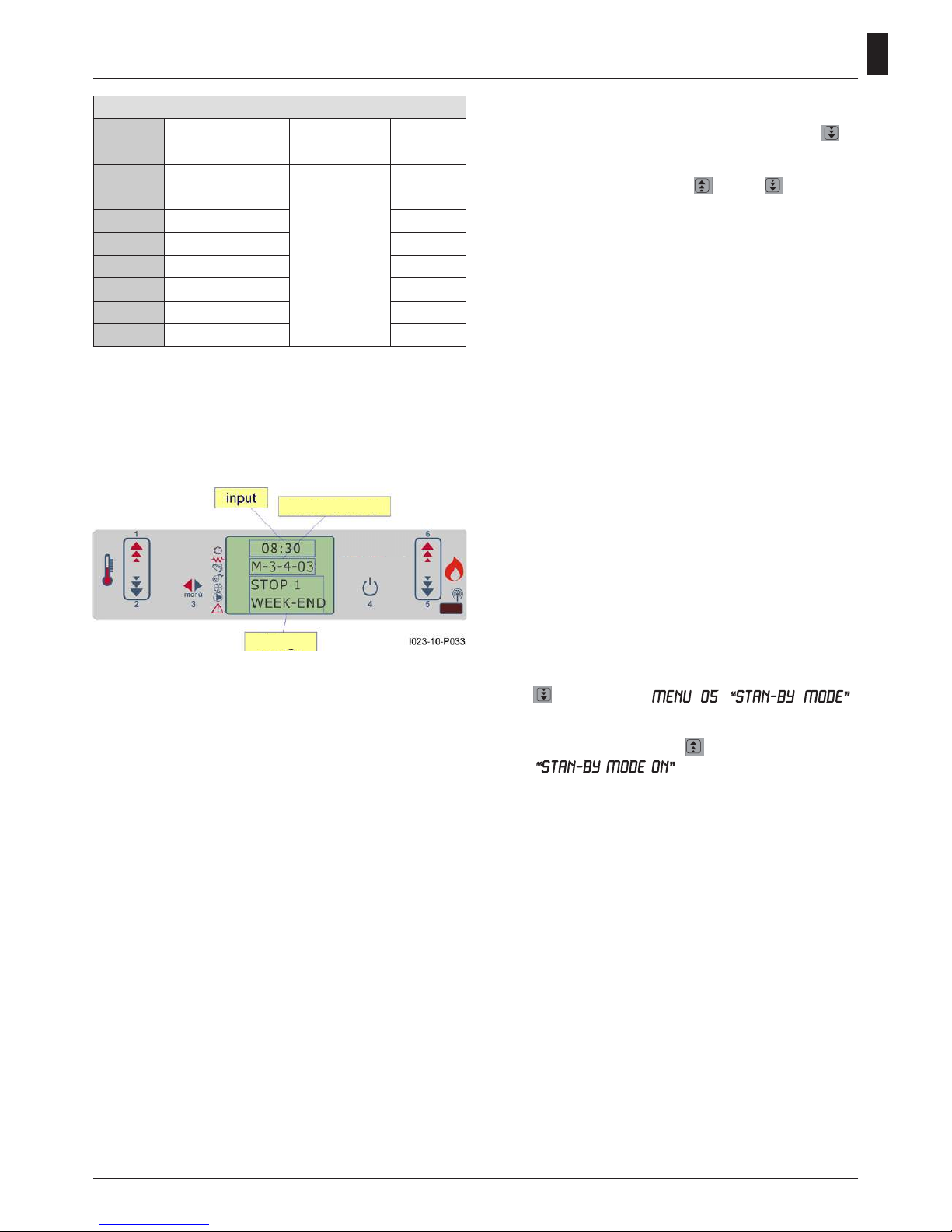
menu level
dialogue
MENU
CLOCK

41
GB
level 1 level 2 level 3 level 4 value
03 - set thermostat
03 - week program.
01 - week thermostat on/off
02 - start program. 1 hour
03 - stop program. 1 hour
04 - monday progr. 1 on/off
05 - tuesday progr. 1 on/off
06 -
wednesday prog. 1
on/off
07 - thursday prog 1 on/off
08 - friday prog 1 on/off
09 - saturday prog 1 on/off
10 - sunday prog 1 on/off
11 - start program. 2 hour
12 - stop program. 2 hour
13 - monday progr. 2 on/off
14 - tuesday progr. 2 on/off
15 -
wednesday prog. 2
on/off
16 - thursday prog 2 on/off
17 - friday prog 2 on/off
18 - saturday prog 2 on/off
19 - sunday prog 2 on/off
20 - start program. 3 hour
21 - stop program. 3 hour
22 - monday progr. 3 on/off
23 - tuesday progr. 3 on/off
24 -
wednesday prog. 3
on/off
25 - thursday prog 3 on/off
26 - friday prog 3 on/off
27 - saturday prog 3 on/off
28 - sunday prog 3 on/off
29 - start program. 4 hour
30 - stop program. 4 hour
31 - monday progr. 4 on/off
32 - tuesday progr. 4 on/off
33 -
wednesday prog. 4
on/off
34 - thursday prog. 4 on/off
35 - friday prog. 4 on/off
36 - saturday prog. 4 on/off
37 - sunday prog. 4 on/off
04 -
week-end program.
01 - therm. week-end
02 - start 1
03 - stop 1
04 - start 2
05 - stop 2

42
GB
selection meaning possible values
START 1 activation time time - OFF
STOP 1 shut-off time time - OFF
START 2 activation time time - OFF
STOP 2 shut-off time time - OFF
Menu 03 SET CHRONO
Submenu 03 - 01 - activate thermostat
This allows you to activate and deactivate all of the
functions of the thermostat
Submenu 03 - 02 - daily programme
This allows you to enable, disable, and set the daily
functions of the thermostat.
Submenu 03 - 03 - weekly programme
This allows you to enable, disable, and set the weekly
functions of the thermostat.
It’s possible to set two operating ranges delimited by the
times set according to the following table where the OFF
setting tells the clock to ignore the command:
The weekly programmer has 4 independent programmes
whose nal effect is composed of the combination of the
4 individual programmes.
The weekly programmer can be activated or deactivated.
Additionally, by setting OFF in the time eld, the clock
ignores the corresponding command.
Plan programming carefully in order to
avoid overlapping activation/deactivation
times in a single day in different
programmes.
PROGRAMME 1
menu level selection meaning
possible values
02-03-02 START PROGRAM 1 activation time time - OFF
02-03-03 STOP PROGRAM 1 shut-off time time - OFF
02-03-04 MONDAY PROGRAM 1
reference day
on/off
02-03-05 TUESDAY PROG 1 on/off
02-03-06 WEDNESDAY PROG 1 on/off
02-03-07 THURSDAY PROGR 1 on/off
02-03-08 FRIDAY PROGRAM 1 on/off
02-03-09 SATURDAY PROGR 1 on/off
02-03-10 SUNDAY PROGR 1 on/off
PROGRAMME 2
menu level selection meaning
possible values
03-03-11 START PROGRAM 2 activation time time - OFF
03-03-12 STOP PROGRAM 2 shut-off time time - OFF
03-03-13 MONDAY PROGRAM 2
reference day
on/off
03-03-14 TUESDAY PROG 2 on/off
03-03-15 WEDNESDAY PROG 2 on/off
03-03-16 THURSDAY PROGR 2 on/off
03-03-17 FRIDAY PROGRAM 2 on/off
03-03-18 SATURDAY PROGR 2 on/off
03-03-19 SUNDAY PROGR 2 on/off
PROGRAMME 3
menu level selection meaning
possible values
03-03-20 START PROGRAM 3 activation time time - OFF
03-03-21 STOP PROGRAM 3 shut-off time time - OFF
03-03-22 MONDAY PROGRAM 3
reference day
on/off
03-03-23 TUESDAY PROG 3 on/off
03-03-24 WEDNESDAY PROG 3 on/off
03-03-25 THURSDAY PROGR 3 on/off
03-03-26 FRIDAY PROGRAM 3 on/off
03-03-27 SATURDAY PROGR 3 on/off
03-03-28 SUNDAY PROGR 3 on/off
menu level
dialogue
ENABLE
THERMOSTAT
menu level
dialogue
DAY
menu level
dialogue
43
GB
Submenu 03 - 04 - program week-end
This allows you to enable, disable, and set the weekend
functions of the thermostat (days 5 and 6, or Saturday and
Sunday).
REMARKS:
- in order to avoid confusion and unwanted start-ups or
shutdowns, activate only one programme at a time unless
you know exactly what you’d like to achieve
- deactivate the daily program if you want to use the
weekly program
- always leave the weekend programme deactivated if you
use weekly programmes 1, 2, 3, and 4.
- activate the weekend programme only after you have
deactivated the weekly programme.
PROGRAMME 4
menu level selection meaning
possible values
03-03-29 START PROGRAM 4 activation time time - OFF
03-03-30 STOP PROGRAM 4 shut-off time time - OFF
03-03-31 MONDAY PROGRAM 4
reference day
on/off
03-03-32 TUESDAY PROG 4 on/off
03-03-33 WEDNESDAY PROG 4 on/off
03-03-34 THURSDAY PROGR 4 on/off
03-03-35 FRIDAY PROGRAM 4 on/off
03-03-36 SATURDAY PROGR 4 on/off
03-03-37 SUNDAY PROGR 4 on/off
Menu 04 - select language
Press the SET button to access the menu and press
5
6
(5)
up to the MENU 04 - SELECT LANGUAGE.
Then press the SET button to access the menu. Select the
desired language using the keys
1
6
(1) and
1
2
3
SET
4
5
6
(2)
Stand-by mode
This mode allows the automatic shutdown of the stove
once it reaches the temperature set on SET.
When this happens, the stove will wait a few minutes
(factory setting), after which will turn off automatically if
the temperature of the room in the meantime has always
maintained above the set.
Once turned off as a result of this condition, the stove will
automatically turn on only when the ambient temperature
will drop to 2 °C below the set temperature in the oven
(example: SET=24 °C and ambient temperature = 21 °C).
If the stove is turned off for the sleep-mode, although
there is an ignition programmed this will be ignored and
the heater will turn back on only to lower the temperature
as explained above.
The sleep timer is instead always respected if the stove is
in STAND-BY and is turned off manually by pressing the
OFF button; doing so the stove will shut down permanently
rekindling not more, less than expected from the ignition
weekly programming.
Enabling stand-by mode
Press the SET (3) to access the menu and with the
button
5
6
(5) reach the MENU 05 (“STAN-BY MODE”).
Then press SET (3) to access it; STAND-BY function is set
by default to OFF.
To activate this feature, press
1
6
(1), on the display you
will see “STAN-BY MODE ON”.
Press SET (3) to conrm and then OFF (4) to leave.
The STAND-BY mode is now active.
menu level
dialogue
44
GB
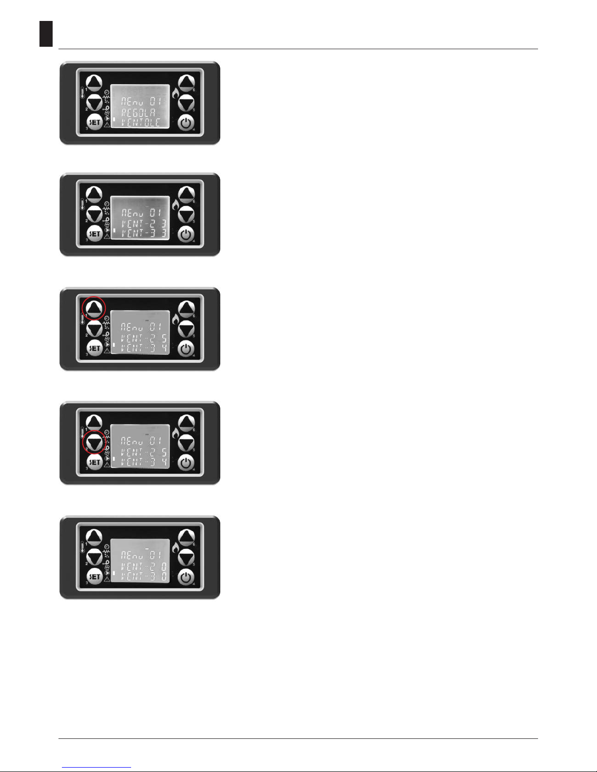
1. Press the SET button.
Will appear on the display MENU 01 SETTING FANS
2. Pressing the SET key to access the menu to set the speed of
your funnel fans
3. Set the speed using the buttons 1 and 2. With key 1 you set
the speed of the right fan, with key 2 you set the speed of the
left fan
4. To turn off the fans of the funnel, set the speed to 0
Fan speed adjustment channeling (if any)
45
GB
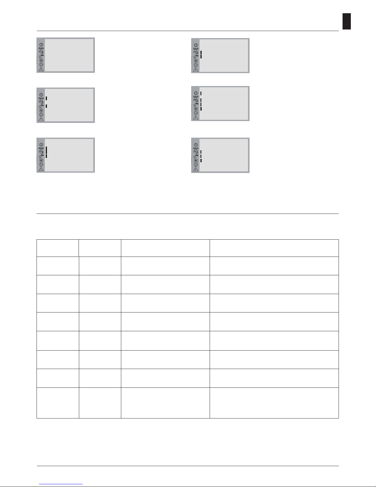
Display informations
Alarm signals
OFF
The stove is off.
21:10
22°C P-1
OFF
START
The stove is switching on.
Resistance and smokes extractor
are on.
21:10
22°C P-1
OFF
14:35
21°C P-2
START
LOAD PELLET
The stove starts loading pellets in
the brazier.
Resistance, smokes extractor and
gear motor are on.
21:10
22°C P-1
OFF
14:35
21°C P-2
START
14:35
21°C P-2
LOAD
pellet
FLAME LIGHT
The stove starts loading pellets in
the brazier.
Smokes extractor and gear mo-
tor are on.
21:10
22°C P-1
OFF
14:35
21°C P-2
START
14:35
21°C P-2
LOAD
pellet
14:35
21°C P-2
FLAME
LIGHT
CLEANING FIRE-POT
The stove is cleaning the brazier.
The smokes extractor is working
at its max. speed and the pellets
loading is minimal.
21:10
22°C P-1
OFF
14:35
21°C P-2
START
14:35
21°C P-2
LOAD
pellet
14:35
21°C P-2
FLAME
LIGHT
15:18
21°C P-3
WORK
(5)
16:40
22°C P-2
CLEANING
FIRE-POT
WORK
The stove is working, in this case
with working power 3. Detected
room temperature is 21°C. Smokes
ventilator, gear motor and room
ventilator are on during this phase.
21:10
22°C P-1
OFF
14:35
21°C P-2
START
14:35
21°C P-2
LOAD
pellet
14:35
21°C P-2
FLAME
LIGHT
15:18
21°C P-3
WORK
(5)
Regular checks should be carried out by the user, who should only contact the Authorized Assistance Center
if no solution is found.
In the event of a working defect, the system informs the user about the type of failure occurred.
The following table summarises the alarms, kind of problem and possible solution:
Upper
Display
Lower
Display
Kind of failure Solution
AL 5
The cannot start up
This is the rst light-up
Fill in the tank with pellets
Start up again
AL 6
NO
PELLET
The pellet stove switched off while work-
ing
Fill in the tank with pellets
AL 2
PROBE
EXHAUST
The smokes sensor is broken or not
connected to the pcb
Contact an Authorized Assistance Center
AL 7
SAFETY
THERMAL
The stove is overheated
Reset the thermostat manually. If the problem persists,
contact an Authorized Assistance Center.
COOL FIRE
There is no power supply
As soon as the power supply is back, the stove starts a cooling cycle. After completing the cycle it starts working automatically
AL 4
FAN
FAILURE
Smokes extractor blocked or broken Contact an Authorized Assistance Center
AL 8
FAILURE
DEPRESS
Obstructed ue
Clean the ue or check there are no obstructed grids near the
smokes exhaust
SERVICE
The stove has worked for 1300 hours.
Supplementary maintenance required
Contact an
Authorized Assistance Center

46
GB
Maintenance and cleaning of the stove
Before effecting any maintenance operation or cleaning
on the stove, take the following precautions:
• be sure that all parts of the stove are cold.
• be sure that the ashes are completely cold.
• be sure that the general switch is in the “OFF” position.
• be sure that the plug is pulled out of the socket to avoid
accidental contact.
• once the maintenance phase is completed check that
everything is in order as per before the intervention (the
brazier is placed correctly).
Follow carefully the following cleaning
instructions. Failure to follow these
instructions could create problems with
the operation of the stove.
Cleaning the glass
The glass is a self cleaning type, therefore, while the
stove is working, a veil of air is blown across its surface to
remove ash and dirt; nevertheless over a period of several
hours, a greyish patina tends to form which should be
cleaned when the stove is next shut down. How dirty the
glass becomes also depends on the quality and quantity
of pellets used.
Cleaning the glass should be done when the stove is cold
with products recommended and tested by our company.
When performing this operation, always check that the
grey seal around the glass is in a good state; failure to
check the efciency of this gasket can compromise the
function of the stove.
Poor quality pellets can, in any case, cause the glass to
become dirty.
If the glass is broken, do not attempt to
light the stove.
Cleaning the ceramic covering (if supplied)
The ceramic tiling must be cleaned with a soft dry cloth
before using a damp cloth. Use only neutral and delicate
detergents.
Do not wet and never clean the ceramic tiling with cold
water while it is hot as the thermal shock could cause
breakage!
Cleaning the brazier and brazier support
When the ame assumes a red colour or seems weak, and
is accompanied by black smoke, this means that there
are ash deposits or incrustations that do not permit the
correct functioning of the stove and that must be removed.
Remove the brazier every day by simply raising it from its
slot; then clean out the ashes and eventual incrustations
that may have formed, paying particular attention to
liberating the holes by using a pointed tool (not included
with the stove).
This operation is made particularly necessary before
every lighting the rst several times and above all if using
pellets that differ from those supplied by our company.
The frequency of this operation is determined by how
frequently the stove is used and the choice of pellets.
It is also a good idea to check the brazier support,
vacuuming the eventual ash present.
Ash box
Open the door and extract
the ash box. Use a vacuum
to remove all the ash deposited within.
This operation must be performed more or less frequently depending on the
quality of the pellets used.
Cleaning compartment exchanger
Under the ash drawer is the compartment exchanger;
make the cleaning by suction.
Be very careful because the ceramic
is very hot.
47
GB
1
CLEANING BY THE TECHNICAL
Check every year
Clean the combustion chamber
Cleaning the metal parts
To clean the metal parts of the stove, use a soft cloth
dampened with water.
Never clean the metal parts with alcohol, thinners,
petrol, acetone or other degreasing substances. If
such substances are used, our company declines any
responsibility.
Eventual variations in the colour of the metal parts can be
caused by an incorrect use of the stove.
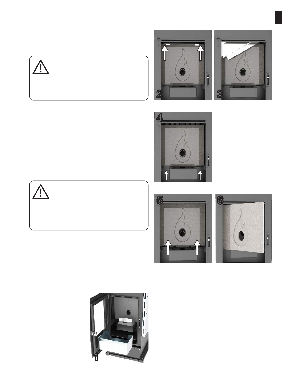
When the stove is cold,
please join the following
procedure: open the door
and pull the ash tray out and
remove the brazier. (photo 1)
Remove the mounting of
the refractory pushing it upwards and then pull it out
from the combustion chamber. (photo 2)
Turn and tilt it to remove it.
(photo 3)
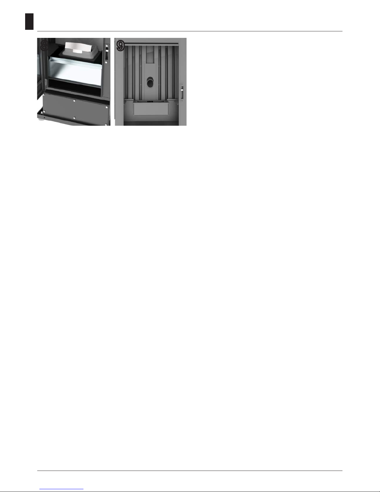
With a vacuum cleaner to clean the refractory material
and the walls of the combustion chamber, in particular the
front wall in which are located the heat exchanger pipes,
(photo 9) the bottom of the chamber combusione and the
compartment that is located below the ash box. (photo 8)
Also clean the brazier and the ash box.
After completing the cleaning, replace the refractory, its
attachment, the ash drawer and nally the brazier.
The use of aggressive detergents or thinners can damage the surfaces of the
stove.
Before using any detergent it is advisable to try it
on a small section out of sight or contact the Authorized Assistance Centre for information regarding the product.
It is necessary to daily clean the brazier
and often clean the ash box.
The lack of cleanliness can prevent the
starting of the stove, causing damages to the stove
itself and to the environment (possible emission of
unbrunt material and soot).
Do not re-use the pellet possibly remained in the
brazier due to no starting-up.
2 3
Now push the refractory upwards (photo 4 + photo 5),
rotate (photo 6) and remove
it from the combustion
chamber.
When handling the refractory take care not to break
it, it is very fragile.
4
5 6
Cleaning the surfaces
To clean the surfaces, use a rag dampened with water or
with water and a neutral detergent.
48
GB
9
8
Cleaning the clearing system
Until a reasonable experience is acquired regarding the
operating conditions, it is advisable to perform this maintenance on at least a monthly basis.
• remove the electrical feed cable;
• remove the cap from the T-joint and proceed with the
cleaning of the ducts. If necessary, at least for the rst few
times, call in qualied personnel;
• carefully clean the smoke discharge system: for this,
contact a professional chimney sweep;
• once a year clean the dust, cobwebs, etc. from the zone
behind the internal covering panels, paying particular attention to the fans.
Cleaning the fans
The stove is furnished with fans (environmental and
smoke) positioned at the rear and below the stove.
Eventual deposits of dust or ash on the blades of the fan
can cause an imbalance in the fans leading to noisy performance. It is, therefore, necessary to clean the fans at
least once a year.
Since said operation requires dismantling several parts of
the stove, have the fans cleaned only by our Technical Assistance Centre.
Season end cleaning
At the end of the season, when the stove will not be used
for some time, it is advisable to perform a thorough and
general cleaning:
• Remove all the pellets from the container and the screw
feeder;
• Carefully clean the brazier, the brazier support, the combustion chamber and the ash box.
Once the preceding points have been observed, it only
means that the state of the stove has been veried.
It is necessary to thoroughly clean the smoke discharge
tube or ue and check the condition of the basket. If necessary, order a new one from our Authorized Assistance
Centre.
If necessary, lubricate the hinges of the door and the han-
dle.
Also check the ceramic bre cord near the glass, on the
internal wall of the door; if it is worn or too dry, order a new
one from the Authorized Assistance Centre.

49
GB
Every 1200 hours of work the electronic board sends a warning signal and the display will show
“SERVICE”. This indicates the need for a thorough cleaning of the stove by a CAT. The lack of such
cleaning could result in failure of the stove and poor combustion, thereby resulting in a lower yield.
Maintenance and cleaning
Parts Everyday
Every 2-3
days
Every
week
Every 15
days
Every 30
days
Every 60-
90 days
Every year /
1200-1400 h
Brazier ◊
Cleaning ash collection compartment ◊
Cleaning ash tray ◊
Cleaning the door and glass ◊
Cleaning the interior heat exchanger /
smoke fan compartment
•
Cleaning complete exchanger •
Clean "T" to exhaust •
Flue •
Door gasket ash •
Internal parts •
Flue pipe •
Electromechanical components •
All cleaning of all parts must be carried out with the stove completely cold and unplugged to
avoid burns and thermal shock. The stove does not need much maintenance if used with certified
quality pellet. The need for maintenance varies depending on the conditions of use (switching on
and off repeatedly) and depending on the performance required.
◊ by the user
• by the authorised qualied technical assistance

50
GB
Safety devices
Pressure switch: monitors
depression in the smoke duct.
It is designed to shut down the
pellet feed screw in the event
of an obstructed ue or signicant back-pressure in the
presence of wind. At the time
of the pressure switch will
show “ALAR-DEP-FAIL”.
Pellets temperature safety:
In the rare event there is a too
high temperature in the tank,
the thermostat for pellets safety with manual reset creates an
alarm “ALAR-SIC-FAIL” stopping the pellet boiler stove.
You need to reset the system
working on the device placed
on the back of the stove.
RESTART
PELLET
Reduction motor: if the motor
stops, the stove continues to
function until the ame goes
out for lack of fuel, and until It
has cooled down to the mini-
mum level.
Flue gas temperature sensor: thermocouple that meas-
ures the temperature of the
fumes while keeping the operation or shuts the stove when
the ue gas temperature drops
below the preset value.
Electrical safety: the stove is
protected against violent surg-
es of current (ex. lightnings)
by the main fuse 4 A which is
located on the control panel
at the rear of the stove. Other
fuses to protect the electronic
boards are to be found on the
boards themselves.
Tampering with the safety devices is prohibited. It is only after eliminating the cause which gave
rise to the intervention of the safety system, that it is possible to relight the stove and thus reset
the automatic operation of the sensor. To understand which anomaly has occurred, consult this
manual at paragraph relating to alarms which explains what to do based on the alarm message the
stove display.
Room thermostat: the room
thermostat detects the present temperature in the room.
When it detects the set temperature on the display, the
stove will go into operation in
ECO ie hold function to save
fuel.
The room thermostat should
be spread so as not to be conditioned by the temperature of
the body stove.

51
GB
Any inconvenience and solutions
Given that all stoves are tested in their parts handling and work and therefore are delivered in perfect physical condition and operation, it should be remembered that the transport, unloading, handling, misuse or poor maintenance,
can be causes of drawbacks.
The main problems may be solved by reading the table below.
If after doing as hereinafter described the problem is not resolved, contact your authorized service center.
Problems and solutions
All repairs must be carried out exclusively by a specialised technician, with the stove completely
cold and the electric plug pulled out
. Is prohibited from any unauthorized modification to the
device and the replacement of parts with other non-original.
The operations marked in bold type
must be carried out by specialised personnel.
PROBLEM POSSIBLE CAUSE REMEDY
Display off and but-
tons are not working
1. Power failure in the network
2. Switch back off
3. Display defective
4. Fault in the connection of the
display with the card
5. Fuse board interrupted
6. Card defective
1. Check that the power cord is connected
2. Use the switch back to operate it
3. Unplug the stove from the power outlet for about
one minute and then turn on. If the problem persists,
contact an authorized service center
4. Check that the display and board are properly connected. Contact your authorized service
center
5. Contact an authorized service center
6. Contact an authorized service center
Remote inefcient
1. Too far from the stove
2. No batteries in the remote
3. The remote control is broken
1. Move closer to the stove
2. Check and change the batteries
3. Replace the remote control
Failure to ignite
the stove
1. Excessive accumulation of ash
in the grate
2. Incorrect ignition procedure
1. Clean the grate
2. Repeat the ignition procedure. If the problem
persists, contact your authorized service center
Smoke comes from
the grill
1. Accidental electrical blackout
1. In case of ignition phase interrupted and momentary interruption of the fan, can occur slight amount
of smoke
Hot air fan is not
working
1. The stove has not yet been
heated
1. Wait until the conclusion of the ignition cycle.
Arrived in temperature, the fan will start automatically.
If the problem persists, contact your authorized ser-
vice center.

52
GB
The stove does not
turn on automatically
1. The tank is empty.
2. The resistance does not reach
the temperature
3. Resistance damaged
4. The pellet drops
5. Screw motor defective
6. The grate is not in place or is
dirty
7. Obstruction of nests or foreign
bodies in the chimney or re-
place
8. Check operation of the glow
plug
9. The ash drawer is not closed
properly
10. Clogged ue and chimney
11. Smoke extractor not working
12. Temperature sensor defective
13. Pellet wet
1. Fill the tank with pellets
2. Check the electrical wiring and fuses, replace if
the resistance is broken
3. Replace the resistance
4. It is recommended to unplug the power supply
before:
- check that the pellet is not caught in the chute
- check that the cochlea is not blocked by dirt
- check the seal of the pellet-door
5. Contact an authorized service center
6. Check that the hole in the brazier matches the
glow plug, clean brazier
7. Remove any foreign body from the chimney or ue
pipe
8. Make sure that there is power. Replace the spark
plug if burned
9. Close the drawer ashtray
10. Perform periodic cleaning
11. Check the operation of the extractor flue
12. Contact an authorized service center
13. Make sure the place of stowage pellet and replace it with a handful of dry pellets
Lock the stove.
Pellets not being fed
into the combustion
chamber
1. The tank is empty
2. The cochlea is no pellet
3. Technical problem of the
cochlea
4. Reduction motor failure
5. Electronic board faulty
1. Load the pellets in the tank.
2. Fill the tank and proceed as instructed before igni-
tion stove
3. IT IS RECOMMENDED to unplug the power supply before:
- empty the thank and manually free the auger from
obstructions (sawdust)
- release the slide from obstructions
- remove the dust accumulation of pellets in the bottom of the tank
4. Replace the reduction motor
5. Replace the electronic board
The stove runs for a
few minutes and then
turn off
1. Lighting cycle not completed
2. Temporary failure of electricity
3. Probes fumes defective or
broken or not inserted
1. Re-run power
2. Re-run power
3. Check and replace sensors
Fume extraction fan
does not stop
1. The stove has not yet cooled
1. Allow the stove to cool. Only after cooling fan will
stop. If the problem persists, contact your authorized service center

53
GB
The stove is clogged
early in the brazier
with burning irregular,
door glass gets dirty,
the ame is long, reddish and weak
1. Flue with presence of stretch-
es too long or clogged
2. Too pellet
3. Excessive pellet or ash deposits in the brazier
4. The brazier is not found in its
slot
5. Wind contrary to the exhaust
ow
6. Insufcient combustion air
7. You changed the type of pel-
lets used
8. Smoke extractor motor broken
9. Door closed incorrectly
1. Perform periodic cleaning. See paragraph stove
installation in the user manual. Check chimney
cleaning
2. Decrease in the parameters the charge level of the
pellets
3. Clean the brazier after waiting for the total shutdown of the stove. If you repeat contact your
Authorized Service Center
4. Check that the hole in the brazier matches the
glow plug
5. Check the chimney cap windproof and / or possibly install it
6. Check the correct position of the brazier, its cleanliness and check that the air intake in both free environment, verify the status of the door seal, increase
the level in the parameter relative to the speed of
the fan exhaust fumes. Contact your Authorized
Service Center
7. Check the quality of the pellets. Contact your
Authorized Service Center
8. Increase the level in the parameters relating to the
speed of the fan exhaust fumes. Check and eventu-
ally replace motor
9. Check that the glass is sealed and the seal guarantees tightness
Smell of smoke in the
environment. Turning
off the stove.
1. Poor combustion
2. Malfunction of fan fumes
3. Installation of the ue performed incorrectly
4. Clogged chimney
1. Contact your Authorized Service Center
2. Contact your Authorized Service Center
3. Contact your Authorized Service Center
4. Contact your Authorized Service Center
In the automatic position the stove always
runs at full power
1. Room thermostat set to maxi-
mum
2. Signicant temperature sensor
failure
3. Control panel defective or
broken
1. Reset the thermostat temperature
2. Check the operation of the sensor and replace if
necessary
3. Check the control panel and replace if necessary
The engine smoke
extraction does not
work
1. The stove has no voltage
2. The motor is broken
3. The board is defective
4. The control panel has failed
1. Check the supply voltage and the protection fuse.
2. Check the motor and capacitor and replace if
necessary.
3. Replace the circuit board.
4. Replace the control panel.

54
GB
The manufacturer of the stove any liability and will void the warranty terms of the product for any
inconvenience caused by not following the rules described above. Any work of service center will
be borne by the applicant if they are not complied with these instructions.
The re goes out or
the stove stops automatically
1. The pellet tank is empty
2. No power
3. Pellets not being fed
4. Excessive deposit of ashes in
the grate
5. Intervention probe temperature
safety of the pellet
6. Cochlea blocked by dirt
7. The door is not closed properly or gaskets worn
8. Pellet inadequate
9. Low pellet
10. Chimney or drain clogged
with nests or foreign bodies
11. Pressure switch cuts
12. Smoke extraction motor
failure
13. Alarm active
1. Fill the tank with pellets
2. Check plug and presence electricity
3. Fill the tank with pellets
4. Clean the brazier
5. Let the stove cool down completely, reset the
manual reset and restart the stove. If the problem
persists, contact your authorized service representa-
tive
6. Pull the plug, empty the tank, remove any foreign
objects
7. Close the door or replace the gaskets with original
8. Change the type of pellet recommended by the
manufacturer. Sometimes, depending on the type,
the stage of adjustment of the parameters need
to vary the level relating to the loading of pellets
9. Increase the level in the parameter for the pellet feed. To check the flow of fuel from technical
authorized
10. Eliminate all foreign matter from the chimney
Clean the smoke duct. Perform periodic cleaning.
11. Verify potential smoke duct is blocked and if
the pressure switch is working properly
12. Check and replace the motor if necessary
13. See paragraph alarms
The air fan convention
(ambient air) never
stops
1. Temperature sensor tempera-
ture control defective or broken
2. Smoke probe fails
1. Check the operation of the sensor and replace if
necessary
2. Replace smoke probe
The stove does not
light.
1. Lack of electricity
2. Probe pellets in bulk
3. Fuse blown
4. Pressure switch broken (lockout indicated)
5. Smoke outlet or duct clogged
1. Check that the electrical outlet is plugged in and
the power switch to "I"
2. Lockout by resetting the rear thermostat, replace
the thermostat if it happens again
3. Replace the fuse
4. Replace the pressure
5. Clean the smoke outlet and / or smoke duct

55
GB
NOTES

56
GB
NOTES
 Loading...