


J
REVISION
This information is subject to the controls of the Export Administration
High Current Density Plasma Cutting System
with
Automatic Gas Console
User’s Manual - Part Number 718086 Rev J
10/15/2012
Regulations [EAR]. This information shall not be provided to non-U.S.
persons or transferred by any means to any location outside the United
States contrary to the requirements of the EAR.

Spirit200a User’s Manual Rev J
Rev
ECO#
Author
Date
Description of Change
A -
As released
B -
05/08/07
Changed location of coolant level switch
Changed 30A mild steel preflow pressure from 30 to 35
psi
Changed 575V control xfmr part number to 706205
Added PAR relay in series with surge injection circuit to
schematic and parts list
Section Updates:
Section 8
Section Updates:
Appendix B - deleted
Section Updates:
Postflow label changed in 8-9
• Section1, added pointers to Section 7.
microprocessor board.
Section 7, defective flow switch (25 blinks).
REVISION HISTORY
C - 05/23//07
• Changed cutting charts to have separate metric and
D - 07/02/07
E - 10/15/07
F - 10/21/09
G - 10/25/10
imperial versions.
•
• Contents
• Section 2
• Section 3
• Section 7
•
• Contents
• Section 3
• Section 4
• Section 5
• Section 6
• Section 7
• Section 8
• Appendix A
•
H 05/10/2011
I 08/01/2012
J 10/15/2012
This documentation may not be copied, photocopied, reproduced, translated, or reduced to
any electronic medium or machine-readable format without explicit written permission from
This information is subject to the controls of the Export Administration Regulations [EAR]. This information shall not be provided to
non-U.S. persons or transferred by any means to any location outside the United States contrary to the requirements of the EAR.
• Max Input Pressure changed to 145 psi in: 2-4, 3-1,
3-13, 3-14, 8-8
• AGC fan added to drawings in: 3-1, 3-13
•
• Section 4, corrected cut chart for
Aluminum/70amp/Air Plasma/Nitro Shield.
• Section 7, added chopper warning.
• Section 8, updated drawing of power supply
• Added Quick-Disconnect Torch information
throughout manual.
•
Kaliburn.
4130 Carolina Commerce Parkway
Ladson, SC 29456 USA
(843) 695-4000 - Phone
(843) 695-4001 - Fax
www.kaliburn.net

Spirit200a User’s Manual Rev J
LIMITED WARRANTY
KALIBURN expressly warrants that this product shall be free from defects in materials
and workmanship, under proper and normal use for the intended function of such
equipment, for a period of one (1) year for the Spirit200a torch and leads and three (3)
years for the Spirit200a power supply and automatic gas console. This product is
intended for commercial use and is not intended for personal, family, or household
purposes. There are no warranties that extend beyond the description on the face
hereof. All other warranties, either expressed or implied, including any implied
warranty of merchantability or fitness for any particular purpose, are expressly
excluded.
If this product or any component thereof is determined to be defective in manufacture,
KALIBURN will repair or replace the defective component or product. The buyer’s
remedies are limited to the return of the product for repair or replacement of any nonconforming product or part at the sole discretion of KALIBURN. No freight charges of
any kind are covered under this warranty. All returned goods shall be at the buyer’s risk
and expense. Beyond this remedy, KALIBURN will not be responsible for any special,
incidental or consequential damages or injury to the person or property of anyone by
reason of any defect in any equipment sold hereunder.
This warranty will be considered void if torches or
torch consumables manufactured by anyone other
than KALIBURN are incorporated into this product.
RETURNED GOODS PROCEDURE
KALIBURN utilizes a returned goods procedure that must be followed before returning
any items for repair, replacement, or restocking. This means that a returned goods
authorization number must be obtained prior to shipment to KALIBURN. It will be
necessary for the customer to provide a description, along with the stock number and
serial number, if applicable, of the item to be returned. In no case will KALIBURN
accept a returned shipment without the proper returned goods authorization number.
For shipments inside the U.S., parts must be returned to KALIBURN within 30 days of
the invoice date to be considered for credit. For shipments outside the U.S., parts must
be returned within 60 days of the invoice date to be considered for credit.
ELECTROMAGNETIC COMPATIBILITY (EMC)
The 380V 50/60Hz and 415V 50/60Hz CE marked Spirit200a plasma cutting systems
are manufactured to comply with the European standard EN 60974-10 (Electromagnetic
compatibility (EMC) – Product standard for arc welding equipment). Information about
the EMC standard EN 60974-10 can be found in Appendix A.
This information is subject to the controls of the Export Administration Regulations [EAR]. This information shall not be provided to
non-U.S. persons or transferred by any means to any location outside the United States contrary to the requirements of the EAR.

Spirit200a User’s Manual Rev J
TABLE OF CONTENTS
Section 1 Safety
General Precautions ............................................................................................... 1-1
Ultraviolet Radiation Protection ............................................................................... 1-1
Noise Protection ...................................................................................................... 1-1
Toxic Fume Prevention ........................................................................................... 1-1
Electric Shock Prevention ....................................................................................... 1-2
Fire Prevention ........................................................................................................ 1-3
Explosion Prevention .............................................................................................. 1-3
Health Support Equipment ...................................................................................... 1-4
Safety Standards Booklet Index .............................................................................. 1-5
Section 2 Specifications
System Description ................................................................................................. 2-1
System Components ............................................................................................... 2-2
Power Supply Specifications ................................................................................... 2-3
Automatic Gas Console Specifications ................................................................... 2-5
Remote High Frequency Console Specifications .................................................... 2-6
Torch Specifications ................................................................................................ 2-7
5-Gang Manifold Specifications .............................................................................. 2-8
Airborne Noise Emissions ....................................................................................... 2-9
Section 3 Installation
Initial Inspection ...................................................................................................... 3-1
System Interconnection .......................................................................................... 3-1
Power Supply Installation ........................................................................................ 3-2
Remote High Frequency Installation ....................................................................... 3-2
5-Gang Manifold Installation ................................................................................... 3-2
Torch Installation ..................................................................................................... 3-2
Primary Power Connection ..................................................................................... 3-3
Power Supply Output Connections ......................................................................... 3-5
RHF Console Ground Connection .......................................................................... 3-6
Torch Leads to RHF Console Connections ............................................................ 3-8
Torch Leads to Torch Base Connections................................................................. 3-10
Torch Gas Connections .......................................................................................... 3-11
Torch Head Connection .......................................................................................... 3-14
Automatic Gas Console Input Connections ............................................................ 3-15
CNC Machine Interface Connections ...................................................................... 3-16
Torch Coolant Requirements .................................................................................. 3-18
Initial Filling of the Torch Coolant Reservoir............................................................ 3-19
This information is subject to the controls of the Export Administration Regulations [EAR]. This information shall not be provided to
non-U.S. persons or transferred by any means to any location outside the United States contrary to the requirements of the EAR.

Spirit200a User’s Manual Rev J
Section 4 Operation
Power Supply Front Panel Controls ........................................................................ 4-1
Automatic Gas Console Keypad ............................................................................. 4-3
Automatic Gas Console Help Prompt ..................................................................... 4-4
Automatic Gas Console Status Screen ................................................................... 4-5
Setting up a Cut or Mark ......................................................................................... 4-6
Torch Consumable Selection .................................................................................. 4-11
Installing or Removing Torch Consumables............................................................ 4-18
Making a Cut or Mark .............................................................................................. 4-19
Piercing Thick Materials…………………………………………………………..…….. 4-20
Cut Quality .............................................................................................................. 4-21
Changing Consumable Parts .................................................................................. 4-22
Consumable Life ..................................................................................................... 4-23
Cutting Charts ......................................................................................................... 4-24
Section 5 Automatic Gas Console Advanced Functions
Altering the Current Set Point ................................................................................. 5-1
Setting the Pierce Time .......................................................................................... 5-2
Altering Gas Types ................................................................................................. 5-3
Altering Gas Pressures ........................................................................................... 5-4
Altering Arc Voltage Control and X/Y Machine Parameters .................................... 5-5
Saving a User Created Cutting or Marking Condition ............................................. 5-6
Gas Purge ............................................................................................................... 5-6
Maintenance Screen ............................................................................................... 5-7
Viewing Messages .................................................................................................. 5-8
Viewing Cut Errors .................................................................................................. 5-9
Pressure Diagnostics .............................................................................................. 5-12
Restoring Factory Default Cutting or Marking Conditions ....................................... 5-13
Measurement System ............................................................................................. 5-14
Communication Node ............................................................................................. 5-15
Inova Parameter Transmit ...................................................................................... 5-16
Viewing Serial Communication ............................................................................... 5-17
Configuring Hydrogen Cutting ................................................................................. 5-18
Setting an Arc Off Delay ......................................................................................... 5-19
Switching Between Cutting and Marking ................................................................ 5-20
Software Updates ................................................................................................... 5-21
Section 6 Serial Communication
Initializing the Spirit System .................................................................................... 6-1
Transmitting Parameters to the Spirit System ........................................................ 6-1
Communication Error Checking .............................................................................. 6-2
Default Cutting Parameters ..................................................................................... 6-3
Troubleshooting Serial Communication .................................................................. 6-3
RS-422 Serial Commands ...................................................................................... 6-4
This information is subject to the controls of the Export Administration Regulations [EAR]. This information shall not be provided to
non-U.S. persons or transferred by any means to any location outside the United States contrary to the requirements of the EAR.

Spirit200a User’s Manual Rev J
Section 7 Maintenance and Troubleshooting
Routine Maintenance .............................................................................................. 7-1
Replacing the Torch Coolant .................................................................................. 7-4
Microprocessor Status LED’s .................................................................................. 7-5
Microprocessor Sequence of Operation ................................................................. 7-6
Troubleshooting Using the Control Panel Status LED’s ......................................... 7-7
Troubleshooting Using the Automatic Gas Console Messages Screen ................. 7-8
General Troubleshooting ........................................................................................ 7-9
Chopper Test Procedure ......................................................................................... 7-12
Section 8 Parts List
Power Supply .......................................................................................................... 8-1
Automatic Gas Console .......................................................................................... 8-7
Remote High Frequency Console ........................................................................... 8-10
Torch and Manifold Assemblies .............................................................................. 8-11
Shielded Torch Leads ............................................................................................. 8-12
Gas Hose Package ................................................................................................. 8-13
Coolant and Power Leads ....................................................................................... 8-14
Work Ground Cable ................................................................................................ 8-15
Oxygen Supply Gas Hose (Optional) ...................................................................... 8-16
Nitrogen Supply Gas Hose (Optional) ..................................................................... 8-16
Air Supply Gas Hose (Optional) .............................................................................. 8-16
H17 Supply Gas Hose (Optional) ............................................................................ 8-16
Power Supply Microprocessor P.C. Board .............................................................. 8-17
A.C. Detect P.C. Board ........................................................................................... 8-18
Relay P.C. Board .................................................................................................... 8-19
Power Supply I/O P.C. Board ................................................................................. 8-20
Automatic Gas Console I/O P.C. Board .................................................................. 8-21
Consumable Spare Parts Kit ................................................................................... 8-22
Appendix A Electromagnetic Compatibility (EMC)
Background ............................................................................................................. A-1
Installation and Use ................................................................................................ A-1
Assessment of Area ................................................................................................ A-2
Methods of Reducing Emissions ............................................................................. A-2
This information is subject to the controls of the Export Administration Regulations [EAR]. This information shall not be provided to
non-U.S. persons or transferred by any means to any location outside the United States contrary to the requirements of the EAR.

Safety Spirit200a User’s Manual Rev J
This information is subject to the controls of the Export Administration Regulations [EAR]. This information shall not be provided to
non-U.S. persons or transferred by any means to any location outside the United States contrary to the requirements of the EAR.
1-1
Section 1 Safety
General Precautions
Whereas plasma cutting has been used safely for years, it does require
certain precautions to ensure the safety of the operator and other people
around the equipment. The following safety information must be provided
to each person who will operate, observe, perform maintenance, or work
in close proximity to this piece of equipment.
Installation, operation, and repairs made to the Spirit200a system should
only be performed by qualified personnel. The Spirit system makes use of
both A.C. and D.C. circuitry for operation. Fatal shock hazard does
exist. Exercise extreme caution while working on the system.
Ultraviolet Radiation Protection
Plasma cutting produces ultraviolet radiation similar to a welding arc. This
ultraviolet radiation can cause skin and eye burns. For this reason, it is
essential that proper protection be worn. The eyes are best protected by
using safety glasses or a welding helmet with an AWS No. 12 shade or
ISO 4850 No. 13 shade, which provides protection up to 400 amperes. All
exposed skin areas should be covered with flame-retardant clothing. The
cutting area should also be prepared in such a way that ultraviolet light
does not reflect. Walls and other surfaces should be painted with dark
colors to reduce reflected light. Protective screens or curtains should be
installed to protect additional workers in the area from ultraviolet radiation.
Noise Protection
The Spirit200a system generates high noise levels while cutting.
Depending on the size of the cutting area, distance from the cutting torch,
and arc current cutting level, acceptable noise levels may be exceeded.
Proper ear protection should be used as defined by local or national
codes. See Section 2 for noise emission levels.
Toxic Fume Prevention
Care should be taken to ensure adequate ventilation in the cutting area.
Some materials give off toxic fumes that can be harmful or fatal to people
in the vicinity of the cutting area. Also, some solvents decompose and

Safety Spirit200a User’s Manual Rev J
This information is subject to the controls of the Export Administration Regulations [EAR]. This information shall not be provided to
non-U.S. persons or transferred by any means to any location outside the United States contrary to the requirements of the EAR.
1-2
form harmful gases when exposed to ultraviolet radiation. These solvents
should be removed from the area prior to cutting.
Galvanized metal can produce harmful gases during the cutting process.
Ensure proper ventilation and use breathing equipment when cutting these
materials.
Certain metals coated with or containing lead, cadmium, zinc, beryllium,
and mercury produce harmful toxins. Do not cut these metals unless all
people subjected to the fumes wear proper air breathing equipment.
Electric Shock Prevention
The Spirit200a system uses high open circuit voltages that can be fatal.
Extreme care should be used when operating or performing maintenance
on the system. Only qualified personnel should service the Spirit system.
Observe the following guidelines to protect against electric shock:
• A wall-mounted disconnect switch should be installed and fused
according to local and national electrical codes. The disconnect switch
should be located as close as possible to the power supply so it can be
turned off in case of an emergency.
• The primary power cord should have a 600 volt minimum rating in
order to protect the operator. In addition, it should be sized according
to local and national electrical codes. Inspect the primary power cord
frequently. Never operate the Spirit system if the power cord is
damaged in any way.
• Make sure the primary power ground wire is connected to the input
power ground stud on the Spirit power supply. Make sure the
connection is securely tightened.
• Make sure the positive output (work ground) of the Spirit power supply
is connected to a bare metal area on the cutting table. A driven ground
rod should be placed no further than five feet from this connection.
Make sure this ground point on the cutting table is used as the star
ground point for all other ground connections.
• Inspect the torch leads frequently. Never use the system if the leads
are damaged in any way.
• Do not stand in wet, damp areas when operating or performing
maintenance on the system.
• Wear insulated gloves and shoes while operating or performing
maintenance on the system.
• Make sure the Spirit system is switched off at the wall disconnect
before servicing the power supply or torch.
• Never change torch consumable parts unless the Spirit system is
switched off at the wall disconnect.

Safety Spirit200a User’s Manual Rev J
This information is subject to the controls of the Export Administration Regulations [EAR]. This information shall not be provided to
non-U.S. persons or transferred by any means to any location outside the United States contrary to the requirements of the EAR.
1-3
• Do not attempt to remove any parts from beneath the torch when
cutting. Remember that the workpiece forms the current path back to
the power supply.
• Never bypass the safety interlock devices.
• Before removing any of the Spirit covers, switch the system off at the
wall disconnect. Wait at least five (5) minutes before removing any
cover. This will give the capacitors inside the unit time to discharge.
See Section 7 for additional safety precautions.
• Never operate the Spirit system without all of the covers in place. See
Section 7 for additional safety precautions.
• Preventive maintenance should be performed daily to avoid possible
safety hazards.
Fire Prevention
When using the Spirit200a system, it is necessary to exercise good
judgment. While cutting, the arc produces sparks that could cause a fire if
they fall on flammable materials. Make sure that all flammable materials
are a suitable distance away from the cutting area. All flammable liquids
should be at least 40 feet away from the cutting area, preferably stored in
a metal cabinet. Plasma cutting should never be attempted on containers
that contain flammable materials. Make sure that fire extinguishers are
readily accessible in the cutting area.
Make sure that the cutting area is properly ventilated when using oxygen
as a cutting gas.
Explosion Prevention
The Spirit200a system uses compressed gases. Use proper techniques
when handling compressed gas cylinders and other compressed gas
equipment. Observe the following guidelines to protect against explosion:
• Never operate the Spirit system in the presence of explosive gases or
other explosive materials.
• Never cut pressurized cylinders or any closed container.
• When using a water table and cutting aluminum under water or with
water touching the underside of the aluminum plate, hydrogen gas is
produced. This hydrogen gas may collect under the plate and explode
during the cutting process. Make sure the water table is properly
aerated to help prevent the accumulation of hydrogen gas.
• Handle all gas cylinders in accordance with safety standards published
by the U.S. Compressed Gas Association (CGA), American Welding
Society (AWS), Canadian Standards Association (CSA), or other local
or national codes.

Safety Spirit200a User’s Manual Rev J
This information is subject to the controls of the Export Administration Regulations [EAR]. This information shall not be provided to
non-U.S. persons or transferred by any means to any location outside the United States contrary to the requirements of the EAR.
1-4
• Compressed gas cylinders should be maintained properly. Never
attempt to use a cylinder that is leaking, cracked, or has other signs of
physical damage.
• All gas cylinders should be secured to a wall or rack to prevent
accidental knock over.
• If a compressed gas cylinder is not being used, replace the protective
valve cover.
• Never attempt to repair compressed gas cylinders.
• Keep compressed gas cylinders away from intense heat, sparks, or
flames.
• Clear the compressed gas cylinder connection point by opening the
valve momentarily prior to installing a regulator.
• Never lubricate compressed gas cylinder valves or pressure regulators
with any type of oil or grease.
• Never use a compressed gas cylinder or pressure regulator for any
purpose other than which it is intended.
• Never use a pressure regulator for any gas other than which it is
intended.
• Never use a pressure regulator that is leaking or has other signs of
physical damage.
• Never use oxygen hoses and pressure regulators for any gas other
than oxygen.
• Never use any gas hose that is leaking or has other signs of physical
damage.
Health Support Equipment
The Spirit200a system creates electric and magnetic fields that may
interfere with certain types of health support equipment, such as
pacemakers. Any person who uses a pacemaker or similar item should
consult a doctor before operating, observing, maintaining, or servicing the
Spirit system. Observe the following guidelines to minimize exposure to
these electric and magnetic fields:
• Stay as far away from the Spirit power supply, torch, torch leads, and
remote high frequency console as possible.
• Route the torch leads as close as possible to the work ground cable.
• Never place your body between the torch leads and work ground
cable. Keep the work ground cable and the torch leads on the same
side of your body.
• Never stand in the center of a coiled up set of torch leads or work
ground cable.

Safety Spirit200a User’s Manual Rev J
This information is subject to the controls of the Export Administration Regulations [EAR]. This information shall not be provided to
non-U.S. persons or transferred by any means to any location outside the United States contrary to the requirements of the EAR.
1-5
Safety Standards Booklet Index
For further information concerning safety practices to be exercised with
plasma arc cutting equipment, please refer to the following publications:
1. AWS Standard AWN, Arc Welding and Cutting Noise, obtainable from
the American Welding Society, 550 NW LeJeune Road, Miami, FL
33126.
2. AWS Standard C5.2, Recommended Practices for Plasma Arc
Cutting, obtainable from the American Welding Society, 550 NW
LeJeune Road, Miami, FL 33126.
3. AWS Standard FSW, Fire Safety in Welding and Cutting, obtainable
from the American Welding Society, 550 NW LeJeune Road, Miami,
FL 33126.
4. AWS Standard F4.1, Recommended Safe Practices for Preparation
for Welding and Cutting of Containers and Piping, obtainable from the
American Welding Society, 550 NW LeJeune Road, Miami, FL 33126.
5. AWS Standard ULR, Ultraviolet Reflectance of Paint, obtainable from
the American Welding Society, 550 NW LeJeune Road, Miami, FL
33126.
6. AWS / ANSI Standard Z49.1, Safety in Welding, Cutting, and Allied
Processes, obtainable from the American Welding Society, 550 NW
LeJeune Road, Miami, FL 33126.
7. ANSI Standard Z41.1, Standard For Men’s Safety-Toe Footwear,
obtainable from the American National Standards Institute, 11 West
42nd Street, New York, NY 10036.
8. ANSI Standard Z49.2, Fire Prevention in the Use of Cutting and
Welding Processes, obtainable from the American National Standards
Institute, 11 West 42nd Street, New York, NY 10036.
9. ANSI Standard Z87.1, Safe Practices For Occupation and Educational
Eye and Face Protection, obtainable from the American National
Standards Institute, 11 West 42nd Street, New York, NY 10036.
10. ANSI Standard Z88.2, Respiratory Protection, obtainable from the
American National Standards Institute, 11 West 42nd Street, New
York, NY 10036.

Safety Spirit200a User’s Manual Rev J
This information is subject to the controls of the Export Administration Regulations [EAR]. This information shall not be provided to
non-U.S. persons or transferred by any means to any location outside the United States contrary to the requirements of the EAR.
1-6
11. OSHA Standard 29CFR 1910.252, Safety and Health Standards,
obtainable from the U.S. Government Printing Office, Washington,
D.C. 20402.
12. NFPA Standard 51, Oxygen - Fuel Gas Systems for Welding, Cutting,
and Allied Processes, obtainable from the National Fire Protection
Association, 1 Batterymarch Park, Quincy, MA 02269.
13. NFPA Standard 51B, Cutting and Welding Processes, obtainable from
the National Fire Protection Association, 1 Batterymarch Park, Quincy,
MA 02269.
14. NFPA Standard 70, National Electrical Code, obtainable from the
National Fire Protection Association, 1 Batterymarch Park, Quincy,
MA 02269.
15. CGA booklet P-1, Safe Handling of Compressed Gases in Containers,
obtainable from the Compressed Gas Association, 1725 Jefferson
Davis Highway, Suite 1004, Arlington, VA 22202.
16. CGA booklet P-14, Accident Prevention in Oxygen-Rich and Oxygen-
Deficient Atmospheres, obtainable from the Compressed Gas
Association, 1725 Jefferson Davis Highway, Suite 1004, Arlington, VA
22202.
17. CGA booklet TB-3, Hose Line Flashback Arrestors, obtainable from
the Compressed Gas Association, 1725 Jefferson Davis Highway,
Suite 1004, Arlington, VA 22202.
18. CSA Standard W117.2, Safety in Welding, Cutting, and Allied
Processes, obtainable from Canadian Standards Association, 178
Rexdale Boulevard, Toronto, Ontario M9W lR3, Canada.
19. Canadian Electrical Code Part 1, Safety Standard for Electrical
Installations, obtainable from the Canadian Standards Association,
178 Rexdale Boulevard, Toronto, Ontario M9W 1R3, Canada.

Specifications Spirit200a User’s Manual Rev J
This information is subject to the controls of the Export Administration Regulations [EAR]. This information shall not be provided to
non-U.S. persons or transferred by any means to any location outside the United States contrary to the requirements of the EAR.
2-1
Section 2 Specifications
System Description
The Spirit200a is a 200 amp microprocessor controlled, 100% duty cycle
high current density plasma cutting and marking system. It utilizes a
precision, dual gas torch that is capable of cutting mild steel up to 2" thick
and stainless steel up to 1-1/2” thick. The Spirit200a is equipped with a
computer controlled automatic gas console with VGA display. All cutting
parameters are controlled from the automatic gas console. Setting up a
cut is as simple as entering the material type, material thickness, and
process (cutting or marking). All gas types and pressures are set
automatically and the cutting parameters are transmitted to the Spirit
power supply. Switching to a different screen on the gas console gives
the operator a pictorial view of the torch parts required to make the cut.
Another screen shows the recommended cutting speed and torch height
for making the cut. These parameters can even be transmitted to an x/y
machine controller or an arc voltage control system via RS-422 serial
communication. The RS-422 port also allows for full control of the cutting
parameters from an x/y machine controller. The gas console also tracks
the number of cuts made with a particular set of consumables and keeps a
detailed record of errors that may occur during the cutting sequence. To
aid in troubleshooting, a message screen on the gas console displays all
power supply and gas console sequencing. All gas inlets and outlets are
connected to the rear of the automatic gas console. For cutting mild steel,
the Spirit200a uses oxygen for the plasma gas and either oxygen or air for
the shielding gas. When cutting stainless steel or other non-ferrous
materials, air or H17 (17.5% hydrogen, 32.5% argon, 50% nitrogen) is
used for the plasma gas and either air or nitrogen is used for the shielding
gas. Oxygen and nitrogen are used for the preflow and postflow gases.
The Spirit200a is technologically advanced to produce the highest quality
cuts while maximizing consumable life. The torch is water-cooled and
consumables are machined to exacting dimensions and checked with the
latest computerized measuring systems. Six nozzle sizes (30, 50, 70,
100, 150, and 200 amps) are available to produce excellent cut quality
throughout the cutting range.

Specifications Spirit200a User’s Manual Rev J
This information is subject to the controls of the Export Administration Regulations [EAR]. This information shall not be provided to
non-U.S. persons or transferred by any means to any location outside the United States contrary to the requirements of the EAR.
2-2
System Components
The degree of protection provided by the Spirit200a system is IP21S and
as such is intended only for indoor use. It is not suitable for use in rain or
snow.
The Spirit200a system is tested in accordance with CISPR 11, EMC
classification – Group 2 ISM (Class A).
The Spirit200a consists of the following components:
Standard Components
• Power Supply
• Automatic Gas Console
• Remote High Frequency (RHF) Console
• RHF Console Control Cable
• Torch and Handle Assembly
• Torch Lead Set
• 5-gang Manifold Assembly
• 5-gang Manifold Control Cable
• 2-gang Manifold Assembly
• 2-gang Manifold Control Cable
• Water and Power Leads
• Gas Hose Package
• Work Ground Lead
• System Manual
• Consumable Spare Parts Kit (see Section 8 for details)
Optional Components
• Supply Gas Hoses (see Section 8 for details)

Specifications Spirit200a User’s Manual Rev J
This information is subject to the controls of the Export Administration Regulations [EAR]. This information shall not be provided to
non-U.S. persons or transferred by any means to any location outside the United States contrary to the requirements of the EAR.
2-3
Power Supply Specifications
Stock Number:
208 VAC, 3Ø, 60Hz ..................................... 282410
230 VAC, 3Ø, 60Hz ..................................... 282411
380 VAC, 3Ø, 50/60Hz ................................ 282413
415 VAC, 3Ø, 50/60Hz ................................ 282414
460 VAC, 3Ø, 60Hz ..................................... 282412
575 VAC, 3Ø, 60Hz ..................................... 282415
Input Current at Maximum Output:
208 VAC, 3Ø, 60Hz ..................................... 115 amps
230 VAC, 3Ø, 60Hz ..................................... 104 amps
380 VAC, 3Ø, 50/60Hz ................................ 63 amps
415 VAC, 3Ø, 50/60Hz ................................ 58 amps
460 VAC, 3Ø, 60Hz ..................................... 52 amps
575 VAC, 3Ø, 60Hz ..................................... 42 amps
Open Circuit Voltage ......................................... 300 VDC
Output Current (drooping characteristic)............ 10 - 200 amps
Maximum Output Voltage ................................. 190 VDC
Duty Cycle ......................................................... 100% @ 32 kW
Maximum Ambient Temperature ....................... 104° F (40° C)
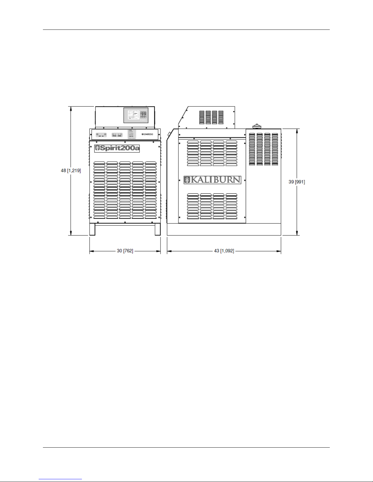
Dimensions:
Width ............................................................ 30 in (762 mm)
Height (including AGC) ................................ 48 in (1219 mm)
Depth ........................................................... 43 in (1092 mm)
Weight (including AGC) .................................... 1255 lb (569 kg)
Specifications Spirit200a User’s Manual Rev J
This information is subject to the controls of the Export Administration Regulations [EAR]. This information shall not be provided to
non-U.S. persons or transferred by any means to any location outside the United States contrary to the requirements of the EAR.
2-4
Torch Cooling System:
Discharge pressure ...................................... 150 psi (10.2 bar)
Flow rate ...................................................... 1 gal/min (3.8 liters/min)
Coolant fluid ................................................. Propylene glycol/deionized water
Coolant tank capacity ................................... 3.2 gal (12 liters)

Specifications Spirit200a User’s Manual Rev J
This information is subject to the controls of the Export Administration Regulations [EAR]. This information shall not be provided to
non-U.S. persons or transferred by any means to any location outside the United States contrary to the requirements of the EAR.
2-5
Automatic Gas Console Specifications
Stock Number ................................................... 282002
Height ................................................................ 9 in (229 mm)
Width ................................................................. 25 in (635 mm)
Depth ................................................................ 23.8 in (605 mm)
Weight ............................................................... 110 lb (50 kg)
Gas Supply Requirements
Plasma gas types:
Mild Steel ............................................... Oxygen or Air
Stainless Steel ....................................... Air or H17
Aluminum ............................................... Air
Shield gas types:
Mild Steel ............................................... Oxygen or Air
Stainless Steel ....................................... Air or Nitrogen
Aluminum ............................................... Air or Nitrogen
Preflow gas type .......................................... Oxygen and Nitrogen
Marking gas type .......................................... Nitrogen
Plasma gas flow rate (maximum):
Oxygen or Air ......................................... 67 scfh (1897 liters/hour)
H17 ......................................................... 75 scfh (2124 liters/hour)
Shield gas flow rate (maximum):
Oxygen ................................................... 19 scfh (538 liters/hour)
Air or Nitrogen ........................................ 225 scfh (6371 liters/hour)
Preflow gas flow rate (maximum) ................. 60 scfh (1699 liters/hour)
Marking gas flow rate (maximum) ................ 77 scfh (2180 liters/hour)
Rated Inlet gas pressures ....................................... 120 psi (8.3 bar)
Maximum Inlet gas pressure………………………….145 psi (10.0 bar)
Oxygen and nitrogen should be supplied with a purity of at least 99.5%.
H17 should be supplied with a purity of at least 99.995%. A potential fire
hazard exists when cutting with oxygen. KALIBURN recommends
that an exhaust ventilation system be used when cutting with
oxygen. Flashback arrestors must be supplied (unless they are not
available for the chosen gases and pressures) to prevent a possible
fire from propagating back to the gas supplies. Ensure that oxygen
lines remain free from contaminants such as oil and grease. The mixture
of such contaminants with oxygen presents an additional fire hazard.
Compressed air must be clean, dry, and oil-free and may be supplied from
compressed cylinders or from an air compressor. Be aware that shop air
systems are prone to oil and moisture contamination. If shop air is used, it
must be cleaned to ISO 8573.1: Class 1.4.1. Specify dry air when using
compressed cylinders. Breathing quality air contains moisture and must
not be used. 3/8” (inside diameter) hoses are required for all inlet gas
connections. Mating connectors are supplied with the unit.
Quick-connect fittings must not be used.

Specifications Spirit200a User’s Manual Rev J
This information is subject to the controls of the Export Administration Regulations [EAR]. This information shall not be provided to
non-U.S. persons or transferred by any means to any location outside the United States contrary to the requirements of the EAR.
2-6
Remote High Frequency Console Specifications
Stock Number ................................................... 205500
Height ................................................................ 5.35 in (136 mm)
Width ................................................................. 13.5 in (343 mm)
Depth ................................................................ 10 in (25 mm)
Weight ............................................................... 22 lb (10 kg)
Spark gap distance ........................................... .015 in (.381 mm)

Specifications Spirit200a User’s Manual Rev J
This information is subject to the controls of the Export Administration Regulations [EAR]. This information shall not be provided to
non-U.S. persons or transferred by any means to any location outside the United States contrary to the requirements of the EAR.
2-7
Torch Specifications
Stock Number:
2-Gang Manifold Assembly..................................... 260214
Torch Handle .......................................................... 820134
Torch Base ............................................................. 279050
Torch Head (Copper Electrode) .............................. 279150
Torch Head (Silver Electrode) ................................ 279160
Weight:
Manifold/Bracket, Handle, Base and Head ............. 7.3 lbs (3.3 kg)
Torch Handle
9.20 [234]
1.99
[51]
Torch Head
5.08 [129]
Torch Base
1.87 [47]
Manifold
3.38 [86]
Alignment Indicator
(Small Circle)
Attachment Ring
Alignment Indicator
(Slot)

Specifications Spirit200a User’s Manual Rev J
This information is subject to the controls of the Export Administration Regulations [EAR]. This information shall not be provided to
non-U.S. persons or transferred by any means to any location outside the United States contrary to the requirements of the EAR.
2-8
5-Gang Manifold Specifications
Stock Number ................................................... 280022
Height ................................................................ 3.035 in (77 mm)
Width ................................................................. 8.35 in (212 mm)
Depth ................................................................ 7 in (178 mm)
Weight ............................................................... 6 lb (2.7 kg)

Specifications Spirit200a User’s Manual Rev J
This information is subject to the controls of the Export Administration Regulations [EAR]. This information shall not be provided to
non-U.S. persons or transferred by any means to any location outside the United States contrary to the requirements of the EAR.
2-9
Airborne Noise Emissions
The Spirit200a system generates high noise levels while cutting.
Depending on the size of the cutting area, distance from the cutting torch,
and arc current cutting level, acceptable noise levels may be exceeded.
Proper ear protection should be used as defined by local or national
codes. The following chart gives the noise levels generated by the
Spirit200a when operating at 200 amps, 135 arc volts. The
measurements were made with a sound level meter.
Distance From Torch
A-Weighted Sound
Pressure Level
C-Weighted Sound
Pressure Level
1 meter horizontal / 1.6
meters above the
workpiece
110 dB 107 dB
The maximum noise level is 127dB at a distance of 3 inches (76.2 mm)
from the torch while cutting at 200 amps, 135 arc volts.

Specifications Spirit200a User’s Manual Rev J
This information is subject to the controls of the Export Administration Regulations [EAR]. This information shall not be provided to
non-U.S. persons or transferred by any means to any location outside the United States contrary to the requirements of the EAR.
2-10
BLANK PAGE

Installation Spirit200a User’s Manual Rev J
This information is subject to the controls of the Export Administration Regulations [EAR]. This information shall not be provided to
non-U.S. persons or transferred by any means to any location outside the United States contrary to the requirements of the EAR.
3-1
Section 3 Installation
Initial Inspection
All systems undergo full testing before being shipped from KALIBURN. In
the unlikely event that one of your components is defective or missing,
please contact KALIBURN so a replacement item can be sent to you.
Also, KALIBURN has taken special care in packaging your Spirit200a
system. If your system was damaged during shipment, you will have to
file a claim with the shipping company. Next, it will be necessary to
contact KALIBURN so replacement parts can be ordered. If you need
additional assistance, please contact KALIBURN.
System Interconnection
The Spirit200a system interconnection diagram shown below will assist
you in identifying cables and hoses upon receipt of your system. Electrical
cables are marked with the appropriate plug number or letter and can be
identified on the diagram. The Inova arc voltage control is also shown to
assist in its hookup.

Installation Spirit200a User’s Manual Rev J
This information is subject to the controls of the Export Administration Regulations [EAR]. This information shall not be provided to
non-U.S. persons or transferred by any means to any location outside the United States contrary to the requirements of the EAR.
3-2
Power Supply Installation
The Spirit power supply should be lifted by a forklift or pallet jack. In order
to prevent damaging the power supply, the forks should be of adequate
length to protrude on the far side of the power supply. The proper location
of the power supply will provide dependable service and reduce periodic
maintenance time. Choose a location that will provide unrestricted air
movement into and out of the power supply. Maintain at least 24 inches
of space on all sides of the unit. The location should subject the power
supply to the least amount of dust, dirt, moisture, and corrosive vapors.
The surface on which the power supply is located should have a grade of
no greater than 10º to eliminate the risk of toppling over. The power
supply must be cleaned as often as necessary to prevent the
accumulation of metallic dust inside the unit. See Section 2 for power
supply dimensions.
Remote High Frequency Console Installation
The remote high frequency (RHF) console should be mounted in a
convenient location that is away from other electronic control devices.
The high voltage, high frequency signal generated inside the unit can
interfere with the operation of certain control systems. The RHF console
is usually mounted on the gantry of the cutting machine or on the cutting
table. See Section 2 for RHF console mounting dimensions.
5-Gang Manifold Installation
The 5-gang manifold assembly must be mounted within 6 feet (1.8 m) of
the torch. See Section 2 for 5-gang manifold mounting dimensions.
Torch Installation
The Spirit200a torch must be installed on the positioner of an arc voltage
control capable of maintaining the cutting arc voltage within 1 arc volt.
The arc voltage must be adjustable in 1 arc volt increments. The
positioner must be rigid to ensure cut quality and a torch collision sensor is
highly recommended. See Section 2 for torch mounting dimensions.
Installation Spirit200a User’s Manual Rev J
This information is subject to the controls of the Export Administration Regulations [EAR]. This information shall not be provided to
non-U.S. persons or transferred by any means to any location outside the United States contrary to the requirements of the EAR.
3-3
Primary Power Connection
** Before connecting primary power, check the data plate to verify
the voltage required by the Spirit power supply **
A primary disconnect switch, switching all ungrounded supply conductors,
should be provided for each Spirit power supply. The disconnect switch
should be located as close as possible to the power supply so it can be
turned off quickly in case of an emergency. The disconnect switch
should be equipped with time delay fuses only. The magnetic inrush
current of the power supply will cause fast acting fuses to blow. The
disconnect switch should be sized according to local and national codes.
The rating must meet or exceed the continuous rating of the fuses used.
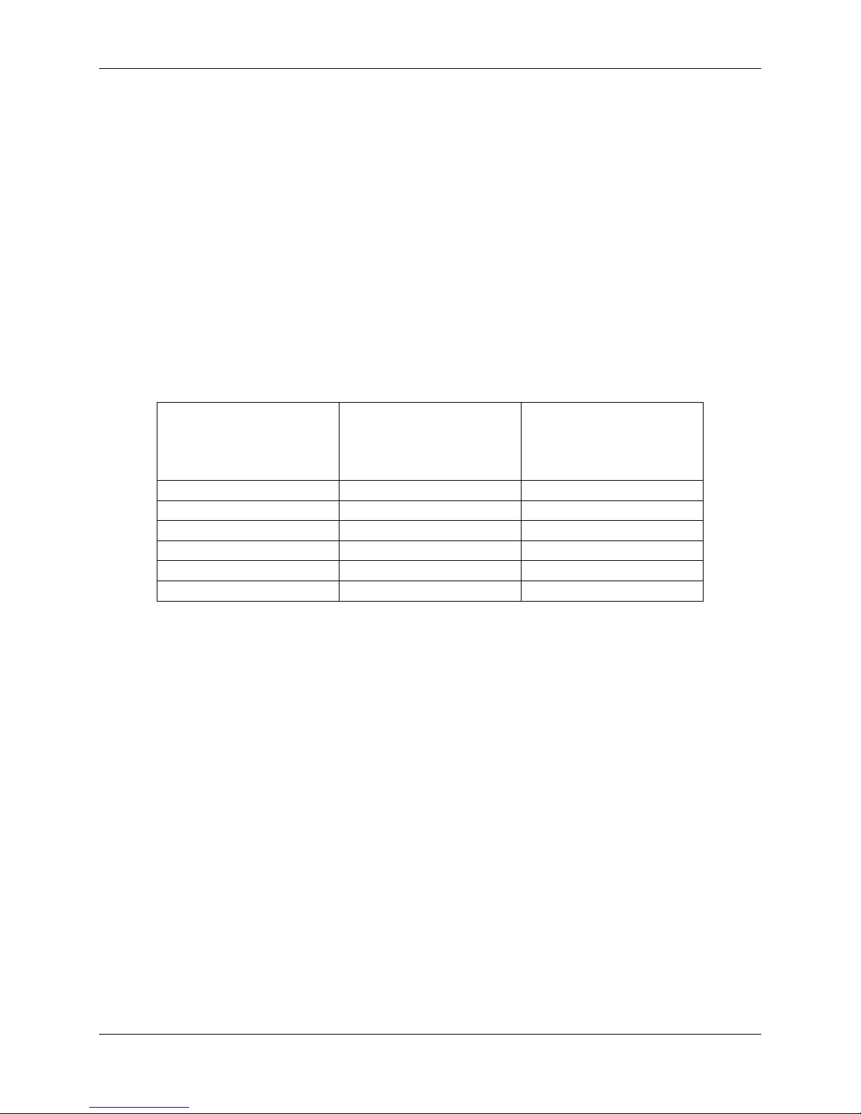
See the following chart for recommended fuse sizes:
3 Phase
Input Voltage
(VAC)
Input Current
at Maximum Output
(amps)
Recommended
Time-Delay Fuse
Size
(amps)
208V 60Hz
115
170
230V 60Hz
104
150
380V 50/60Hz
63
90
415V 50/60Hz
58
80
460V 60Hz
52
75
575V 60Hz
42
60
Use a Type SO power cable to connect the primary power to the Spirit
power supply. The power cable should have a 600 volt minimum rating
and should be sized according to local and national codes. Route the
power cable through the lower strain relief on the rear of the power supply
and connect it to the input terminal block TB5 as shown. TB5 is located
on the base of the power supply behind the left side cover. Be sure to
connect the primary ground cable to the ground stud on the input
terminal block.

Installation Spirit200a User’s Manual Rev J
This information is subject to the controls of the Export Administration Regulations [EAR]. This information shall not be provided to
non-U.S. persons or transferred by any means to any location outside the United States contrary to the requirements of the EAR.
3-4
TB5 Location

Installation Spirit200a User’s Manual Rev J
This information is subject to the controls of the Export Administration Regulations [EAR]. This information shall not be provided to
non-U.S. persons or transferred by any means to any location outside the United States contrary to the requirements of the EAR.
3-5
Power Supply Output Connections
Perform the following steps to connect the output of the power supply to
the RHF console and the work table. See figure below.
Power Supply Electrode Lead
1. Route one end of the #1/0AWG power supply electrode lead through
the upper strain relief on the rear of the power supply and connect it to
the electrode terminal.
2. Route the other end of the power supply electrode lead through the
strain relief on the RHF console and connect it to the cathode manifold.
Power Supply Nozzle Lead
1. Route one end of the #10AWG power supply nozzle lead through the
upper strain relief on the rear of the power supply and connect it to the
nozzle terminal.
2. Route the other end of the power supply nozzle Lead through the
strain relief on the RHF console and connect it to the pilot terminal on
the RHF console printed circuit board.
Power Supply CTP Sensor Lead
1. Route the end of the #14AWG power supply CTP sensor lead with the
ring terminal through the middle strain relief on the rear of the power
supply and connect it to the CTP terminal.
2. Route the end of the power supply CTP sensor lead with the fast-on
terminal through the strain relief on the RHF console and connect it to
the CTP sensor lead filter assembly.
RHF Console Control Cable
1. Connect the RHF console control cable plug labeled P16 to the
connector labeled P16 on the rear of the power supply.
2. Connect the RHF console control cable plug labeled P1 to the
connector labeled P1 on the RHF console.
Power Supply Coolant Supply Hose
1. Connect one end of the power supply coolant supply hose to the
coolant supply fitting on the rear of the power supply. Note that the
coolant supply fitting has right hand threads.
2. Connect the other end of the power supply coolant supply hose to the
coolant in fitting on the RHF console. Note that the coolant in fitting
has right hand threads.
1 2 3
4
5

Installation Spirit200a User’s Manual Rev J
This information is subject to the controls of the Export Administration Regulations [EAR]. This information shall not be provided to
non-U.S. persons or transferred by any means to any location outside the United States contrary to the requirements of the EAR.
3-6
Power Supply Coolant Return Hose
1. Connect one end of the power supply coolant return hose to the
coolant return fitting on the rear of the power supply. Note that the
coolant return fitting has left hand threads.
2. Connect the other end of the power supply coolant return hose to the
coolant out fitting on the RHF console. Note that the coolant out fitting
has left hand threads.
Work Ground Lead
1. Route one end of the #1/0AWG work ground lead through the middle
strain relief on the rear of the power supply and connect it to the work
terminal.
2. Connect the other end of the work ground lead to the star ground point
on the cutting table. The star ground point is generally referred to as
the common ground point on the cutting table where all subsystems of
the machine are grounded. This point is then connected to a driven
earth ground rod that should be as close as possible to the star
ground. The ground rod should have no other wires connected to it.
The ground rod should be at least 3/4 inches in diameter and should
be driven into the earth’s permanent moisture layer. The length of the
ground rod varies from installation to installation and should be
installed according to local and national codes. Refer to the National
Electrical Code, Article 250, Section H, Ground Electrode System for
additional information.
RHF Console Ground Connection
Perform the following steps to connect the chassis of the RHF console to
the cutting table. See figure below.
1. Connect one end of the RHF console ground lead to the ground stud
on the RHF console.
2. Connect the other end of the RHF console ground lead to chassis
ground on the cutting table. Make sure that good metal-to-metal contact is
made.
6
7
8

Installation Spirit200a User’s Manual Rev J
This information is subject to the controls of the Export Administration Regulations [EAR]. This information shall not be provided to
non-U.S. persons or transferred by any means to any location outside the United States contrary to the requirements of the EAR.
3-7

Installation Spirit200a User’s Manual Rev J
This information is subject to the controls of the Export Administration Regulations [EAR]. This information shall not be provided to
non-U.S. persons or transferred by any means to any location outside the United States contrary to the requirements of the EAR.
3-8
Torch Leads to RHF Console Connections
Perform the following steps to connect the torch leads to the RHF console.
See figure below.
Note: When making hose connections, only tighten the brass
fittings enough to make water or gas seals. The fittings are
subject to damage if over tightened.
Braided Shield
1. Remove the threaded ring from the brass shield connector on the end
of the braided shield. Route the torch leads through the opening in the
RHF console and push the shield connector through the hole until it is
seated against the side of the console.
2. Slide the threaded ring over the torch leads, thread it onto the brass
shield connector, and tighten firmly. The shield connector should
ground the braided shield to the case of the RHF console in order to
help reduce high frequency noise emission. Using an ohmmeter,
measure for zero ohms between the braided shield and the ground
stud located on the outside of the RHF console.
Torch Electrode/Coolant Supply Lead
• Connect the torch electrode/coolant supply lead to the brass cathode
manifold. Note that the torch electrode/coolant supply lead has right
hand threads.
Torch Coolant Return Lead
• Connect the torch coolant return lead to the brass cathode manifold.
Note that the torch coolant return lead has left hand threads.
Torch Nozzle Lead
• Connect the torch nozzle lead to the angled bracket on the red
standoff. Note that the torch nozzle lead has right hand threads.
Torch CTP Sensor Lead
• Connect the #18AWG torch CTP sensor lead to the red standoff as
shown.
9
10
11
12
13
 Loading...