

HMI connection manual

|
CATALOG |
|
1 SERIAL PORT OF HMI .................................................................................................................... |
1 |
|
1.1 |
Download port .......................................................................................................................... |
1 |
1.2 |
PLC port ................................................................................................................................... |
3 |
1.3 |
Expand port.............................................................................................................................. |
3 |
1.4 |
Ethernet port ............................................................................................................................ |
5 |
2 THE CONNECTION OF PLC AND HMI............................................................................................ |
8 |
|
2.1 |
XINJE FC series PLC .............................................................................................................. |
8 |
|
2.1.1Model .............................................................................................................................. |
8 |
|
2.1.2 Parameters .................................................................................................................... |
8 |
|
2.1.3 Cable making................................................................................................................. |
8 |
|
2.1.4 Device address .............................................................................................................. |
9 |
2.2 |
XINJE XC series PLC ............................................................................................................ |
10 |
|
2.2.1 Model ........................................................................................................................... |
10 |
|
2.2.2 Parameters .................................................................................................................. |
10 |
|
2.2.3 Cable making................................................................................................................ |
11 |
|
2.2.4 Device address ............................................................................................................ |
12 |
2.3 |
Mitsubishi FXseries PLC........................................................................................................ |
14 |
|
2.3.1Model ............................................................................................................................ |
14 |
|
2.3.2 Parameters .................................................................................................................. |
14 |
|
2.3.3 Cable making............................................................................................................... |
15 |
|
2.3.4 Device address ............................................................................................................ |
16 |
2.4 |
Mitsubishi FX3U/G series PLC .............................................................................................. |
17 |
|
2.4 .1 Model .......................................................................................................................... |
17 |
|
2.4 .2 Parameters ................................................................................................................. |
17 |
|
2.4 .3 Cable making.............................................................................................................. |
18 |
|
2.4 .4 Device address ........................................................................................................... |
18 |
2.5 |
Mitsubishi FX BD series PLC (RS232/485) ........................................................................... |
20 |
|
2.5.1 Device type .................................................................................................................. |
20 |
|
2.5.2 Parameters .................................................................................................................. |
20 |
|
2.5.3 Cable making............................................................................................................... |
21 |
|
2.5.3 Device address ............................................................................................................ |
22 |
2.6 |
Mitsubishi Q series PLC......................................................................................................... |
23 |
|
2.6 .1 Model .......................................................................................................................... |
23 |
|
2.6.2 Parameters .................................................................................................................. |
23 |
|
2.6.3 Cable making............................................................................................................... |
26 |
|
2.6.4 Device address ............................................................................................................ |
27 |
2.7 |
Siemens S7-200 series PLC ............................................................................................... |
29 |
|
2.7.1Model ............................................................................................................................ |
29 |
|
2.7.2 Parameters .................................................................................................................. |
29 |
|
2.7.3 Cable making............................................................................................................... |
30 |
|
2.7.4 Device address ............................................................................................................ |
30 |
|
ii |
|

2.8 Siemens S7-300/400 series PLC........................................................................................... |
32 |
2.8.1 Model ........................................................................................................................... |
32 |
2.8.2 Parameters .................................................................................................................. |
32 |
2.8.3 Cable making............................................................................................................... |
34 |
2.8.4 Device address ............................................................................................................ |
35 |
2.9 OMRON SYSMAC series PLC............................................................................................ |
36 |
2.9.1 Device model ............................................................................................................... |
36 |
2.9.2 Parameters .................................................................................................................. |
37 |
2.9.3 Cable making............................................................................................................... |
38 |
2.9.4 Device address ............................................................................................................ |
39 |
2.10 Koyo S series PLC............................................................................................................... |
41 |
2.10.1 Device model ............................................................................................................. |
41 |
2.10.2 Parameters ................................................................................................................ |
42 |
2.10.3 Cable making............................................................................................................. |
43 |
2.10.4 Device address .......................................................................................................... |
44 |
2.11 Koyo DL series PLC ............................................................................................................. |
45 |
2.11.1 Device type ................................................................................................................ |
45 |
2.11.2 Parameters................................................................................................................. |
45 |
2.11.3 Cable making ............................................................................................................. |
45 |
2.11.4 Device address .......................................................................................................... |
46 |
2.12 Delta DVP series PLC.......................................................................................................... |
47 |
2.12.1Model .......................................................................................................................... |
47 |
2.12.2 Parameters ................................................................................................................ |
47 |
2.12.3 Cable making............................................................................................................. |
47 |
2.12.4 Device address .......................................................................................................... |
48 |
2.13 LG Master-K(CPU Direct) series PLC ................................................................................. |
49 |
2.13.1 Device model ............................................................................................................. |
49 |
2.13.2 Parameters ................................................................................................................ |
49 |
2.13.3 Cable making............................................................................................................. |
50 |
2.13.4 Device address .......................................................................................................... |
50 |
2.14 LG Master-K(Cnet) series PLC............................................................................................ |
52 |
2.14.1 Device model ............................................................................................................. |
52 |
2.14.2 Parameters ................................................................................................................ |
52 |
2.14.3 Cable making............................................................................................................. |
53 |
2.14.4 Device address .......................................................................................................... |
54 |
2.15 LG Glofa(Cnet) series PLC.................................................................................................. |
55 |
2.15.1 Device model ............................................................................................................. |
55 |
2.15.2 Parameters ................................................................................................................ |
55 |
2.15.3 Cable making............................................................................................................. |
57 |
2.15.4 Device address .......................................................................................................... |
58 |
2.16 LG XGT(CPU Direct) series PLC......................................................................................... |
60 |
2.16.1 Device model ............................................................................................................. |
60 |
2.16.2 Parameters ................................................................................................................ |
60 |
2.16.3 Cable making............................................................................................................. |
60 |
|
iii |

2.16.4 Device address .......................................................................................................... |
61 |
2.17 Matsushita MEWNET FP series PLC .................................................................................. |
62 |
2.17.1Device model .............................................................................................................. |
62 |
2.17.2 Parameters ................................................................................................................ |
63 |
2.17.3 Cable making............................................................................................................. |
64 |
2.17.4 Device address .......................................................................................................... |
65 |
2.18 Schneider PLC .................................................................................................................. |
67 |
2.18.1Device model .............................................................................................................. |
67 |
2.18.2 Parameters ................................................................................................................ |
67 |
2.18.3 Cable making............................................................................................................. |
69 |
2.18.4 Device address .......................................................................................................... |
69 |
2.19 Fatek FB series PLC............................................................................................................ |
70 |
2.19.1 Device model ............................................................................................................. |
70 |
2.19.2 Parameters ................................................................................................................ |
70 |
2.19.3 Cable making............................................................................................................. |
71 |
2.19.4 Device address .......................................................................................................... |
72 |
2.20 Vigor VIGOR PLC ................................................................................................................ |
73 |
2.20.1 Device model ............................................................................................................. |
73 |
2.20.2 Parameters ................................................................................................................ |
73 |
2.20.3 Cable making............................................................................................................. |
73 |
2.20.4 Device address .......................................................................................................... |
75 |
2.21 Fuji SPB series PLC ............................................................................................................ |
76 |
2.21.1 Device model ............................................................................................................. |
76 |
2.21.2 Parameters ................................................................................................................ |
76 |
2.21.3 Cable making............................................................................................................. |
76 |
2.21.4 Device address .......................................................................................................... |
77 |
2.22 Keyence KV series PLC....................................................................................................... |
79 |
2.22.1Device model .............................................................................................................. |
79 |
2.22.2 Parameters ................................................................................................................ |
79 |
2.22.3 Cable making............................................................................................................. |
79 |
2.22.4 Device address .......................................................................................................... |
81 |
2.23 Emerson EC20 series PLC.................................................................................................. |
82 |
2.23.1Device model .............................................................................................................. |
82 |
2.23.2 Parameters ................................................................................................................ |
82 |
2.23.3 Cable making............................................................................................................. |
82 |
2.23.4 Device address .......................................................................................................... |
83 |
2.24 OEMax NX7 series PLC ...................................................................................................... |
84 |
2.24.1 Device model ............................................................................................................. |
84 |
2.24.2 Device address .......................................................................................................... |
84 |
2.24.3 Cable making............................................................................................................. |
84 |
2.24.4 Device address .......................................................................................................... |
86 |
2.25 Bosch Rexroth IndraControl L40 series PLC....................................................................... |
87 |
2.25.1 Device model ............................................................................................................. |
87 |
2.25.2 Parameters ................................................................................................................ |
87 |
iv |
|

2.25.3 Cable making............................................................................................................. |
87 |
2.25.4 Device address .......................................................................................................... |
88 |
2.26 OPTO 22 SNAP series PLC ................................................................................................ |
89 |
2.26.1 Device model ............................................................................................................. |
89 |
2.26.2 Parameters ................................................................................................................ |
89 |
2.26.3 Cable making............................................................................................................. |
89 |
2.26.4 Device address .......................................................................................................... |
90 |
2.27 SAIA-Burgess PCD series PLC ........................................................................................... |
91 |
2.27.1 Device model ............................................................................................................. |
91 |
2.27.2 Parameters ................................................................................................................ |
92 |
2.27.3 Cable making............................................................................................................. |
92 |
2.27.4 Device address .......................................................................................................... |
96 |
2.28 Allen-Bradley series PLC ..................................................................................................... |
96 |
2.28.1 Device model ............................................................................................................. |
96 |
2.28.2 Parameters ................................................................................................................ |
96 |
2.28.3 Cable making............................................................................................................. |
99 |
2.28.4 Device address .......................................................................................................... |
99 |
2.29 Xinje V5 series inverter ...................................................................................................... |
101 |
2.29.1 Device model ........................................................................................................... |
101 |
2.29.2 Parameters .............................................................................................................. |
101 |
2.29.3 Cable making........................................................................................................... |
102 |
2.30 SHIMADEN ........................................................................................................................ |
103 |
2.30.1 Device model ........................................................................................................... |
103 |
2.30.2 Parameters .............................................................................................................. |
103 |
2.30.3 Cable making........................................................................................................... |
103 |
2.30.4 Device address ........................................................................................................ |
104 |
2.31 Modbus RTU (panel is Master).......................................................................................... |
105 |
2.31.1 Device model ........................................................................................................... |
105 |
2.31.2 Parameters .............................................................................................................. |
105 |
2.31.3 Cable making........................................................................................................... |
105 |
2.31.4 Device address ........................................................................................................ |
106 |
2.32 Modbus ASCII (Panel is Master)........................................................................................ |
107 |
2.32.1Device model ............................................................................................................ |
107 |
2.32.2 Parameters .............................................................................................................. |
107 |
2.32.3 Cable making........................................................................................................... |
107 |
2.32.4 Device address ........................................................................................................ |
108 |
2.33 Modbus slave (panel is Slave)........................................................................................... |
109 |
2.33.1Device model ............................................................................................................ |
109 |
2.33.2 Parameters .............................................................................................................. |
109 |
2.33.3 Cable making........................................................................................................... |
109 |
2.33.4 Device address ......................................................................................................... |
110 |
2.34 ABB PLC ............................................................................................................................. |
111 |
2.34.1Device model ............................................................................................................. |
111 |
2.34.2 Parameters ............................................................................................................... |
111 |
|
v |

|
2.34.3 Cable making............................................................................................................ |
112 |
|
2.34.4 Device address ......................................................................................................... |
113 |
2.35 IDEC.................................................................................................................................... |
114 |
|
|
2.35.1 Device type ............................................................................................................... |
114 |
|
2.35.2 Parameters ............................................................................................................... |
114 |
|
2.35.3 Cable making............................................................................................................ |
114 |
|
2.35.4 Device address ......................................................................................................... |
115 |
2.36 TAIAN .................................................................................................................................. |
116 |
|
|
2.36.1 Device type ............................................................................................................... |
116 |
|
2.36.2 Parameters ............................................................................................................... |
117 |
|
2.36.3 Cable making............................................................................................................ |
117 |
|
2.36.4 Device address ......................................................................................................... |
118 |
2.37 YuDian AI ............................................................................................................................ |
119 |
|
|
2.37.1 Device address ......................................................................................................... |
119 |
|
2.37.2 Parameters ............................................................................................................... |
119 |
|
2.37.3 Cable making............................................................................................................ |
119 |
|
2.37.4 Device address ........................................................................................................ |
120 |
2.38 Inovance PLC..................................................................................................................... |
121 |
|
|
2.38.1 Device type .............................................................................................................. |
121 |
|
2.38.2 Parameter ................................................................................................................ |
121 |
|
2.38.3 Cable making........................................................................................................... |
122 |
|
2.38.4 Device address ........................................................................................................ |
122 |
2.39 |
HaiWell PLC .................................................................................................................... |
124 |
|
2.39.1 Device type .............................................................................................................. |
124 |
|
2.39.2 Parameters .............................................................................................................. |
124 |
|
2.39.3 Cable making........................................................................................................... |
124 |
|
2.39.4 Device address ........................................................................................................ |
125 |
2.40 |
Hollias PLC...................................................................................................................... |
126 |
|
2.40.1 Device type .............................................................................................................. |
126 |
|
2.40.2 Parameters .............................................................................................................. |
126 |
|
2.40.3 Cable making........................................................................................................... |
126 |
|
2.40.4 Device address ........................................................................................................ |
127 |
2.41 |
Delta (temperature controller) ......................................................................................... |
128 |
|
2.41.1 Device type .............................................................................................................. |
128 |
|
2.41.2 Parameters .............................................................................................................. |
128 |
|
2.41.3 Cable making........................................................................................................... |
128 |
|
2.41.4 Device address ........................................................................................................ |
129 |
2.42 |
Siemens S7-1200............................................................................................................ |
130 |
|
2.42.1 Device type .............................................................................................................. |
130 |
|
2.42.2 Parameters .............................................................................................................. |
130 |
|
2.42.3 Cable making........................................................................................................... |
135 |
|
2.42.4 Device address ........................................................................................................ |
136 |
2.43 Mitsubishi FR series inverter ............................................................................................. |
137 |
|
|
2.43.1 Device type .............................................................................................................. |
137 |
|
|
vi |

2.43.2 Parameters .............................................................................................................. |
137 |
2.43.3 Cable making........................................................................................................... |
140 |
2.44 Sanken VM06 inverter ....................................................................................................... |
141 |
2.44.1 Device type .............................................................................................................. |
141 |
2.44.2 Parameters .............................................................................................................. |
141 |
2.44.3 Cable making........................................................................................................... |
143 |
2.44.4 Device address ........................................................................................................ |
143 |
2.45 XINJE XD/XE series .......................................................................................................... |
145 |
2.45.1 Device type .............................................................................................................. |
145 |
2.45.2 Parameters .............................................................................................................. |
145 |
2.45.3 Cable making........................................................................................................... |
146 |
2.45.4 Device address ........................................................................................................ |
147 |
2.46 LG XGB series PLC ........................................................................................................... |
149 |
2.46.1 Device type .............................................................................................................. |
149 |
2.46.2 Parameters .............................................................................................................. |
149 |
2.46.3 Cable making........................................................................................................... |
153 |
2.46.4 Device address ........................................................................................................ |
154 |
2.47 Koyo Click series ............................................................................................................... |
155 |
2.47.1 Device type .............................................................................................................. |
155 |
2.47.2 Parameter setting .................................................................................................... |
155 |
2.47.3 Cable making........................................................................................................... |
156 |
2.47.4 Device address ........................................................................................................ |
156 |
2.48 Mitsubishi Melsec protocol................................................................................................. |
157 |
2.48.1 Device type .............................................................................................................. |
157 |
2.48.2 Parameter settings................................................................................................... |
158 |
2.48.3 Cable making........................................................................................................... |
161 |
2.48.4 Device address ........................................................................................................ |
162 |
2.49 Free type (panel is slave)................................................................................................... |
162 |
2.49.1 Device type .............................................................................................................. |
162 |
2.49.2 Parameter setting .................................................................................................... |
163 |
2.49.3 Cable making........................................................................................................... |
165 |
2.49.4 Device address ........................................................................................................ |
166 |
2.50 Modbus-TCP device .......................................................................................................... |
166 |
2.50.1 Device type .............................................................................................................. |
166 |
2.50.2 Parameter setting .................................................................................................... |
166 |
2.50.3 Cable making........................................................................................................... |
172 |
2.50.4 Device address ........................................................................................................ |
173 |
2.51 Mitsubishi FX5U series ...................................................................................................... |
173 |
2.51.1 Device type .............................................................................................................. |
173 |
2.51.2 Parameter setting .................................................................................................... |
173 |
2.51.3 Cable making........................................................................................................... |
177 |
2.51.4 Device address ........................................................................................................ |
178 |
2.52 Siemens S7-200 smart series............................................................................................ |
179 |
2.52.1 Device type .............................................................................................................. |
179 |
|
vii |

2.52.2 Parameter setting .................................................................................................... |
179 |
2.52.3 Cable making........................................................................................................... |
182 |
2.52.4 Device address ........................................................................................................ |
184 |
2.53 Siemens S7-300 series...................................................................................................... |
185 |
2.53.1 Device type .............................................................................................................. |
185 |
2.53.2 Parameter setting .................................................................................................... |
185 |
2.53.3 Cable making........................................................................................................... |
188 |
2.53.4 Device address ........................................................................................................ |
190 |
2.54 X-NET communication ....................................................................................................... |
191 |
2.54.1 Device type .............................................................................................................. |
191 |
2.54.2 HMI setting............................................................................................................... |
191 |
2.54.3 XD series PLC setting (PLC hardware V3.2.2 and up) ........................................... |
197 |
2.54.4 Cable making........................................................................................................... |
200 |
2.54.5 Device address ........................................................................................................ |
202 |
2.55 Keyence KV5000 ............................................................................................................... |
204 |
2.55.1 Device type .............................................................................................................. |
204 |
2.55.2 Parameter setting .................................................................................................... |
204 |
2.55.3 Cable making........................................................................................................... |
207 |
2.55.4 Device address ........................................................................................................ |
208 |
2.56 LG XGT .............................................................................................................................. |
209 |
2.56.1 Device type .............................................................................................................. |
209 |
2.56.2 Parameter setting .................................................................................................... |
209 |
2.56.3 Cable making............................................................................................................ |
211 |
2.56.4 Device address ........................................................................................................ |
212 |
2.57 Haiwell................................................................................................................................ |
213 |
2.57.1 Device type .............................................................................................................. |
213 |
2.57.2 Parameters .............................................................................................................. |
213 |
2.57.3 Cable making........................................................................................................... |
215 |
2.57.4 Device address ........................................................................................................ |
216 |
viii
1 Serial port of HMI
This chapter will introduce the serial port of HMI.
1.1 Download port
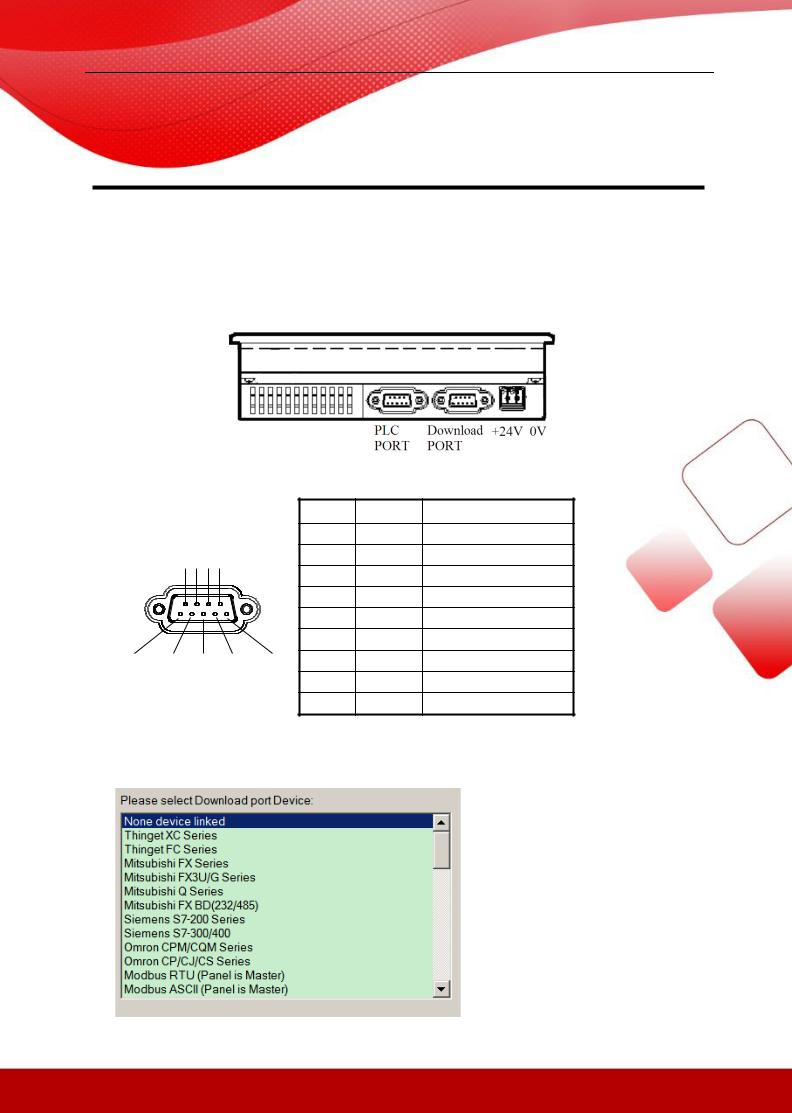
The HMI of XINJE TP and TH series are configured PLC port and download port. Next, it will introduce the port and function. The following diagram is the port of TP460-L.
Download port: |
|
|
|
|
|
||
|
|
|
|
|
Pin |
Name |
Explanation |
|
9 8 7 6 |
|
1 |
NC |
Vacant |
||
|
|
2 |
RXD |
RS232 receive |
|||
|
|
|
|
|
|||
|
|
|
|
|
3 |
TXD |
RS232 send |
|
|
|
|
|
4 |
A |
RS485 + |
|
|
|
|
|
5 |
GND |
Ground |
|
|
|
|
|
6 |
NC |
Vacant |
5 |
4 |
3 |
2 |
1 |
7 |
B |
RS485 - |
|
|
|
|
|
8 |
NC |
Vacant |
|
|
|
|
|
9 |
NC |
Vacant |
1. Choose the device to communicate with download port
(a) Build a new project in Touchwin software, choose download port device
1
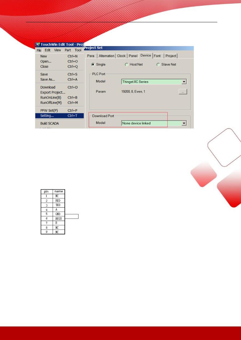
(b) For current project, please set it in the Touchwin software:
2. Mode switching for download port
The default mode of TH series download port is communication. But it is download mode for TP series. If the download port of TP series needs to switch to communication mode, two pins of the download port must be shorted. Please see the following diagram.
(1)Cut off the power of TP series HMI, connect pin5 and pin6 of TP download port.
(2)Power on the HMI, take away the connection cable, the download port will be in communication mode.
Note: 1. if the HMI needs to download program, please restart the HMI. 2. Please connect the pin 5 and 6 directly.
2
1.2 PLC port
PLC port: |
|
|
|
|
|
|
|
|
|
|
|
|
Pin |
Name |
Explanation |
|
9 8 7 6 |
|
1 |
TD+ |
RS422 send - |
||
|
|
2 |
RXD |
RS232 receive |
|||
|
|
|
|
|
|||
|
|
|
|
|
3 |
TXD |
RS232 send |
|
|
|
|
|
4 |
A |
RS485 + |
|
|
|
|
|
5 |
GND |
Ground |
|
|
|
|
|
6 |
TD- |
RS422 send - |
5 |
4 |
3 |
2 |
1 |
7 |
B |
RS485 - |
|
|
|
|||||
|
|
|
|
|
8 |
RDD- |
RS422 receive - |
|
|
|
|
|
9 |
RDD+ |
RS422 receive + |
For real application, pelase refer to chapter 2 for cable making. Refer to chapter 1.1 for
download port settings.
1.3 Expand port
Expand port:
|
|
|
|
|
Pin |
Definition |
Explanation |
|
9 8 7 6 |
|
1 |
A |
RS485 + |
||
|
|
2 |
|
|
|||
|
|
|
|
|
|
|
|
|
|
|
|
|
3 |
|
|
|
|
|
|
|
4 |
|
|
|
|
|
|
|
5 |
|
|
|
|
|
|
|
6 |
B |
RS485 - |
5 |
4 |
3 |
2 |
1 |
7 |
|
|
|
|
|
|
|
8 |
|
|
|
|
|
|
|
9 |
|
|
Note: only TH765-NT3/NU3 has this expand port.
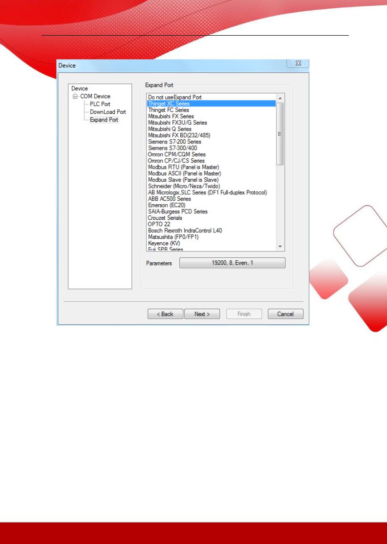
1. choose expand port device
(1) Build a new project, click expand port, and choose the device
3
(2) For existed project, click File/setting/device/expand port to set the PLC model.
4
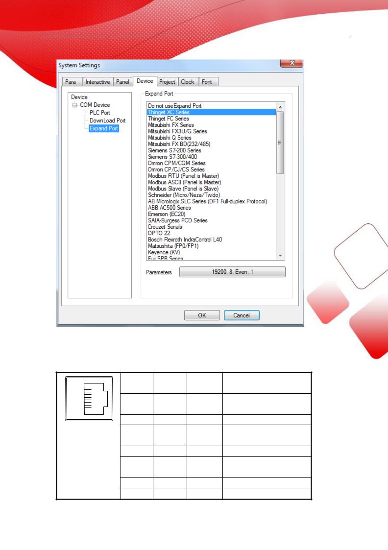
1.4 Ethernet port
RJ45 Ethernet port:
Pin |
Color |
Definitio |
Explanation |
|
8 |
|
n |
|
|
1 |
Orange |
TXD+ |
Data send + |
|
1 |
white |
|||
|
|
|||
|
|
|
||
2 |
Orange |
TXD- |
Data send - |
|
3 |
Green |
RXD+ |
Data receive + |
|
|
white |
|||
|
|
|
||
4 |
Blue |
- |
- |
|
5 |
Blue |
- |
- |
|
|
white |
|||
|
|
|
||
6 |
Green |
RXD- |
Data receive - |
|
7 |
Brown |
- |
- |
|
|
|
5 |
|
|
white |
|
|
8 |
Brown |
- |
- |
Note: only TG765-ET/TG865-ET/TGA62-ET/TGC65-ET has Ethernet port.
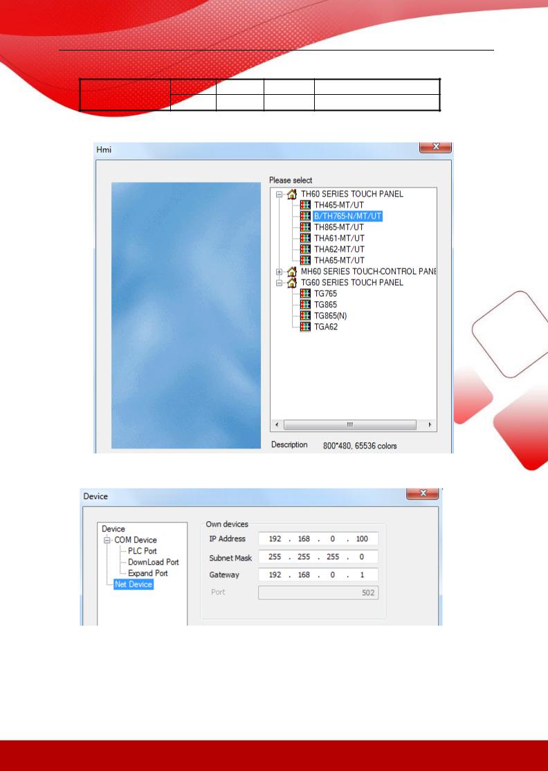
1.Build a new project, choose TG model in the list.
2. Click next, choose net device. Set the IP address of TG series HMI.
6
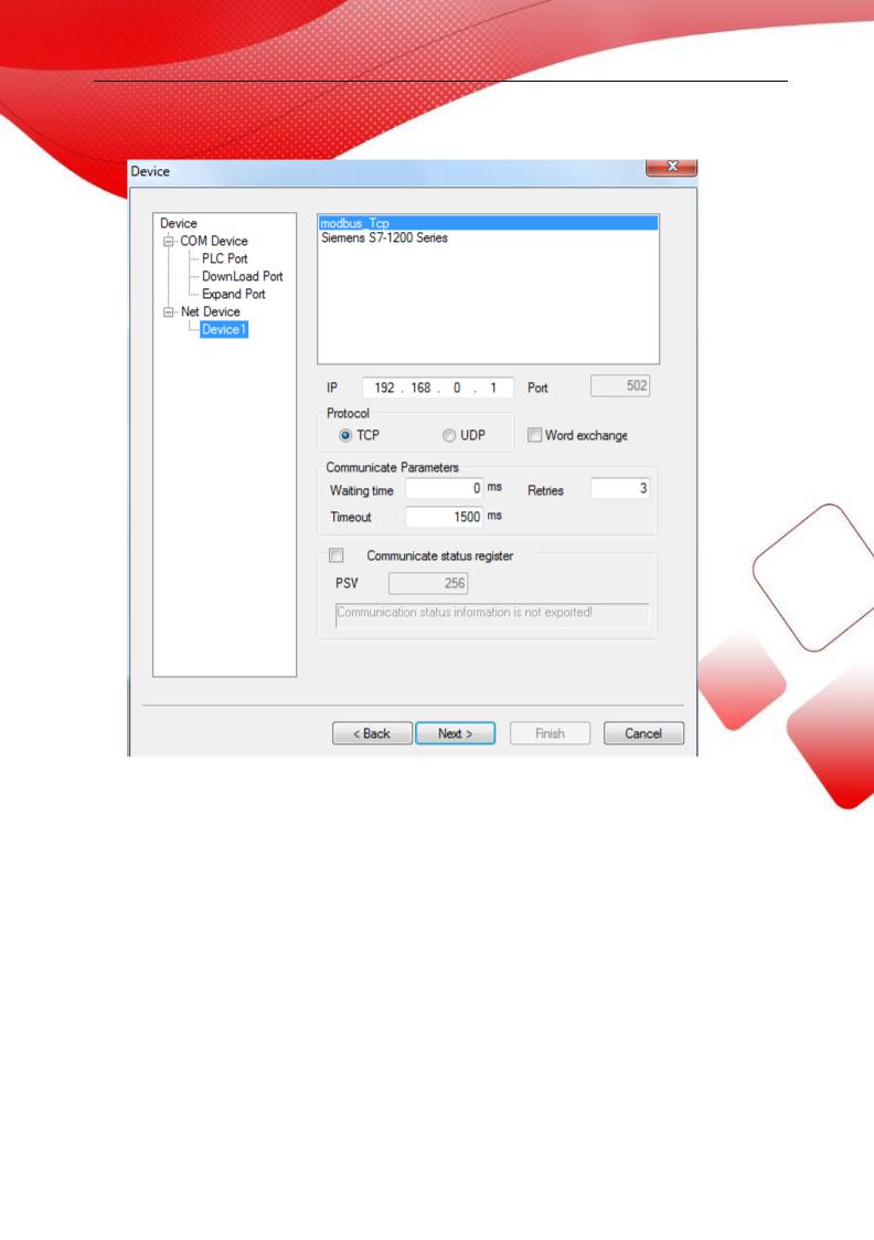
3. Right click net device, build a new Ethernet device.
Note: this function support local area network, but not support wide area network
7
2 The connection of PLC and HMI
This chapter will introduce the connection between PLC and HMI.
Please don’t pull out or plug the cable when power on, the serial port may be damaged.
2.1 XINJE FC series PLC
2.1.1Model
|
Serie |
|
|
CPU |
|
|
Connecte |
|
|
Port |
|
|
Cable |
|
|
Device |
|
|
s |
|
|
|
|
d module |
|
|
|
|
making |
|
|
|
|||
|
|
|
|
|
|
|
|
|
|
|
|
|
|
|
|||
|
|
|
|
|
|
|
CPU |
|
RS232 |
|
Fig1 |
|
|
|
|||
|
|
|
|
XC32V2-CPU030427 |
|
|
direct |
|
|
|
|
|
|
Xinje FC |
|||
|
FC |
|
|
|
|
RS485 |
|
|
|
|
|||||||
|
|
-R5 |
|
|
connectio |
|
|
|
|
Fig2 |
|
series |
|||||
|
|
|
|
|
|
|
|
|
|
|
|||||||
|
|
|
|
|
|
|
n |
|
|
|
|
|
|
|
|
|
|
|
|
|
|
|
|
|
|
|
|
|
|
|
|
|
|
|
|
2.1.2 Parameters
HMI parameters:
Parameters |
Settings |
Choices for settings |
Item |
PLC type |
FC series |
|
|
|
|
|
|
Port |
RS232 |
RS232or RS485 |
|
|
|
|
|
Data bit |
8 |
7 or 8 |
|
|
|
|
|
Stop bit |
1 |
1 or 2 |
|
|
|
|
|
Parity |
Odd parity |
Odd/even/no parity |
|
|
|
|
|
Baud rate |
9600 |
4800/38400/9600/115200/19200/187500 |
|
|
|
|
|
Station No. |
0 |
0~255 |
|
|
|
|
|
The default communication parameters of FC: 9600, 8, 1, odd parity, station No.0.
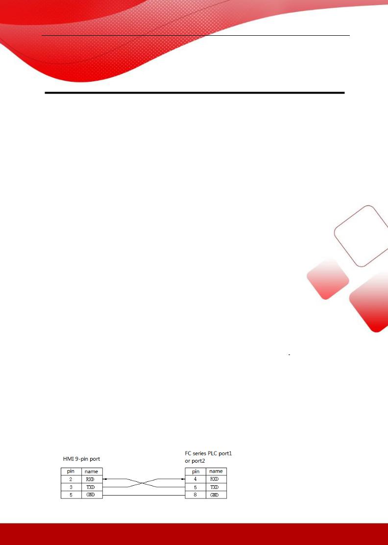
2.1.3 Cable making
(a) Connect to FC series CPU (RS232 port)
8

Fig1
(b) Connect to FC series PLC CPU (RS485 port)
Fig2
2.1.4 Device address
PLC address |
Range |
Data type |
Explanation |
X |
0~337 |
Bit |
External input coil |
|
|
|
|
Y |
0~337 |
Bit |
External output coil |
|
|
|
|
M |
0~383 |
Bit |
Internal coil |
|
|
|
|
SM |
0~96 |
Bit |
Special coil |
|
|
|
|
T |
0~128 |
Bit |
Timer |
|
|
|
|
C |
0~128 |
Bit |
Counter |
|
|
|
|
W |
0~2047 |
Word/DWord |
Data register |
|
|
|
|
FW |
0~191 |
Word/DWord |
FlashROM register |
|
|
|
|
TW |
0~127 |
Word/ |
Timer register |
|
|
|
|
CW |
0~127 |
Word/ |
Counter register |
|
|
|
|
SW |
0~111 |
Word//DWord |
Special register |
|
|
|
|
WX |
0~13 |
Word//DWord |
Input coil register |
|
|
|
|
WY |
0~13 |
Word//DWord |
Output coil register |
|
|
|
|
WM |
0~23 |
Word//DWord |
Interla coil register |
|
|
|
|
9

2.2 XINJE XC series PLC
2.2.1 Model
|
Series |
|
CPU |
|
Connected module |
|
Port |
|
Cable making |
|
Device |
|
|
|
|
|
|
CPU |
direct |
|
RS232 |
|
Fig1 |
|
|
|
|
|
|
|
connection |
|
|
|
|
|
|
|
|
|
|
XC1\XC2\ |
|
|
|
RS485 |
|
Fig 2 |
|
Xinje XC |
|
|
XC |
|
|
|
|
|
|
|
|
|
||
|
|
|
XC-RS485-BD |
|
RS232 |
|
Fig 3 |
|
||||
|
|
XC3\XC5 |
|
|
|
|
series |
|||||
|
|
|
|
(communication |
|
|
|
|
|
|||
|
|
|
|
|
RS485 |
|
Fig 4 |
|
||||
|
|
|
|
|
|
|
|
|
||||
|
|
|
|
|
extension board) |
|
|
|
|
|
||
|
|
|
|
|
|
|
|
|
|
|
||
|
|
|
|
|
|
|
|
|
|
|
|
|
2.2.2 Parameters
HMI parameters:
Parameter |
Recommend settings |
Choices of settings |
Item |
PLC type |
XC series |
FC/XC series |
|
|
|
|
|
Port |
RS232 |
RS232 or RS485 |
|
|
|
|
|
Data bit |
8 |
7 or 8 |
|
|
|
|
|
Stop bit |
1 |
1 or 2 |
|
|
|
|
|
Parity |
Even parity |
Even/odd/no parity |
|
|
|
|
|
Baud rate |
19200 |
4800/38400/9600/115200/19200/187500 |
|
|
|
|
|
Station No. |
1 |
0~255 |
|
|
|
|
|
The default communication parameters of XC: 19200, 8, 1, even, station No.1.
PLC settings:
Open XCPpro software:
10
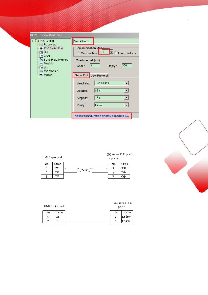
2.2.3 Cable making
(a) Connect to XC series PLC CPU (RS232 port)
Fig1
(b) Connect to XC series PLC CPU (RS485 port)
Fig2
(c) Connect via XC-RS485-BD (RS232)
11
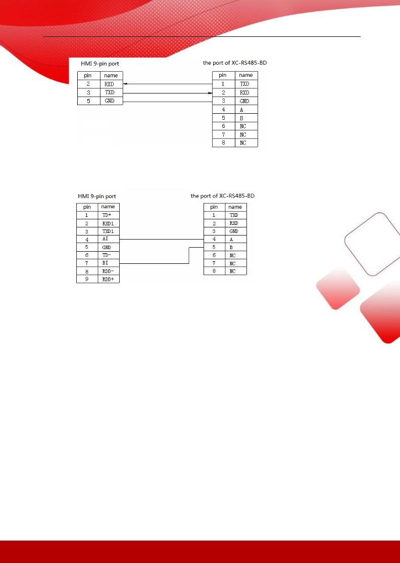
Fig3
(d) Connect via XC-RS485-BD (RS485)
Fig4
2.2.4 Device address
PLC address |
Range |
Data type |
Explanation |
X |
0~543 |
Bit |
External input coil |
|
|
|
|
Y |
0~543 |
Bit |
External input coil |
|
|
|
|
M |
0~7999 |
Bit |
Internal coil |
|
|
|
|
S |
0~1023 |
Bit |
Internal coil |
|
|
|
|
M8XXX |
0~511 |
Bit |
Internal special register |
|
|
|
|
T |
0~639 |
Bit |
Timer |
|
|
|
|
C |
0~639 |
Bit |
Counter |
|
|
|
|
D |
0~7999 |
Word//DWord |
Data register |
|
|
|
|
TD |
0~639 |
Word//DWord |
Timer register |
|
|
|
|
CD |
0~639 |
Word//DWord |
Counter register |
|
|
|
|
D8XXX |
0~511 |
Word//DWord |
Special register |
|
|
|
|
FD |
0~1535 |
Word//DWord |
FlashROM register |
|
|
|
|
FD8XXX |
0~511 |
Word//DWord |
Output register |
|
|
|
|
ED |
0~36862 |
Word//DWord |
Extend register |
|
|
|
|
DM |
7984 |
Word |
Data register |
|
|
|
|
|
|
12 |
|
DX |
0~52 |
Word |
Data register |
|
|
|
|
DY |
0~52 |
Word |
Data register |
|
|
|
|
DS |
0~1008 |
Word |
Data register |
|
|
|
|
DM8XXX |
0~496 |
Word |
Data register |
|
|
|
|
DT |
0~603 |
Word |
Data register |
|
|
|
|
DC |
0~619 |
Word |
Data register |
|
|
|
|
ID |
0~9999 |
Word//DWord |
Analog input |
|
|
|
|
QD |
0~9999 |
Word//DWord |
Analog output |
|
|
|
|
13

2.3 Mitsubishi FXseries PLC
2.3.1Model
|
Series |
|
|
CPU |
|
|
Connected |
|
|
Port |
|
|
Cable |
|
|
Device |
|
|
|
|
|
|
module |
|
|
|
|
making |
|
|
|
||||
|
|
|
|
|
|
|
|
|
|
|
|
|
|
|
|
||
|
|
|
|
FX0N |
|
CPU direct |
|
RS422 |
|
Fig1 |
|
Mitsubishi FX |
|||||
|
|
|
|
FX1N |
|
connection |
|
|
|
series PLC |
|||||||
|
|
|
|
|
|
|
|
|
|
|
|
||||||
|
|
|
|
FX2N |
|
RS232-BD |
|
RS232 |
|
Fig 2 |
|
Mitsubishi |
|||||
|
|
|
|
FX1S |
|
|
|
|
|
|
|
|
|
|
|||
|
|
|
|
|
RS485\422-B |
|
RS485 |
|
Fig 3 |
|
|||||||
|
|
|
|
|
|
|
|
FXBD(232\485) |
|||||||||
|
|
|
|
FX3U |
|
D |
|
|
|
|
|
|
|
||||
|
FX |
|
|
|
RS422 |
|
|
|
|
||||||||
|
|
|
|
|
|
|
|
|
|
||||||||
|
|
|
|
|
|
|
|
|
|
|
|
|
|
|
|
||
|
|
FX3G |
|
CPU direct |
|
|
|
|
|
|
|
Mitsubishi FX |
|||||
|
|
|
|
|
|
|
|
|
|
|
|
||||||
|
|
|
|
FX0 |
|
|
RS422 |
|
Fig 1 |
|
|||||||
|
|
|
|
|
connection |
|
|
|
series PLC |
||||||||
|
|
|
|
FX1 |
|
|
|
|
|
|
|
|
|||||
|
|
|
|
|
|
|
|
|
|
|
|
|
|
|
|
||
|
|
|
|
|
|
|
|
|
|
|
|
|
|
|
|
||
|
|
|
|
FX2 |
|
CPU direct |
|
RS422 |
|
Fig 4 |
|
Mitsubishi FX |
|||||
|
|
|
|
|
connection |
|
|
|
series PLC |
||||||||
|
|
|
|
|
|
|
|
|
|
|
|
|
|
||||
|
|
|
|
|
|
|
|
|
|
|
|
|
|
|
|
|
|
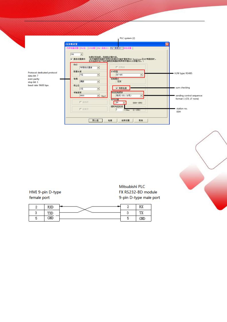
2.3.2 Parameters
HMI settings:
Parameter |
Recommend |
Choices of settings |
Item |
|
settings |
|
|
PLC type |
FX series |
|
|
|
|
|
|
Dat bit |
7 |
7 or 8 |
|
|
|
|
|
Stop bit |
1 |
1 or 2 |
|
|
|
|
|
Parity |
Even parity |
Even/odd/no parity |
|
|
|
|
|
Baud rate |
9600 |
4800/9600/19200/38400/56000/57600/11 |
|
|
|
5200/187500 |
|
|
|
|
|
Station No. |
0 |
0~255 |
|
|
|
|
|
The default parameters of Mitsubishi FX series PLC: 9600, 7, 1, even, station No.0.
PLC settings:
14
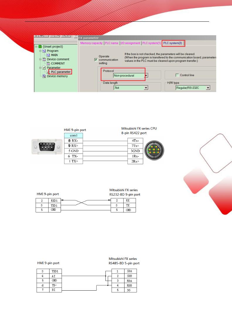
2.3.3 Cable making
(a) FX1N\2N\3U\3G\1S series PLC, RS422 port:
Fig1
(b) FX series PLC uses RS232-BD:
Fig2
(c) FX series PLC uses RS485BD:
Fig3
15
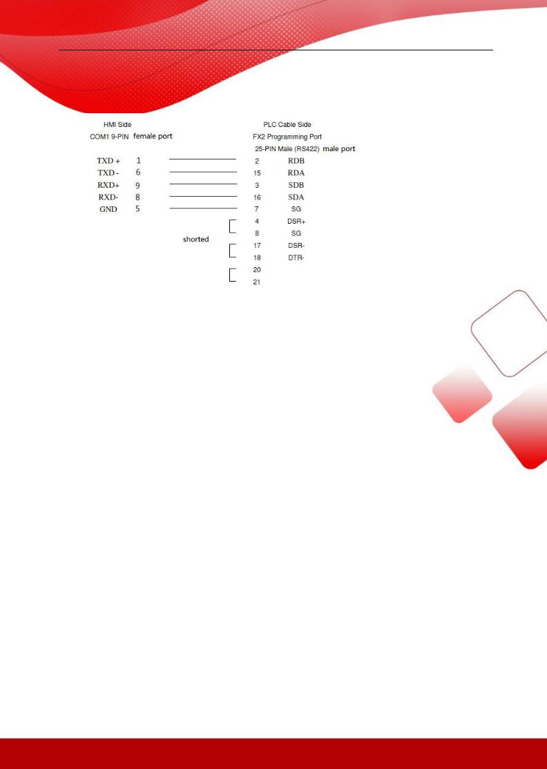
(d) FX2 series PLC:
Fig4
2.3.4 Device address
PLC address |
Range |
Data type |
Explanation |
X |
0~177 |
Bit |
External input coil |
|
|
|
|
Y |
0~177 |
Bit |
External output coil |
|
|
|
|
M |
0~8255 |
Bit |
Internal coil |
|
|
|
|
S |
0~999 |
Bit |
Stepper coil |
|
|
|
|
T |
0~255 |
Bit |
Timer |
|
|
|
|
C |
0~255 |
Bit |
Counter |
|
|
|
|
C16 |
0~199 |
Word/DWord |
16-bit counter |
|
|
|
|
C32 |
200~255 |
DWord |
32-bit counter |
|
|
|
|
D |
0~8255 |
Word/DWord |
Data register |
|
|
|
|
T |
0~255 |
Word/DWord |
Current value |
|
|
|
|
X |
0~177 |
Word/DWord |
Data register |
|
|
|
|
Y |
0~177 |
Word/DWord |
Data register |
|
|
|
|
M |
0~8255 |
Word/DWord |
Data register |
|
|
|
|
S |
0~999 |
Word/DWord |
Data register |
|
|
|
|
16

2.4 Mitsubishi FX3U/G series PLC
2.4 .1 Model
|
|
|
|
|
|
|
Connected |
|
|
|
|
|
|
|
|
Choose PLC type |
|
|
Series |
|
|
CPU |
|
|
|
|
Port |
|
|
Cable |
|
|
in Touchwin |
|
|
|
|
|
|
|
module |
|
|
|
|
|
|
|
|||||
|
|
|
|
|
|
|
|
|
|
|
|
|
|
|
software |
|
|
|
|
|
|
|
|
|
|
|
|
|
|
|
|
|
|
|
|
|
FX |
|
FX3U |
|
CPU |
|
RS422 |
|
Fig 1 |
|
Mitsubishi |
||||||
|
|
FX3G |
|
|
|
|
FX3U/G |
||||||||||
|
|
|
|
|
|
|
|
|
|
|
|
|
|
||||
|
|
|
|
|
|
|
|
|
|
|
|
|
|
|
|
|
|
2.4 .2 Parameters
HMI settings:
Parameter |
Recommended |
Choices of settings |
Notes |
|
settings |
|
|
PLC type |
Mitsubishi |
|
|
|
FX3U/G series |
|
|
|
|
|
|
Data bit |
7 |
|
|
|
|
|
|
Stop bit |
1 |
|
|
|
|
|
|
Parity |
Even parity |
|
|
|
|
|
|
Baud rate |
9600 |
4800/9600/19200/38400/56000/57600/115200/187500 |
|
|
|
|
|
Station |
0 |
|
|
no. |
|
|
|
|
|
|
|
The default parameters of Mitsubishi FX3U/G series PLC: 9600, 7, 1, even parity, station no.0 PLC settings:
17
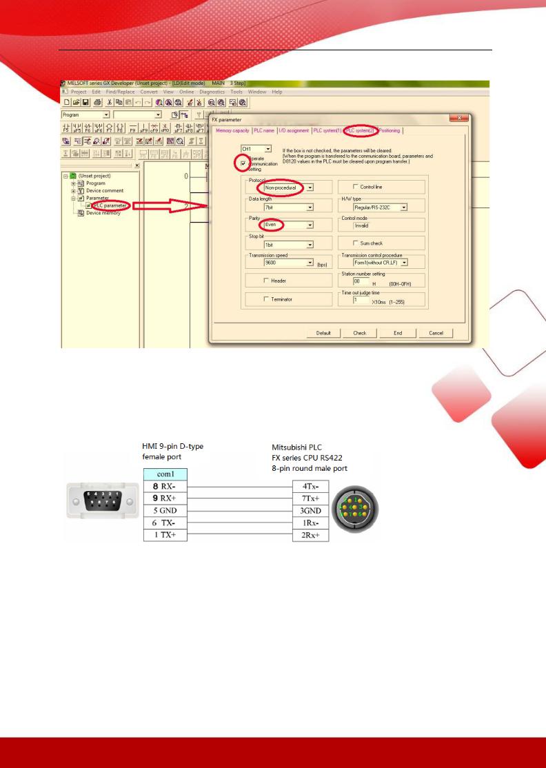
2.4 .3 Cable making
(a) FX3U\3G series PLC RS422:
2.4 .4 Device address
PLC address |
Range |
Type |
Explanation |
X |
0~177 |
Bit |
External input terminal |
|
|
|
|
Y |
0~177 |
Bit |
External output terminal |
|
|
|
|
M |
0~8255 |
Bit |
Internal auxiliary coil |
|
|
|
|
|
|
18 |
|

S |
0~999 |
Bit |
Stepper coil |
|
|
|
|
T |
0~255 |
Bit |
Timer |
|
|
|
|
C |
0~255 |
Bit |
Counter |
|
|
|
|
C16 |
0~199 |
Word/DWord |
16-bit counter |
|
|
|
|
C32 |
200~255 |
DWord |
32-bit counter |
|
|
|
|
D |
0~8255 |
Word/DWord |
Data register |
|
|
|
|
T |
0~255 |
Word/DWord |
Timer current value |
|
|
|
|
X |
0~177 |
Word/DWord |
Used as data register |
|
|
|
|
Y |
0~177 |
Word/DWord |
Used as data register |
|
|
|
|
M |
0~8255 |
Word/DWord |
Used as data register |
|
|
|
|
S |
0~999 |
Word/DWord |
Used as data register |
|
|
|
|
19

2.5 Mitsubishi FX BD series PLC (RS232/485)
2.5.1 Device type
|
|
Series |
|
|
CPU |
|
|
Connected |
|
|
Port |
|
|
Cable |
|
|
PLC type in |
|
|
|
|
|
|
|
module |
|
|
|
|
|
|
Touchwin software |
|
||||
|
|
|
|
|
|
|
|
|
|
|
|
|
|
|
|
|
||
|
|
|
|
|
FX0N/1N/2 |
|
232-BD |
|
RS232 |
|
Fig1 |
|
|
|
||||
|
|
|
|
|
|
|
|
|
|
|
|
|
||||||
|
|
FX |
|
N |
|
|
|
|
|
|
|
|
|
|
Mitsubishi FX |
|||
|
|
|
FX1S |
|
|
|
|
|
|
|
|
|
|
BD(232\485) |
||||
|
|
|
|
|
|
|
|
|
|
|
|
|
||||||
|
|
|
|
|
|
|
|
|
|
|
|
|
|
|
||||
|
|
|
|
|
FX3U/3G |
|
485-BD |
|
RS485 |
|
Fig2 |
|
|
|
||||
|
|
|
|
|
|
|
|
|
|
|
|
|
|
|
|
|
||
|
|
|
|
|
|
|
|
|
|
|
|
|
|
|
|
|
||
Note: |
|
|
|
|
|
|
|
|
|
|
|
|
|
|
|
|||
1.Do not hot plug the device!
2.The driver of 485-BD supports multi-station.
2.5.2 Parameters
HMI settings:
Paramete |
Recommend settings |
Choices of settings |
Notes |
rs |
|
|
|
PLC type |
Mitsubishi FX BD(232\485) |
|
|
|
|
|
|
Data bit |
7 |
|
|
|
|
|
|
Stop bit |
1 |
|
|
|
|
|
|
Parity |
Even parity |
|
|
|
|
|
|
Baud rate |
9600 |
9600/19200/38400/56000/57600 |
|
|
|
/ |
|
|
|
115200/187500 |
|
|
|
|
|
Station |
0 |
0~255 |
|
no. |
|
|
|
|
|
|
|
The default paramreters of Mitsubishi FX BD (232/485): 9600, 7, 1, even parity, station no.0 PLC settings:
20
Note:
1.Please choose RS232 as H/W type when using 232-BD.
2.Please re-power on the PLC after changing the parameters.
2.5.3Cable making
(a)FX series PLC RS232-BD:
Fig1
(b) FX series PLC RS485-BD:
21
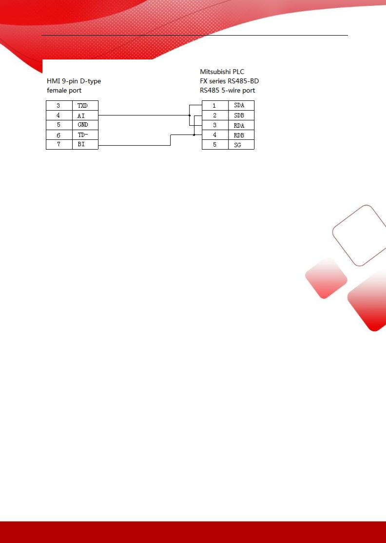
Fig2
2.5.3 Device address
PLC |
Range |
Data type |
Explanation |
address |
|
|
|
X |
0~177 |
Bit |
External input terminal |
|
|
|
|
Y |
0~177 |
Bit |
External output terminal |
|
|
|
|
M |
0~8255 |
Bit |
Internal auxiliary coil |
|
|
|
|
S |
0~999 |
Bi |
Stepper coil |
|
|
|
|
T |
0~255 |
Bit |
Timer |
|
|
|
|
C |
0~255 |
Bit |
Counter |
|
|
|
|
C16 |
0~199 |
Word/DWord |
16-bit counter |
|
|
|
|
C32 |
200~255 |
DWord |
32-bit counter |
|
|
|
|
D |
0~8255 |
Word/DWord |
Data register |
|
|
|
|
T |
0~255 |
Word/DWord |
Current value |
|
|
|
|
X |
0~177 |
Word/DWord |
Used as data register |
|
|
|
|
Y |
0~177 |
Word/DWord |
Used as data register |
|
|
|
|
M |
0~8255 |
Word/DWord |
Used as data register |
|
|
|
|
S |
0~999 |
Word/DWord |
Used as data register |
|
|
|
|
22
2.6 Mitsubishi Q series PLC
2.6 .1 Model
MELSEC-Q series include the CPU unit of Q00, Q01, Q00U and so on. They can connect to the HMI via programmable port or communication module (QJ71C24N).
|
Series |
|
|
CPU |
|
|
Connected module |
|
|
Port |
|
|
Cable |
|
|
Device |
|
|
|
|
|
|
|
|
|
|
|
making |
|
|
|
||||||
|
|
|
|
|
|
|
|
|
|
|
|
|
|
|
|
|
|
|
|
|
|
|
Q00 |
|
CPU |
direct |
|
|
|
|
|
|
|
Mitsubishi Q |
|||
|
|
|
|
Q01 |
|
|
RS232 |
|
Fig 1 |
|
||||||||
|
|
|
|
|
connection |
|
|
|
|
|
series |
|||||||
|
|
|
|
Q00U |
|
|
|
|
|
|
|
|
|
|
||||
|
|
|
|
|
|
|
|
|
|
|
|
|
|
|
|
|
||
|
|
|
|
|
|
|
|
|
|
|
|
|
|
|
|
|
|
|
|
Q |
|
Q00J Q00 |
|
|
|
|
|
|
|
|
|
|
|
|
|
||
|
|
Q01 Q02H |
|
|
|
|
|
RS232 |
|
Fig 2 |
|
|
|
|||||
|
|
|
|
|
|
|
|
|
|
|
|
|
||||||
|
|
|
|
|
Serial communication |
|
|
|
|
|
|
|
Mitsubishi Q |
|||||
|
|
|
|
Q06H Q12H |
|
|
|
|
|
|
|
|
||||||
|
|
|
|
module QJ71C24 |
|
|
|
|
|
|
|
series |
||||||
|
|
|
|
|
|
|
|
|
|
|
||||||||
|
|
|
|
Q25H Q12PH |
|
|
|
|
|
RS422 |
|
Fig 3 |
|
|
|
|||
|
|
|
|
|
|
|
|
|
|
|
|
|
|
|
||||
|
|
|
|
Q25PH |
|
|
|
|
|
|
|
|
|
|
|
|
|
|
|
|
|
|
|
|
|
|
|
|
|
|
|
|
|
|
|
|
|
2.6.2 Parameters
HMI settings:
Parameter |
Recommend |
Choices of settings |
Item |
|
setting |
|
|
PLC type |
Q series |
|
|
|
|
|
|
Data bit |
8 |
7 or 8 |
|
|
|
|
|
Stop bit |
1 |
1 or 2 |
|
|
|
|
|
Parity |
Odd parity |
Even/odd/no parity |
|
|
|
|
|
Baud rate |
19200 |
4800/9600/19200/38400/56000/57600/115200/187500 |
|
|
|
|
|
Station |
0 |
0~255 |
|
No. |
|
|
|
|
|
|
|
The default parameter of Q series PLC: 19200, 8, 1, odd parity, station No.0.
PLC settings:
1. Q01\Q00 PLC:
23

2 QJ71C24N serial port module
QJ71C24N can connect to CPU and communicate with other devices. Such as Q02CPU, the settings are as the following:
PLC software version v8.26
(a) Double click PLC parameter, choose I/O assignment:
(b) Change the type of item1 to intelli.
(c) Click “switch setting” :
24

(d) Set the parameter as the following window:
(e) Click End button to finish the settings, then repower on the PLC.
PLC software version v8.8:
For QJ71C24 module RS232, please set the parameter of CH1:
25

For QJ71C24 module RS422, please set the parameter of CH2:
2.6.3 Cable making
(a) Q series PLC CPU unit, RS232 port:
Fig1
26

(b) Q series PLC uses QJ71C24N module RS232:
Fig2
(c) Q series PLC uses QJ71C24 module RS422:
Fig3
2.6.4 Device address
PLC address |
Range |
Data type |
Explanation |
X |
0~177 |
Bit |
External input coil |
|
|
|
|
Y |
0~177 |
Bit |
External output coil |
|
|
|
|
M |
0~8255 |
Bit |
Internal coil |
|
|
|
|
S |
0~999 |
Bit |
Stepper coil |
|
|
|
|
T |
0~255 |
Bit |
Timer |
|
|
|
|
C |
0~255 |
Bit |
Counter |
|
|
|
|
C16 |
0~199 |
Word/DWord |
16-bit counter |
|
|
|
|
C32 |
200~255 |
DWord |
32-bit counter |
|
|
|
|
D |
0~8255 |
Word/DWord |
Data register |
|
|
|
|
T |
0~255 |
Word/DWord |
Current value |
|
|
|
|
X |
0~177 |
Word/DWord |
Data register |
|
|
|
|
|
|
|
27 |

Y |
0~177 |
Word/DWord |
Data register |
|
|
|
|
M |
0~8255 |
Word/DWord |
Data register |
|
|
|
|
S |
0~999 |
Word/DWord |
Data register |
|
|
|
|
28

2.7 Siemens S7-200 series PLC
2.7.1Model
Seris |
|
CPU |
|
Connected module |
|
Port |
|
Cable |
|
Device |
|
|
CPU212 |
|
|
|
|
|
|
|
|
|
|
CPU221 |
|
Connect CPU RS485 port |
|
|
|
|
|
Siemens |
S7-200 |
|
CPU222 |
|
|
RS485 |
|
Fig 1 |
|
||
|
|
directly |
|
|
|
S7-200 |
||||
|
|
CPU224 |
|
|
|
|
|
|
||
|
|
|
|
|
|
|
|
|
|
|
|
|
CPU226 |
|
|
|
|
|
|
|
|
|
|
|
|
|
|
|
|
|
|
|
S7-200 |
|
Smart series |
|
CPU directly connect |
|
RS485 |
|
Fig1 |
|
Siemens |
smart |
|
|
|
|
|
S7-200 |
||||
|
|
|
|
|
|
|
|
|
||
|
|
|
|
|
|
|
|
|
|
|
2.7.2 Parameters
HMI:
Parameters |
Recommend |
Choices of settings |
Item |
|
settings |
|
|
PLC type |
S7-200 |
|
|
|
|
|
|
Port |
RS485 |
|
|
|
|
|
|
Data bit |
8 |
|
|
|
|
|
|
Stop |
1 |
|
|
|
|
|
|
Parity |
Even parity |
|
|
|
|
|
|
Baud rate |
9600 |
9600/19200/187500 |
|
|
|
|
|
Station no. |
2 |
|
Must use recommend |
|
|
|
settings |
|
|
|
|
The default communication parameters of Siemens S7-200 series PLC: 9600, 8, even parity, station No.2.
PLC settings:
29

Notes:
1.Siemens PLC has 3 kinds of registers: 8-bitVB, 16-bit VW and 32-bit VD.
2.The space of registers are overlapped, the address of VW must be even numbers, for example: VW0 VW2…., the address of VD must be the multiple of 4, such as VD0 VD4
VD8…..
3 For Data block PSW single word → VW single word: as the high byte and low byte problem, the received data maybe dislocated, please use register copy function.
4 For data block PSW single word → VD double words: as the unit is different, cannot trasfer the data like this, please use register copy function.
2.7.3 Cable making
HMI connects to S7-200 via RS485:
Fig1
2.7.4 Device address
SIMATIC S7-200 series
30

PLC address |
Range |
Data type |
Explanation |
VB |
0~4095 |
Byte |
variable byte data register |
|
|
|
|
VW |
0~4095 |
Word |
variable word data register |
|
|
|
|
VD |
0~4095 |
DWord |
variable double word data register |
|
|
|
|
IB |
0~15 |
Byte |
External input byte reflection register |
|
|
|
|
IW |
0~15 |
Word |
External input word reflection register |
|
|
|
|
ID |
0~15 |
DWord |
External input double words reflection |
|
|
|
register |
|
|
|
|
QB |
0~15 |
Byte |
External output byte reflection register |
|
|
|
|
QW |
0~15 |
Word |
External output word reflection register |
|
|
|
|
QD |
0~15 |
DWord |
External output double words reflection |
|
|
|
register |
|
|
|
|
MB |
0~31 |
Byte |
Internal auxiliary byte register |
|
|
|
|
MW |
0~31 |
Word |
Internal auxiliary word register |
|
|
|
|
MD |
0~31 |
DWord |
Internal auxiliary double words register |
|
|
|
|
SMB |
0~299 |
Byte |
Internal special auxiliary byte register |
|
|
|
|
SMW |
0~299 |
Word |
Internal special auxiliary word register |
|
|
|
|
SMD |
0~299 |
DWord |
Internal special auxiliary double words |
|
|
|
register |
|
|
|
|
SB |
0~31 |
Byte |
Special auxiliary byte register |
|
|
|
|
SW |
0~31 |
Word |
Special auxiliary word register |
|
|
|
|
SD |
0~31 |
DWord |
Special auxiliary double words register |
|
|
|
|
T |
0~255 |
Word |
Register |
|
|
|
|
C |
0~255 |
Word |
Register |
|
|
|
|
M |
0~31 |
Bit |
Bit register |
|
|
|
|
V |
0~4095 |
Bit |
Variable register |
|
|
|
|
I |
0~15 |
Bit |
External input coil |
|
|
|
|
Q |
0~15 |
Bit |
External output coil |
|
|
|
|
SM |
0~299 |
Bit |
Special relay |
|
|
|
|
S |
0~31 |
Bit |
Sequence relay |
|
|
|
|
T |
0~255 |
Bit |
Timer |
|
|
|
|
C |
0~255 |
Bit |
Counter |
|
|
|
|
31

2.8 Siemens S7-300/400 series PLC
2.8.1 Model
SIMATIC S7-300/400 PLC (connect to CPU directly)
Series |
|
CPU |
|
Connected module |
|
Port |
|
Cable |
|
Device |
S7-300 |
|
CPU312 CPU314 |
|
|
|
|
|
|
|
Siemens SIMATIC |
|
|
CPU315 |
|
RS485 port of CPU |
|
|
|
|
|
|
|
|
|
|
RS485 |
|
fig 1 |
|
S7-300/400 |
||
|
|
|
|
|
|
|
|
|||
S7-400 |
|
CPU412-1 CPU412-2 |
|
|
|
|
|
|||
|
|
|
|
|
|
|
|
PLC |
||
|
|
CPU414-2 |
|
|
|
|
|
|
|
|
|
|
|
|
|
|
|
|
|
|
|
|
|
|
|
|
|
|
|
|
|
|
2.8.2 Parameters
HMI settings:
Parameter |
Recommend |
Choice of settings |
Note |
|
|
settings |
|
|
|
PLC type |
S7-300/400 |
|
|
|
|
|
|
|
|
Port |
RS485 |
|
|
|
|
|
|
|
|
Data bit |
8 |
7 or 8 |
|
|
|
|
|
|
|
Stop bit |
1 |
1 or 2 |
|
|
|
|
|
|
|
Parity |
Even parity |
Even/odd/no parity |
|
|
|
|
|
|
|
Baud rate |
19200 |
4800/38400/9600/115200/19200/187500 |
|
|
|
|
|
|
|
Station |
2 |
|
Please |
use |
no. |
|
|
recommend settings |
|
|
|
|
|
|
The default parameters of Siemens S7-300\400: 19200, 8, even parity, station No.2.
PLC settings:
32
Communication notes for S7-300:
1. Siemens baud rate must set to 19200 kbps; don’t set the parameters of PG/PC adapter. 2. Don’t modify the “panel station no.” in the Touchwin software.
33

3.Cable: no need PG/PC adapter
4.Please define the DB register in the PLC when testing the communication.
5.Please note that the port will be operated in PLC program by accident.
6.The default station No. of S7-300 is 2, please don’t modify it.
Example: MPI port of S7-300 connects to HMI, the PLC connects to SCADA software via Ethernet module, PLC station no. is 8, module station no. is 3, HMI station no. is 0. The result is that communication between SCADA and PLC will be cut off. Because the HMI cannot find other devices and modules cannot be inserted in. please change the PLC station no. to 2. These devices can form a loop:
2.8.3 Cable making
HMI connects to S7-300/400 via RS485:
34

|
|
SIEMENS PLC |
||
HMI 9-pin female port |
S7-200/300/400 |
|||
PPI 9-pin male port |
||||
|
|
|||
Pin |
Name |
Pin |
Name |
|
4 |
AI |
3 |
A |
|
5 |
GND |
8 |
B |
|
7 |
BI |
5 |
GND |
|
Fig1
2.8.4 Device address
SIMATIC S7-300/400
PLC type |
Range |
Data type |
Explanation |
I |
0~9999 |
Byte/Word/DWord |
External input register |
|
|
|
|
Q |
0~9999 |
Byte/Word/DWord |
External output register |
|
|
|
|
M |
0~9999 |
Byte/Word/DWord |
Internal auxiliary register |
|
|
|
|
DB0~DB20 |
0~9999 |
Byte/Word/DWord |
Data register |
|
|
|
|
I |
0~9999 |
Bit |
External input coil |
|
|
|
|
Q |
0~9999 |
Bit |
External output coil |
|
|
|
|
M |
0~9999 |
Bit |
Internal auxiliary relay |
|
|
|
|
DB0~DB20 |
0~9999 |
Bit |
Internal auxiliary relay |
|
|
|
|
35

2.9 OMRON SYSMAC series PLC
OMRON CPM1A, CQM1-CPU series CPU cannot support RS232. It can connect to the Touchwin HMI via
CPM1-CIF01 adapter and modules including C500-LK203, C120-LK201-V1, C500-LK201-V1. The PLC uses Hostlink protocol when communicating. Please change the PLC startup choice to MONITOR RUN.
2.9.1 Device model
|
|
|
|
|
|
|
|
|
|
|
|
|
|
|
|
|
|
|
|
|
The PLC |
|
|
|
|
|||
|
Series |
|
|
CPU |
|
|
Connected |
|
|
Communication |
|
|
Cable |
|
|
device in |
|
|
|
|
||||||||
|
|
|
|
|
module |
|
|
mode |
|
|
|
|
TouchWin |
|
|
|
|
|||||||||||
|
|
|
|
|
|
|
|
|
|
|
|
|
|
|
|
|
|
|
|
|||||||||
|
|
|
|
|
|
|
|
|
|
|
|
|
|
|
|
|
|
|
|
|
|
|
|
|
|
|
|
|
|
CP |
|
CP1E-30N |
|
CPU |
direct |
|
RS232 |
|
Fig 1 |
|
|
|
|
|
|
|
|
|
|||||||||
|
|
|
|
CP1H |
|
connection |
|
|
|
|
|
|
|
|
|
|
|
|
|
|||||||||
|
|
|
|
|
|
|
|
|
|
|
|
|
|
|
|
|
|
|
|
|
|
|
|
|||||
|
|
|
|
CP1L |
|
|
|
|
|
|
|
|
|
|
|
|
|
|
|
|
|
|
|
|
|
|||
|
|
|
|
|
Module |
|
|
|
RS485 |
|
Fig 2 |
|
|
|
|
|
|
|
|
|
||||||||
|
|
|
|
|
|
|
|
|
CP1W-CIF11 |
|
|
|
|
|
|
|
|
|
|
|
||||||||
|
|
|
|
|
|
|
|
|
|
|
|
|
|
|
|
|
|
|
|
|
|
|
|
|
|
|||
|
|
|
|
|
|
|
|
|
|
|
|
|
|
|
|
|
|
|
|
|
|
|
|
|
|
|
|
|
|
|
|
|
|
|
|
|
|
Module |
|
|
|
RS422 |
|
Fig 3 |
|
|
|
|
|
|
|
|
|
||||
|
|
|
|
|
|
|
|
|
CP1W-CIF11 |
|
|
|
|
|
|
|
|
|
|
|
||||||||
|
|
|
|
|
|
|
|
|
|
|
|
|
|
|
|
|
|
|
|
|
|
|
|
|
|
|||
|
|
|
|
|
|
|
|
|
|
|
|
|
|
|
|
|
|
|
|
|
|
|
|
|
|
|
|
|
|
CJ |
|
CJ1 |
|
|
|
|
|
|
|
|
|
|
|
|
|
|
|
|
|
|
|
|
|
||||
|
|
|
|
CJ1G-CPU44 |
|
CPU direct |
|
RS232 |
|
Fig 1 |
|
|
|
|
|
|
|
|
|
|||||||||
|
|
|
|
CJ1G-CPU45 |
|
connection |
|
|
|
|
|
|
|
|
|
|
|
|||||||||||
|
|
|
|
|
|
|
|
|
|
|
|
|
|
|
|
|
|
|
|
|
|
|||||||
|
|
|
|
CJ2M-CPU11 |
|
|
|
|
|
|
|
|
|
|
|
|
|
Omron |
|
|
||||||||
|
|
|
|
|
|
|
|
|
|
|
|
|
|
|
|
|
|
|
|
CP/CJ/CS |
|
|
||||||
|
CS1 |
|
CS1H-CPU63/64/65/66/67 |
|
|
|
|
|
|
|
|
|
|
|
|
|
|
|
|
|||||||||
|
|
|
|
CS1G-CPU42/43/44/45 |
|
|
|
|
|
|
|
|
|
|
|
|
|
|
|
|
|
|
|
|
|
|||
|
|
|
|
CS1G-CPU42H |
|
|
|
|
|
|
|
|
|
|
|
|
|
|
|
|
|
|
|
|
|
|||
|
|
|
|
CS1G-CPU43H |
|
|
|
|
|
|
|
|
|
|
|
|
|
|
|
|
|
|
|
|
|
|||
|
|
|
|
CS1G-CPU44H |
|
CPU direct |
|
|
|
|
|
|
|
|
|
|
|
|
|
|
|
|
|
|||||
|
|
|
|
CS1G-CPU45H |
|
|
RS232 |
|
Fig 1 |
|
|
|
|
|
|
|
|
|
||||||||||
|
|
|
|
|
connection |
|
|
|
|
|
|
|
|
|
|
|
||||||||||||
|
|
|
|
CS1H-CPU63H |
|
|
|
|
|
|
|
|
|
|
|
|
|
|
|
|
|
|
||||||
|
|
|
|
|
|
|
|
|
|
|
|
|
|
|
|
|
|
|
|
|
|
|
|
|
||||
|
|
|
|
CS1H-CPU64H |
|
|
|
|
|
|
|
|
|
|
|
|
|
|
|
|
|
|
|
|
|
|||
|
|
|
|
CS1H-CPU65H |
|
|
|
|
|
|
|
|
|
|
|
|
|
|
|
|
|
|
|
|
|
|||
|
|
|
|
CS1H-CPU66H |
|
|
|
|
|
|
|
|
|
|
|
|
|
|
|
|
|
|
|
|
|
|||
|
|
|
|
CS1H-CPU67H |
|
|
|
|
|
|
|
|
|
|
|
|
|
|
|
|
|
|
|
|
|
|||
|
|
|
|
|
|
|
|
|
|
|
|
|
|
|
|
|
|
|
|
|
|
|
|
|
|
|
||
|
|
|
|
|
|
|
|
|
|
|
|
|
|
|
|
|
|
|
|
|
|
|
|
|
|
|||
|
|
|
|
|
|
|
|
|
|
|
|
|
|
|
|
|
|
|
|
|
|
|
|
The PLC |
|
|||
|
Series |
|
|
CPU |
|
|
|
Connected module |
|
|
Communication |
|
|
Cable |
|
|
device in |
|
||||||||||
|
|
|
|
|
|
|
|
mode |
|
|
|
|
TouchWin |
|
||||||||||||||
|
|
|
|
|
|
|
|
|
|
|
|
|
|
|
|
|
|
|
|
|
||||||||
|
|
|
|
|
|
|
|
|
|
|
|
|
|
|
|
|
|
|
|
|
|
|
|
|
|
|
|
|
|
|
|
|
|
|
|
|
36 |
|
|
|
|
|
|
|
|
|
|
|
|
|
|
|
|
|
|
|
|

C |
C200HE |
CPU direct connection |
|
|
|
|
C200HX |
|
|
|
|
|
|
|
|
|
|
|
|
|
|
|
|
|
C1000HF |
C500-LK203 (communication |
|
|
|
|
|
module) |
|
|
|
|
|
|
|
|
|
|
|
C120-LK201-V1(communication |
RS232 |
Fig 1 |
|
|
|
module) |
|
||
|
|
|
|
|
|
|
|
|
|
|
|
|
C2000 |
C500-LK201-V1(communication |
|
|
|
|
module) |
|
|
|
|
|
|
|
|
|
|
|
|
|
|
|
|
|
|
C500-LK203(communication |
|
|
Omron |
|
|
|
|
|
|
|
|
module) |
|
|
CPM/CQM |
|
|
|
|
|
|
CPM |
CPM2A |
|
|
|
|
|
CPM2AE |
CPU direct connection |
|
|
|
|
CPM2AH-40CDR-A |
|
|
|
|
|
|
|
|
|
|
|
CPM1H |
|
|
|
|
|
|
|
|
|
|
|
CPM1A |
OMRON CIF01 (RS232) |
RS232 |
Fig 1 |
|
|
|
|
|
||
|
|
Communication adapter |
|
|
|
|
|
|
|
|
|
CQM |
CQM1H-CPU21 |
CPU direct connection |
|
|
|
|
|
|
|
|
|
|
|
|
|
|
|
|
CQM1-CPU |
OMRON CIF01 (RS232) |
|
|
|
|
|
Communication adapter |
|
|
|
|
|
|
|
|
|
2.9.2 Parameters
HMI:
The default parameters of OMRON CP/CJ/CS series PLC: 9600, 7, 2, even parity, station no.0. The default parameters of OMRON CPM/CQM series PLC: 9600, 7, 2, even parity, station no.0.
Parameter |
Recommended settings |
Choices of settings |
Notes |
PLC type |
OMRON CPM/CQM series |
OMRON CP/CJ/CS series |
|
|
OMRON CP/CJ/CS series |
OMRON CPM/CQM series |
|
|
|
|
|
Port |
RS232 |
RS232/RS485 |
|
|
|
|
|
Data bit |
7 |
7 or 8 |
|
|
|
|
|
Stop bit |
2 |
1 or 2 |
|
|
|
|
|
Parity |
Even parity |
Even/odd/ no parity |
|
|
|
|
|
Baud rate |
9600 |
4800/38400/9600/115200 |
|
|
|
/19200/187500 |
|
|
|
|
|
Station no. |
0 |
0~255 |
|
|
|
|
|
37

2.9.3 Cable making
(a) CPU RS232 port:
|
|
OMROM PLC |
|
|
|
CPU CPM1-CIF01/C500-LK203 |
|
|
|
C120-LK201-V1/C500-LK203 |
|
HMI 9-pin female port |
RS232 9-pin male port |
||
Pin |
Name |
Pin |
Name |
2 |
RXD1 |
3 |
RD |
3 |
TXD1 |
2 |
SD |
5 |
GND |
9 |
GND |
|
|
4 |
RTS |
|
|
5 |
CTS |
Fig1
(b) Through module CP1W-CIF11 RS485:
Fig2
Note: If OMRON RS485 module CPIW-CIF11 uses 485-2 connection mode, turn OFF the SW1 switch on the module, turn ON SW2, 3, 5, 6. SW4 is selectable.
(c) Through the module CP1W-CIF11 RS422:
Fig3
38

Note: If OMRON RS485 module CP1W-CIF11 uses RS422 connection mode, turn OFF the SW1~6 on the module.
2.9.4 Device address
(a) SYSMAC CPM/CQM series
|
PLC address |
Range |
Data type |
Explanation |
|
|
IR |
0~65535 |
Bit |
I/O and internal relay |
|
|
|
|
|
|
|
|
SR |
244~65535 |
Bit |
Relay |
|
|
|
|
|
|
|
|
HR |
0~65535 |
Bit |
Holding relay |
|
|
|
|
|
|
|
|
AR |
0~65535 |
Bit |
Auxiliary relay |
|
|
|
|
|
|
|
|
LR |
0~65535 |
Bit |
Link relay |
|
|
|
|
|
|
|
|
PV |
0~65535 |
Bit |
Current value of timer and |
|
|
|
|
|
counter |
|
|
|
|
|
|
|
|
TC |
0~65535 |
Bit |
Timer and counter |
|
|
|
|
|
|
|
|
IR |
0~65535 |
Word/DWor |
Register |
|
|
|
|
d |
|
|
|
|
|
|
|
|
|
SR |
244~65535 |
Word/DWor |
Register |
|
|
|
|
d |
|
|
|
|
|
|
|
|
|
HR |
0~65535 |
Word/DWor |
Register |
|
|
|
|
d |
|
|
|
|
|
|
|
|
|
AR |
0~65535 |
Word/DWor |
Register |
|
|
|
|
d |
|
|
|
|
|
|
|
|
|
LR |
0~65535 |
Word/DWor |
Register |
|
|
|
|
d |
|
|
|
|
|
|
|
|
|
PV |
0~65535 |
Word/DWor |
Register |
|
|
|
|
d |
|
|
|
|
|
|
|
|
|
TC |
0~65535 |
Word/DWor |
Register |
|
|
|
|
d |
|
|
|
|
|
|
|
|
|
DM |
0~65535 |
Word/DWor |
Data register (single/double |
|
|
|
|
d |
words) |
|
|
|
|
|
|
|
(b) SYSMAC CP/CJ/CS series |
|
|
|
||
|
|
|
|
|
|
|
PLC address |
Range |
Data type |
Explanation |
|
|
CIO |
0~9999 |
Bit |
|
|
|
|
|
|
|
|
|
D |
0~99999 |
Bit |
|
|
|
|
|
|
|
|
|
H |
0~9999 |
Bit |
|
|
|
|
|
|
|
|
|
W |
0~9999 |
Bit |
|
|
|
|
|
|
|
|
|
A |
0~9999 |
Bit |
|
|
|
|
|
|
|
|
|
T |
0~9999 |
Bit |
Timer |
|
|
|
|
|
|
|
|
C |
0~9999 |
Bit |
Counter |
|
|
|
|
|
|
|
|
|
|
39 |
|
|

CIO |
0~9999 |
Word/DWor |
Register |
|
|
d |
|
|
|
|
|
D |
0~99999 |
Word/DWor |
Register |
|
|
d |
|
|
|
|
|
H |
0~9999 |
Word/DWor |
Register |
|
|
d |
|
|
|
|
|
W |
0~9999 |
Word/DWor |
Register |
|
|
d |
|
|
|
|
|
A |
0~9999 |
Word/DWor |
Register |
|
|
d |
|
|
|
|
|
T |
0~9999 |
Word/DWor |
Register |
|
|
d |
|
|
|
|
|
C |
0~9999 |
Word/DWor |
Register |
|
|
d |
|
|
|
|
|
40

2.10 Koyo S series PLC
Koyo KOSTA-S and Direct-Logic series PLC
2.10.1 Device model
(a) Kostac S series SH\SM\SN PLC (direct connect to the CPU module)
Series |
|
CPU |
|
Connected module |
|
Port |
|
Cable |
|
Device |
|
|
|
|
|
|
|
|
|
|
|
SH series |
|
SH-48RS |
|
CPU |
|
|
|
|
|
|
|
|
|
|
|
|
|
|
|
|
|
SM series |
|
SM24-T |
|
|
RS232 |
|
Fig1 |
|
|
|
|
|
|
|
|
|
|
||||
|
|
|
|
|
|
|
|
|
|
|
SN series |
|
|
|
|
|
|
|
|
|
Koyo S series |
|
|
|
|
|
|
|
|
|
|
|
SU-6 |
|
|
|
CPU |
|
RS232 |
|
Fig1 |
|
|
|
|
|
|
|
|
|
||||
|
|
|
|
|
|
|
|
|
|
|
SU-6B |
|
|
|
|
RS232 |
|
Fig1 |
|
|
|
|
|
|
|
|
|
|
|
|||
|
|
|
|
|
|
|
|
|
|
|
|
|
|
|
|
RS422 |
|
Fig3 |
|
|
|
|
|
|
|
|
|
|
|
|
||
|
|
|
|
|
|
|
|
|
|
|
Note: Koyo SH-48RS doesn’t have Run, Stop switch, but only have one AMP port.
(b) Koyo Kostac S series SG-8, SU-5, SU-6, SR-21, SR-22… PLC (use communication module)
CPU |
|
Connected module |
|
|
Port |
|
Cable |
|
Device |
|
|
|
|
|
|
|
|
|
|
SG-8 |
G01-DM communication unit |
|
|
RS232 |
|
Fig 1 |
|
|
|
|
|
|
|
|
|
|
|||
|
|
RS422 |
|
Fig 3 |
|
|
|||
|
|
|
|
|
|
|
|
||
|
|
|
|
|
|
|
|
|
|
SU-5 |
U01-DM communication unit |
|
|
RS232 |
|
Fig 1 |
|
Koyo S series |
|
|
|
|
|
|
|
|
|||
SU-6 |
|
U01-DM communication unit |
|
|
|
|
|||
|
|
|
|
|
|
|
|
||
|
|
|
|
|
|
|
|
|
|
SR-21 |
|
E-02DM-R1 communication unit |
|
|
RS422 |
|
Fig 3 |
|
|
|
|
|
|
|
|
|
|
||
SR-22 |
|
|
|
|
|
|
|
||
|
|
|
|
|
|
|
|
|
|
|
|
|
|
|
|
|
|
|
|
(c) Koyo Direct Logic series DL05, DL250…PLC (connect to CPU directly)
Series |
|
CPU |
|
Connected module |
|
Port |
|
Cable |
|
|
Device |
|
|
|
|
|
|
|
|
|
|
|
|
|
|
DL05 |
|
|
|
|
|
|
|
|
|
|
|
DL105 |
|
|
|
|
|
|
|
|
|
|
|
DL230 |
|
Connect to RJ-11port(RS232) of CPU |
|
|
|
|
|
|
|
|
|
DL240 |
|
|
RS232 |
|
Fig 2 |
|
|
|
|
Direct Logic |
|
|
|
|
|
|
|
Koyo S series |
|||
|
DL250 |
|
|
|
|
|
|
|
|
||
|
|
|
|
|
|
|
|
|
|
|
|
|
|
DL350 |
|
|
|
|
|
|
|
|
|
|
|
DL450 |
|
|
|
|
|
|
|
|
|
|
|
|
|
|
|
|
|
|
|
|
|
|
|
DL250 |
Connect to the port of CPU |
|
RS422 |
|
Fig 3 |
|
|
|
|
|
|
|
|
|
|
|
|
|
|
|
|
41

|
DL430 |
Connect to the port of CPU |
|
|
|
|
DL440 |
|
RS232 |
Fig 2 |
|
|
DL450 |
|
|
||
|
|
|
|
|
|
|
DL350 |
|
|
|
|
|
|
|
|
|
|
Note: port2 of DL250CPU has RS232 and RS422; please indentify them when making the cable.
2.10.2 Parameters
HMI:
Parameter |
Recommend settings |
Choices of settings |
Notes |
PLC |
Koyo S series PLC |
|
|
|
|
|
|
Port |
RS232 |
RS232 or RS422 |
|
|
|
|
|
Data bit |
8 |
7 or 8 |
|
|
|
|
|
Stop bit |
1 |
1 or 2 |
|
|
|
|
|
Parity |
Odd parity |
Even/odd/no parity |
|
|
|
|
|
Baud rate |
9600 |
4800/38400/9600/115200/19200/187500 |
|
|
|
|
|
Station no. |
0 |
0~255 |
|
|
|
|
|
The default communication parameters of Koyo S series PLC: 9600, 8, 1, odd parity, station no.0.
PLC:
42
Note: 1. Koyo K protocol cannot modify station no., the station no. is 0 in the HMI.
2.The register address starts from R2000.
2.10.3Cable making
(a) RS232 25-pin port on CPU or communication unit:
Fig1
RJ-11 6-pin RS232 female port on the CPU:
6 5 4 3 2 1
Fig2
RS422 connection:
43

Fig3
2.10.4 Device address
PLC address |
Range |
Data type |
Explanation |
M |
0~777 |
Bit |
Internal auxiliary coil |
|
|
|
|
I |
0~777 |
Bit |
External input coil |
|
|
|
|
Q |
0~777 |
Bit |
External output coil |
|
|
|
|
SP |
0~777 |
Bit |
Internal auxiliary coil |
|
|
|
|
T |
0~777 |
Bit |
Timer |
|
|
|
|
C |
0~777 |
Bit |
Counter |
|
|
|
|
S |
0~777 |
Bit |
Stepper coil |
|
|
|
|
R |
0~41200 |
Word/DWor |
Data register |
|
|
d |
|
|
|
|
|
44

2.11 Koyo DL series PLC
2.11.1 Device type
Koyo Direct Logic series DL05, DL250 PLC (direct connect to CPU)
Series |
|
CPU |
|
Connected |
|
|
Port |
|
Cable |
|
Choose PLC type in |
|
|
|
|
module |
|
|
|
|
|
|
Touchwin software |
|
|
DL05 |
|
|
|
|
|
|
|
|
|
|
|
DL105 |
|
Connect to |
|
|
|
|
|
|
|
|
|
DL230 |
|
CPU RJ-11 |
|
|
RS232 |
|
Fig 1 |
|
|
Direct |
|
DL240 |
|
port |
|
|
|
|
|
|
|
|
DL250 |
|
|
|
|
|
|
|
|
Koyo DL series |
|
Logic |
|
|
|
|
|
|
|
|
|
||
|
DL350 |
|
|
|
|
|
|
|
|
|
|
|
|
|
|
|
|
|
|
|
|
||
|
|
|
|
|
|
|
|
|
|
|
|
|
|
DL430 |
|
Connect |
to |
|
RS422 |
|
Fig 2 |
|
|
|
|
DL440 |
|
CPU com port |
|
|
|
|
|||
|
|
|
|
|
|
|
|
|
|||
|
|
DL450 |
|
|
|
|
|
|
|
|
|
|
|
|
|
|
|
|
|
|
|
|
|
Note: the port2 of DL250 has RS232 and RS422, please indentify the cable connection for them.
2.11.2 Parameters
HMI settings:
Parameter |
Recommend |
Choices of settings |
Note |
s |
settings |
|
|
PLC type |
Koyo DL series |
|
|
|
|
|
|
Port |
RS232 |
RS232/RS422 |
|
|
|
|
|
Data bit |
8 |
7/8 |
|
|
|
|
|
Stop bit |
1 |
1/2 |
|
|
|
|
|
Parity |
Odd parity |
Even /odd /no parity |
|
|
|
|
|
Baud rate |
9600 |
4800/38400/9600/115200/19200/18750 |
|
|
|
0 |
|
|
|
|
|
Station no. |
0 |
0-255 |
|
|
|
|
|
2.11.3 Cable making
RS232 Connection:
45

Fig1
RS422 connection:
Fig2
2.11.4 Device address
Device address |
Range |
Data type |
Explanation |
V |
0 41200 |
Word/DWord |
Data register |
|
|
|
|
C |
0 777 |
Bit |
Counter |
|
|
|
|
X |
0 777 |
Bit |
Input |
|
|
|
|
Y |
0 777 |
Bit |
Output |
|
|
|
|
SP |
0 777 |
Bit |
Auxiliary relay |
|
|
|
|
T |
0 777 |
Bit |
Timer |
|
|
|
|
CT |
0 777 |
Bit |
Counter |
|
|
|
|
S |
0 777 |
Bit |
Auxiliary relay |
|
|
|
|
V |
0.0 41200.15 |
Bit |
Auxiliary relay |
|
|
|
|
46

2.12 Delta DVP series PLC
2.12.1Model
|
Delta DVP series |
CPU |
|
Connected module |
|
Port |
|
Cable |
|
Deivce |
|
ES\EH\EX |
|
|
|
|
RS232 |
|
Fig 1 |
|
|
|
|
|
|
|
|
|
|
|
|
|
|
|
Direct connect to the CPU |
|
RS485 |
|
Fig 2 |
|
Delta DVP series |
||
|
|
|
|
|
|
|
||||
|
|
|
|
|
|
|
|
|
||
|
SS\SA\SC\SX |
|
|
|
RS232 |
|
Fig 1 |
|
||
|
|
|
|
|
|
|
|
|||
|
|
|
|
|
|
|
|
|
|
|
|
|
|
|
RS485 |
|
Fig 2 |
|
|
||
|
|
|
|
|
|
|
|
|
||
|
|
|
|
|
|
|
|
|
|
|
2.12.2 Parameters
HMI:
Parameters |
Recommend settings |
Choices of settings |
Notes |
PLC type |
Delta DVP series |
|
|
|
|
|
|
Port |
RS232 |
RS232 or RS485 |
|
|
|
|
|
Data bit |
7 |
7 or 8 |
|
|
|
|
|
Stop bit |
1 |
1 or 2 |
|
|
|
|
|
Parity |
Even parity |
Even/odd/no parity |
|
|
|
|
|
Baud rate |
9600 |
4800/38400/9600/115200/19200/187500 |
|
|
|
|
|
Station no. |
1 |
0~255 |
|
|
|
|
|
The default communication parameters of Delta DVP series PLC: 9600, 7, 1, even parity, station no.1.
2.12.3 Cable making
(a) The RS232 port on CPU:
Fig 1
47

(b) RS485 port on the CPU:
Fig2
2.12.4 Device address
PLC address |
Range |
Data type |
Explanation |
X |
0~377 |
Bit |
External input coil |
|
|
|
|
Y |
0~377 |
Bit |
External output coil |
|
|
|
|
M |
0~1279 |
Bit |
Internal auxiliary relay |
|
|
|
|
S |
0~1023 |
Bit |
Stepper coil |
|
|
|
|
T |
0~255 |
Bit |
Timer |
|
|
|
|
C |
0~255 |
Bit |
Counter |
|
|
|
|
D |
0~1279 |
Word/DWor |
Data register |
|
|
d |
|
|
|
|
|
TD |
0~255 |
Word/DWor |
Current value of timer |
|
|
d |
|
|
|
|
|
CD |
0~255 |
Word/DWor |
Current value of counter |
|
|
d |
|
|
|
|
|
S |
0~1023 |
Word/DWor |
Data register |
|
|
d |
|
|
|
|
|
X |
0~377 |
Word/DWor |
Data register |
|
|
d |
|
|
|
|
|
Y |
0~377 |
Word/DWor |
Data register |
|
|
d |
|
|
|
|
|
M |
0~127 |
Word/DWor |
Data register |
|
|
d |
|
|
|
|
|
48

2.13 LG Master-K(CPU Direct) series PLC
LG Master-K series PLC support CPU(RS232) and Cnet module communication mode. This chapter will introduce CPU mode.
2.13.1 Device model
|
Series |
|
Connected module |
|
Port |
|
Cable |
|
Device |
|
K80 |
|
CPU |
|
RS232 |
|
Fig 1 |
|
LG Master-K80/120 series |
|
K120 |
|
|
|
|
||||
|
|
|
|
|
|
|
|
|
|
|
|
|
|
|
|
|
|
|
|
Note: before communicating, please write “END” instruction to the PLC. Otherwise, the PLC will report an error and the ERR LED will light.
2.13.2 Parameters
HMI:
Parameters |
Recommend settings |
Choices of settings |
Notes |
PLC type |
LG Master-K80/120 series |
|
|
|
PLC |
|
|
|
|
|
|
Port |
RS232 |
RS232 |
|
|
|
|
|
Dat bit |
8 |
7 or 8 |
|
|
|
|
|
Stop bit |
1 |
1 or 2 |
|
|
|
|
|
Parity |
No parity |
Even/odd/no parity |
|
|
|
|
|
Baud rate |
38400 |
4800/38400/9600/115200/19200/187500 |
|
|
|
|
|
Station no. |
0 |
0~255 |
|
|
|
|
|
The default communication parameters of LG Master K: 38400, 8, 1, no parity, station no.0.
PLC:
49

2.13.3 Cable making
Master-K 80\120 RS232:
Fig1
2.13.4 Device address
LGMaster-K80/120 series PLC
PLC address |
Range |
Data type |
Explanation |
M |
0~9999F |
Bit |
Internal auxiliary relay |
|
|
|
|
L |
0~9999F |
Bit |
Link relay |
|
|
|
|
K |
0~9999F |
Bit |
Holding relay |
|
|
|
|
T |
0~9999 |
Bit |
Timer |
|
|
|
|
C |
0~9999 |
Bit |
Counter |
|
|
|
|
P |
0~9999F |
Bit |
I/O coil |
|
|
|
|
D |
0~9999 |
Word/DWor |
Data register |
|
|
d |
|
|
|
|
|
|
|
50 |
|

TD |
0~9999 |
Word/DWor |
Current value of timer |
|
|
d |
|
|
|
|
|
CD |
0~9999 |
Word/DWor |
Current value of counter |
|
d |
|
|
|
|
|
|
|
|
|
|
S |
0~9999 |
Word/DWor |
Used as register |
|
|
d |
|
|
|
|
|
K |
0~9999 |
Word/DWor |
Used as register |
|
|
d |
|
|
|
|
|
M |
0~9999 |
Word/DWor |
Used as register |
|
|
d |
|
|
|
|
|
L |
0~9999 |
Word/DWor |
Used as register |
|
|
d |
|
|
|
|
|
F |
0~9999 |
Word/DWor |
Used as register |
|
|
d |
|
|
|
|
|
P |
0~9999 |
Word/DWor |
Used as register |
|
|
d |
|
|
|
|
|
51

2.14 LG Master-K(Cnet) series PLC
LG Master-K80/120 series PLC Cnet communication module
LG Master-K series PLC support CPU(RS232) and Cnet expansion port communication mode. This chapter will introduce Cnet mode.
2.14.1 Device model
|
Series |
|
Connected module |
|
Port |
|
Cable |
|
Device |
|
K80 |
|
Cnet communication module |
|
RS232 |
|
Fig 1 |
|
LG Master-K80/120 Cnet series |
|
K120 |
|
|
|
|
|
|
||
|
|
|
RS485 |
|
Fig 2 |
|
|||
|
|
|
|
|
|
|
|||
|
|
|
|
|
|
|
|
|
|
Note:
1.For Master K-cnet communication, turn ON DIP switch 2, turn OFF DIP switch 1. For LG Master KxxxS communication, keep the DIP switch to default settings.
2.LG Master KxxxS CPU only supports RS232 connection. Cnet communication module supports RS232 and RS485 connection.
2.14.2 Parameters
HMI:
Parameters |
Recommend settings |
Choices of settings |
Notes |
PLC type |
LG Master-K80/120 (Cnet series PLC |
|
|
|
|
|
|
Port |
RS232 |
RS232 |
|
|
|
|
|
Data bit |
8 |
7 or 8 |
|
|
|
|
|
Stop bit |
1 |
1 or 2 |
|
|
|
|
|
Parity |
Even parity |
Even/odd/no parity |
|
|
|
|
|
Baud rate |
9600 |
4800/38400/9600/115200 |
|
|
|
/19200/187500 |
|
|
|
|
|
Station no. |
1 |
0~255 |
|
|
|
|
|
The default parameters of LG Master K-cnet : 9600, 8, 1, even parity, station no.1.
PLC:
Notes:
1.Turn on the switch BUILT-IN CNET on the PLC.
2.Choose the correct channel, protocol and mode.
0-RS232 communication:
52
1-RS485 communication:
2.14.3 Cable making
(a) Master K-cnet protocol RS232:
53

Fig 1
(b) Master K-cnet protocol RS485-2:
Fig 2
2.14.4 Device address
LGMaster-K80/120 Cnet series PLC
PLC address |
Range |
|
|
Data type |
Explanation |
M |
0~9999F |
|
Bit |
Internal auxiliary relay |
|
|
|
|
|
|
|
L |
0~9999F |
|
Bit |
Link relay |
|
|
|
|
|
|
|
K |
0~9999F |
|
Bit |
Holding relay |
|
|
|
|
|
|
|
T |
0~9999 |
|
|
Bit |
Timer |
|
|
|
|
|
|
C |
0~9999 |
|
|
Bit |
Counter |
|
|
|
|
|
|
P |
0~9999F |
|
Bit |
I/O coil |
|
|
|
|
|
|
|
D |
0~9999 |
|
|
Word/DWor |
Data register |
|
|
|
|
d |
|
|
|
|
|
|
|
TD |
0~9999 |
|
|
Word/DWor |
Current value of timer |
|
|
|
|
d |
|
|
|
|
|
|
|
CD |
0~9999 |
|
|
Word/DWor |
Current value of counter |
|
|
|
d |
|
|
|
|
|
|
|
|
|
|
|
|
|
|
S |
0~9999 |
|
|
Word/DWor |
Used as register |
|
|
|
|
d |
|
|
|
|
|
|
|
K |
0~9999 |
|
|
Word/DWor |
Used as register |
|
|
|
|
d |
|
|
|
|
|
|
|
M |
0~9999 |
|
|
Word/DWor |
Used as register |
|
|
|
|
d |
|
|
|
|
|
|
|
L |
0~9999 |
|
|
Word/DWor |
Used as register |
|
|
|
|
d |
|
|
|
|
|
|
|
F |
0~9999 |
|
|
Word/DWor |
Used as register |
|
|
|
|
d |
|
|
|
|
|
|
|
P |
0~9999 |
|
|
Word/DWor |
Used as register |
|
|
|
|
d |
|
|
|
|
|
|
|
54

2.15 LG Glofa(Cnet) series PLC
2.15.1 Device model
Series |
CPU |
Connected module |
Port |
Cable |
Device |
Glofa |
G7M-DR20A |
CPU RS232 |
RS232 |
Fig 1 |
LG Glofa Cnet series |
|
|
|
|
|
|
Note: please turn on DIP switch2 and turn off switch1 for LG Glofa -cnet communication.
2.15.2 Parameters
HMI:
Parameters |
Recommend settings |
Choices of settings |
Note |
PLC type |
LG Glofa (cnet) |
|
|
|
|
|
|
Port |
RS232 |
RS232 |
|
|
|
|
|
Data bit |
8 |
7 or 8 |
|
|
|
|
|
Stop bit |
1 |
1 or 2 |
|
|
|
|
|
Parity |
No parity |
Even/odd/no parity |
|
|
|
|
|
Baud rate |
19200 |
4800/38400/9600/115200/19200/187500 |
|
|
|
|
|
Station no. |
0 |
0~255 |
|
|
|
|
|
The default parameters of LG Glofa –Cnet: 19200, 8, 1, no parity, station no.0
PLC:
Note:
1.Turn on the switch BUILT-IN CNET on the PLC.
2.“Dedicated-slave” must be choosed in the PLC programming software.
3.The communication area of M must be set in the PLC programming software.
M area size:
Protocol and mode settings:
55

56

2.15.3 Cable making
LG Glofa –Cnet RS232:
Fig 1
57

2.15.4 Device address
PLC type |
Range |
Data type |
Explanation |
|
|
|
|
M |
0~16383 |
Bit |
Internal auxiliary relay |
|
|
|
|
IX |
0.0.0-.0.0.11 |
Bit |
External input coil |
|
|
|
|
|
0.0.12~0.0.6 |
Bit |
Internal auxiliary input coil |
|
3 |
|
|
|
|
|
|
|
0.1.0~0.1.63 |
Bit |
Internal auxiliary input coil |
|
|
|
|
|
0.2.0~0.2.63 |
Bit |
Internal auxiliary input coil |
|
|
|
|
|
0.3.0~0.3.63 |
Bit |
Internal auxiliary input coil |
|
|
|
|
|
0.4.0~0.4.63 |
Bit |
Internal auxiliary input coil |
|
|
|
|
|
0.5.0~0.5.63 |
Bit |
Internal auxiliary input coil |
|
|
|
|
|
0.6.0~0.6.63 |
Bit |
Internal auxiliary input coil |
|
|
|
|
|
0.7.0~0.7.63 |
Bit |
Internal auxiliary input coil |
|
|
|
|
QX |
0.0.0~0.0.11 |
Bit |
External output coil |
|
|
|
|
|
0.0.12~0.0.6 |
Bit |
Internal auxiliary output coil |
|
3 |
|
|
|
|
|
|
|
0.1.0~0.1.63 |
Bit |
Internal auxiliary output coil |
|
|
|
|
|
0.2.0~0.2.63 |
Bit |
Internal auxiliary output coil |
|
|
|
|
|
0.3.0~0.3.63 |
Bit |
Internal auxiliary output coil |
|
|
|
|
|
0.4.0~0.4.63 |
Bit |
Internal auxiliary output coil |
|
|
|
|
|
0.5.0~0.5.63 |
Bit |
Internal auxiliary output coil |
|
|
|
|
|
0.6.0~0.6.63 |
Bit |
Internal auxiliary output coil |
|
|
|
|
|
0.7.0~0.7.63 |
Bit |
Internal auxiliary output coil |
|
|
|
|
IW |
0.0.0~0.0.3 |
Word/DWor |
Data register |
|
|
d |
|
|
0.1.0~0.1.3 |
Word/DWor |
Data register |
|
|
d |
|
|
|
|
|
|
0.2.0~0.2.3 |
Word/DWor |
Data register |
|
|
d |
|
|
|
|
|
|
0.3.0~0.3.3 |
Word/DWor |
Data register |
|
|
d |
|
|
|
|
|
|
0.4.0~0.4.3 |
Word/DWor |
Data register |
|
|
d |
|
|
|
|
|
|
0.5.0~0.5.3 |
Word/DWor |
Data register |
|
|
d |
|
|
|
|
|
|
0.6.0~0.6.3 |
Word/DWor |
Data register |
|
|
d |
|
|
0.7.0~0.7.3 |
Word/DWor |
Data register |
|
|
d |
|
|
|
|
|
58

QW |
0.0.0~0.0.3 |
Word/DWor |
Data register |
|
|
d |
|
|
|
|
|
|
0.1.0~0.1.3 |
Word/DWor |
Data register |
|
|
d |
|
|
|
|
|
|
0.2.0~0.2.3 |
Word/DWor |
Data register |
|
|
d |
|
|
|
|
|
|
0.3.0~0.3.3 |
Word/DWor |
Data register |
|
|
d |
|
|
|
|
|
|
0.4.0~0.4.3 |
Word/DWor |
Data register |
|
|
d |
|
|
|
|
|
|
0.5.0~0.5.3 |
Word/DWor |
Data register |
|
|
d |
|
|
|
|
|
|
0.6.0~0.6.3 |
Word/DWor |
Data register |
|
|
d |
|
|
|
|
|
|
0.7.0~0.7.3 |
Word/DWor |
Data register |
|
|
d |
|
|
|
|
|
MW |
0~4095 |
Word |
Data register |
|
|
|
|
|
0~4095 |
Regs |
Data register |
|
|
|
|
MD |
0~2047 |
DWord |
Data register |
|
|
|
|
|
0~2038 |
Regs |
Data register |
|
|
|
|
59

2.16 LG XGT(CPU Direct) series PLC
2.16.1 Device model
|
Series |
CPU |
|
Connected module |
|
Port |
|
Cable |
|
Device |
|
XGT |
|
|
CPU RS232 |
|
RS232 |
|
Fig 1 |
|
LG XGT series |
|
|
|
|
|
|
CPU Direct |
||||
|
|
|
|
|
|
|
|
|
|
|
|
|
|
|
|
|
|
|
|
|
|
2.16.2 Parameters
HMI:
Parameter |
Recommend settings |
Choices of settings |
Note |
PLC type |
LG XGT series CPU Direct |
|
|
|
|
|
|
Port |
RS232 |
RS232 |
|
|
|
|
|
Data bit |
8 |
7 or 8 |
|
|
|
|
|
Stop bit |
1 |
1 or 2 |
|
|
|
|
|
Parity |
No parity |
Even/odd/no parity |
|
|
|
|
|
Baud rate |
115200 |
4800/38400/9600/115200/19200/187500 |
|
|
|
|
|
Station no. |
1 |
0~255 |
|
|
|
|
|
The default parameters of LG XGT series PLC CPU Direct : 115200, 8, 1, no parity, station
no.1
Note: XGT series CPU Direct only supports the baud rate 115200 and cannot modify the station no.
2.16.3 Cable making
Fig1
60

2.16.4 Device address
PLC address |
Range |
Data type |
|
Explanation |
|
|
|
|
|
P |
0.0~65535.F |
Bit |
|
External I/O coil |
|
|
|
|
|
|
65535 |
Word/DWor |
|
Data register |
|
|
d |
|
|
|
|
|
|
|
M |
0.0~65535.F |
Bit |
|
Internal auxiliary output coil |
|
|
|
|
|
|
65535 |
Word/DWor |
|
Data register |
|
|
d |
|
|
|
|
|
|
|
L |
0.0~65535.F |
Bit |
|
External output coil |
|
65535 |
Word/DWor |
|
Data register |
|
|
d |
|
|
|
|
|
|
|
F |
0.0~65535.F |
Bit |
|
Data register |
|
|
|
|
|
|
65535 |
Word/DWor |
|
Data register |
|
|
d |
|
|
|
|
|
|
|
T |
65535 |
Word/DWor |
|
Data register |
|
|
d |
|
|
|
|
|
|
|
|
65535 |
Bit |
|
Counter |
|
|
|
|
|
C |
65535 |
Word/DWor |
|
Data register |
|
|
d |
|
|
|
|
|
|
|
|
65535 |
Bit |
|
Counter |
|
|
|
|
|
D |
65535 |
Word/DWor |
|
Data register |
|
|
d |
|
|
|
|
|
|
|
|
0.0~65535.F |
Bit |
|
Relay |
|
|
|
|
|
S |
65535 |
Bit |
|
Relay |
|
|
|
|
|
K |
65535 |
Word/DWor |
|
Data register |
|
|
d |
|
|
|
|
|
|
|
|
0.0~65535.F |
Bit |
|
Relay |
|
|
|
|
|
Z |
65535 |
Word/DWor |
|
Data register |
|
|
d |
|
|
|
|
|
|
|
|
0.0~65535.F |
Bit |
|
Relay |
|
|
|
|
|
N |
65535 |
Word/DWor |
|
Data register |
|
|
d |
|
|
|
|
|
|
|
|
0.0~65535.F |
Bit |
|
Relay |
|
|
|
|
|
R |
65535 |
Word/DWor |
|
Data register |
|
|
d |
|
|
|
|
|
|
|
|
0.0~65535.F |
Bit |
|
Relay |
|
|
|
|
|
ZR |
65535 |
Word/DWor |
|
Data register |
|
|
d |
|
|
|
|
|
|
|
|
0.0~65535.F |
Bit |
|
Relay |
|
|
|
|
|
TS |
65535 |
Word |
|
Data register |
|
|
|
|
|
|
|
|
61 |
|

CS |
65535 |
DWord |
Data register |
|
|
|
|
2.17 Matsushita MEWNET FP series PLC
2.17.1Device model
MatsushitaMewnet FP series PLC include FP0, FP1, FP3, FP2SF, FP10SH and so on. They can communicate with Xinje HMI via the programming port or communication port on the CPU. FP0-CXXCXX only supports RS232 connection.
|
Series |
|
CPU |
|
|
Connected module |
|
Port |
|
Cable |
|
Device |
|
|
|
|
FP0 |
|
Direct connect to the CPU |
|
RS232 |
|
Fig 1 |
|
|
||
|
|
|
|
|
|
|
|
|
|
|
|
||
|
|
|
FP M |
|
Direct connect to the CPU |
|
RS232 |
|
Fig 1 |
|
|
||
|
|
|
|
|
|
|
|
|
|
|
|
||
|
|
|
FP X |
|
Direct connect to the CPU |
|
RS232 |
|
Fig 1 |
|
|
||
|
|
|
|
|
|
|
|
|
|
|
|
||
|
|
|
FP∑ |
|
Direct connect to the CPU |
|
RS232 |
|
Fig 1 |
|
|
||
|
|
|
|
|
|
|
|
|
|
|
|
||
|
|
|
FP2 |
|
Direct connect to the CPU |
|
RS232 |
|
Fig 1 |
|
|
||
|
|
|
|
|
|
|
|
|
|
|
|
|
|
|
|
|
|
CPU RS232 com port |
|
RS232 |
|
Fig 2 |
|
|
|||
|
|
|
|
|
|
|
|
|
|||||
|
|
|
|
|
|
|
|
|
|
|
|
||
|
|
|
FP2SH |
|
Direct connect to the CPU |
|
RS232 |
|
Fig 1 |
|
|
||
|
|
|
|
|
|
|
|
|
|
|
|
Matsushita FP0/FP1 |
|
|
FP |
|
|
CPU RS232 com port |
|
RS232 |
|
Fig 2 |
|
||||
|
|
|
|
|
|
series |
|||||||
|
|
|
|
|
CPU RS232 com port |
|
RS232 |
|
Fig 2 |
|
|||
|
|
|
|
|
|
|
|
|
|||||
|
|
|
FP1 |
|
|
|
|
|
|
|
|
|
|
|
|
|
|
CPU |
RS232 |
programming |
|
RS422 |
|
Fig 3 |
|
|
|
|
|
|
|
|
port |
|
|
|
|
|
|
|
|
|
|
|
|
|
|
|
|
|
|
|
|
|
|
|
|
|
|
|
|
|
|
|
|
|
|
|
|
|
|
|
FP3 |
|
CPU |
RS422 |
programming |
|
RS422 |
|
Fig 4 |
|
|
|
|
|
|
port |
|
|
|
|
|
|
|
||
|
|
|
|
|
|
|
|
|
|
|
|
|
|
|
|
|
|
|
|
|
|
|
|
|
|
|
|
|
|
|
FP10SH |
|
CPU RS232 com port |
|
RS232 |
|
Fig 2 |
|
|
||
|
|
|
FP10S |
|
|
|
|
|
|||||
|
|
|
|
|
|
|
|
|
|
|
|
|
|
|
|
|
|
|
|
|
|
|
|
|
|
||
|
|
|
FP-E |
|
Direct connect to the CPU |
|
RS232 |
|
Fig 1 |
|
|
||
|
|
|
|
|
|
|
|
|
|
|
|
|
|
62
2.17.2 Parameters
HMI:
Parameters |
Recommend settings |
Choices of settings |
Note |
PLC type |
matsushita FP series PLC |
|
|
|
|
|
|
Port |
RS232 |
|
|
|
|
|
|
Data bit |
8 |
7 or 8 |
|
|
|
|
|
Stop bit |
1 |
1 or 2 |
|
|
|
|
|
Parity |
Odd parity |
Even/odd/no parity |
|
|
|
|
|
Baud rate |
9600 |
4800/38400/9600/115200/19200/187500 |
|
|
|
|
|
Station no. |
1 |
0~255 |
|
|
|
|
|
The default parameters of Matsushita FP series PLC: 9600, 8, 1, odd parity, station no.1
PLC:
Note:
1 PLC soft component input example:
LC |
HMI |
|
|
R45 |
|
|
|
Y1 |
|
|
|
63

2 When making the PLC program, set the switch to PPOG; set the switch to RUN when
communicating.
3 Do not choose <Common communication mode>, otherwise, the communication will
be error.
4 FP series PLC default station no. is 1, please note FP3 series PLC station no. must set
to 0.
2.17.3 Cable making
(a) CPU 5-pin DIN port:
Fig1
(b) CPU 9-pin port:
Fig2
64

(c) CPU 8-pin port:
Fig3
(d) CPU 15-pin port:
Fig4
2.17.4 Device address
PLC address |
Range |
Data type |
Explanation |
X |
0~12 0~F |
Bit |
External input coil (bit) |
|
|
|
|
WX |
0~12 |
Word/DWor |
Single/double words register |
|
|
d |
|
|
|
|
|
Y |
0~12 0~F |
Bit |
External output coil (bit) |
|
|
|
|
WY |
0~12 |
Word/DWor |
Single/double words register |
|
|
d |
|
|
|
|
|
R |
0~62 |
Bit |
Internal auxiliary coil (bit) |
|
90~903 |
|
|
|
|
|
|
WR |
0~65535 |
Word/DWor |
Single/double words register |
|
|
d |
|
|
|
|
|
T |
0~99 |
Bit |
Timer |
|
|
|
|
L |
65535F |
Bit |
Link coil |
|
|
|
|
|
|
|
65 |

C |
100~143 |
Bit |
Counter |
|
|
|
|
|
|
|
|
SV |
0~143 |
Word/DWor |
Setting register |
|
|
|
|
d |
|
|
|
|
|
|
|
||
EV |
0~143 |
Word/DWor |
Real value of counter or timer |
||
|
|
d |
|
|
|
|
|
|
|
|
|
DT |
0~65535 |
Word/DWor |
Single/double |
words |
data |
|
|
d |
register |
|
|
|
|
|
|
|
|
66

2.18 Schneider PLC
2.18.1Device model
|
Series |
|
CPU |
Connected module |
Port |
Cable |
|
Device |
|
Micro |
|
TSX 37-05 |
Direct connect to CPU |
RS485 |
Fig 1 |
|
|
|
|
|
TSX 37-08 |
|
|
|
|
|
|
|
|
TSX 37-10 |
|
|
|
|
|
|
|
|
TSX 37-21/22 |
|
|
|
|
|
|
|
|
|
|
|
|
|
|
|
Twido |
|
Twido series |
Direct connect to CPU |
RS485 |
Fig 1 |
|
Schneider Micro/ |
|
|
|
CPU |
|
|
|
|
NEZA/Twido |
|
|
|
|
|
|
|
|
Series PLC |
|
M |
|
M218 |
Direct connect to CPU |
RS485 |
Fig 2 |
|
|
|
|
|
M238 |
|
|
|
|
|
|
|
|
M258 |
|
|
|
|
|
|
|
|
|
|
|
|
|
|
|
NEZA |
|
TSX07 series |
Direct connect to CPU |
RS485 |
Fig 1 |
|
|
|
|
CPU |
|
|
|
|
|
|
|
|
|
|
|
|
|
|
|
|
|
|
|
|
|
|
|
|
2.18.2 Parameters
HMI:
Parameters |
Recommend settings |
Choices of settings |
Note |
PLC type |
Schneider Micro/NEZA |
|
|
|
/Twido series PLC |
|
|
|
|
|
|
Port |
RS485 |
|
|
|
|
|
|
Data bit |
8 |
7 or 8 |
|
|
|
|
|
Stop bit |
1 |
1 or 2 |
|
|
|
|
|
Parity |
Even parity |
Even/odd/no parity |
|
|
|
|
|
Baud rate |
19200 |
4800/38400/9600/115200/19200/187500 |
|
|
|
|
|
Station no. |
1 |
0~255 |
|
|
|
|
|
The default parameters of Schneider Micro/NEZA/ Twido series PLC: 19200, 8, 1, even parity, station no.1
67

PLC:
68

Note:
The object address of Twido PLC is dynamic and can be enlarged in the PLC programming software. Please release the max coil address in the program. For example: the max coil address is M127, please output M127 in the program.
2.18.3 Cable making
(a) Direct connect to CPU:
Fig1
(b) M238 RJ-45 RS485:
Fig2
2.18.4 Device address
PLC address |
Range |
Data type |
Explanation |
M |
0~2047 |
Bit |
Internal coil |
|
|
|
|
MW |
0.00~65535.15 |
Bit |
Internal coil |
|
|
|
|
MW |
0~2047 |
Word/DWord |
Register |
|
|
|
|
69

2.19 Fatek FB series PLC
2.19.1 Device model
|
Series |
|
CPU |
|
Connected module |
|
Port |
|
Cable |
|
Device |
|
|
|
FBs -20MN |
|
|
|
RS232 |
|
Fig 1 |
|
|
|
|
|
|
|
|
|
|
|
|
||
|
FBs |
|
FBs -32MN |
|
|
|
|
|
|
|
|
|
|
|
|
|
RS485 |
|
Fig 2 |
|
|
||
|
|
|
FBs -44MN |
|
|
|
|
|
|
||
|
|
|
|
|
|
|
|
|
|
|
|
|
|
|
|
|
|
|
|
|
|
|
|
|
|
|
20MC |
|
Direct connect to CPU |
|
|
|
|
|
|
|
|
|
28MC |
|
|
RS232 |
|
Fig 1 |
|
|
|
|
|
|
|
|
|
|
|
|
|||
|
FB -MC |
|
40MC |
|
|
|
|
|
|
|
Fatek MU |
|
|
19MCT |
|
|
|
|
|
|
|
/MA series |
|
|
|
|
|
|
|
|
|
|
|
||
|
|
|
26MCT |
|
|
|
RS485 |
|
Fig 2 |
|
|
|
|
|
36MCT |
|
|
|
|
|
|
|
|
|
|
|
|
|
|
|
|
|
|
|
|
|
|
|
20MA |
|
FB-DTBR/DTBR-E |
|
RS232 |
|
Fig 3 |
|
|
|
|
|
28MA |
|
|
|
|
|
|
|
|
|
FB -MA |
|
|
|
RS232 |
|
Fig 4 |
|
|
||
|
|
|
module |
|
|
|
|
||||
|
|
|
40MA |
|
|
|
|
|
|
|
|
|
|
|
|
|
RS485 |
|
Fig 5 |
|
|
||
|
|
|
|
|
|
|
|
|
|||
|
|
|
|
|
|
|
|
|
|
|
|
Note: MA series PLC needs to configure FB-DTBR or FB-DTBR-E module, uses RS232 or RS485 connection.
2.19.2 Parameters
HMI:
Parameters |
Recommend settings |
Choices of settings |
Note |
PLC type |
Fatek MC/MA/MU series PLC |
|
|
|
|
|
|
Port |
RS232 |
RS232 or RS485 |
|
|
|
|
|
Data bit |
7 |
7 or 8 |
|
|
|
|
|
Stop bit |
1 |
1 or 2 |
|
|
|
|
|
Parity |
Even parity |
Even/odd/no parity |
|
|
|
|
|
Baud rate |
9600 |
4800/38400/9600/115200 |
|
|
|
/19200/187500 |
|
|
|
|
|
Station no. |
1 |
0~255 |
|
|
|
|
|
The default parameters of Fatek MC/MA/MU series PLC: 9600, 7, 1, even parity, station
no.1
70
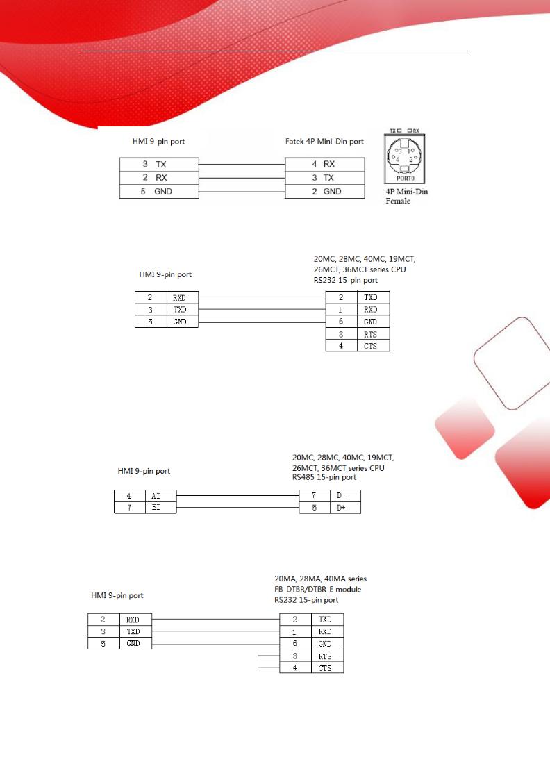
2.19.3 Cable making
(a) FBs Port0 RS232:
CPU port:
Fig1
(b) CPU RS485:
Fig2
(c)FB-DTBR/DTBR-E module RS232:
Fig3
71
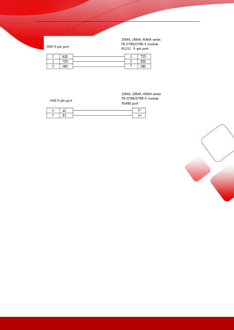
(d)FB-DTBR/DTBR-E module RS232:
Fig4
(e) FB-DTBR/DTBR-E module RS485:
Fig5
2.19.4 Device address
FATEK-FB series PLC
PLC address |
Range |
Data type |
Explanation |
M |
0~2001 |
Bit |
Internal auxiliary coil |
|
|
|
|
X |
0~255 |
Bit |
External input coil |
|
|
|
|
Y |
0~255 |
Bit |
External output coil |
|
|
|
|
S |
0~999 |
Bit |
Sequence control coil |
|
|
|
|
T |
0~255 |
Bit |
Timer |
|
|
|
|
C |
0~255 |
Bit |
Counter |
|
|
|
|
R |
0~9000 |
Word/Dword |
Register |
|
|
|
|
X |
0~255 |
Word/Dword |
Used as register |
|
|
|
|
Y |
0~255 |
Word/Dword |
Used as register |
|
|
|
|
M |
0~2001 |
Word/Dword |
Used as register |
|
|
|
|
S |
0~999 |
Word/Dword |
Used as register |
|
|
|
|
D |
0~3071 |
Word/Dword |
Used as register |
|
|
|
|
TD |
0~255 |
Word/Dword |
Used as register |
|
|
|
|
C16 |
0~199 |
Word/Dword |
16-bit counter |
|
|
|
|
C32 |
200~255 |
Word/Dword |
32-bit counter |
|
|
|
|
T |
0~255 |
Word/Dword |
Timer state |
|
|
|
|
72
2.20 Vigor VIGOR PLC
2.20.1 Device model
|
Series |
|
CPU |
|
Connected module |
|
Port |
|
Cable |
|
|
Device |
|
|
|
VB0-14M |
|
|
|
|
|
|
|
|
|
|
|
|
VB0-20M |
|
Direct connect to the CPU |
|
RS232 |
|
Fig 1 |
|
|
|
|
|
|
VB0-28M |
|
|
|
|
|
|
|
|
|
|
|
|
VB0-32M |
|
|
|
|
|
|
|
|
|
|
|
|
|
|
|
RS232 |
|
Fig 2 |
|
|
Vigor VB |
|
|
VB |
|
VB1-14MT-D |
|
|
|
|
|
|
|||
|
|
|
|
|
|
|
|
|
|
|||
|
|
|
|
|
|
|
|
|
|
Series |
||
|
|
|
VB1-24MT-D |
|
Connect to the extension |
|
|
|
|
|
|
|
|
|
|
|
|
RS422 |
|
Fig 3 |
|
|
PLC |
||
|
|
|
VB1-32MTMT-D |
card |
|
|
|
|
||||
|
|
|
|
|
|
|
|
|
||||
|
|
|
|
|
|
|
|
|
|
|||
|
|
|
VB2-16M |
|
|
|
|
|
|
|
|
|
|
|
|
|
|
|
RS485 |
|
Fig 4 |
|
|
|
|
|
|
|
VB2-32M |
|
|
|
|
|
|
|
||
|
|
|
|
|
|
|
|
|
|
|
|
|
|
|
|
|
|
|
|
|
|
|
|
|
|
|
VH |
|
VH -14MR |
|
Direct connect to the CPU |
|
RS232 |
|
Fig 1 |
|
|
|
|
|
|
|
|
|
|
|
|
|
|
|
|
2.20.2 Parameters
HMI:
Parameters |
Recommend |
Choices of settings |
Note |
|
settings |
|
|
PLC type |
Vigor VB series |
|
|
|
PLC |
|
|
|
|
|
|
Port |
RS232 |
RS232/RS485/RS422 |
|
|
|
|
|
Data bit |
7 |
7 or 8 |
|
|
|
|
|
Stop bit |
1 |
1 or 2 |
|
|
|
|
|
Parity |
Even parity |
Even/odd/no parity |
|
|
|
|
|
Baud rate |
19200 |
4800/38400/9600/115200/19200/187500 |
|
|
|
|
|
Station no. |
0 |
0~255 |
|
|
|
|
|
The default parameters of Vigor VB series PLC: 19200, 7, 1, even parity, station no.0
2.20.3 Cable making
73

(a) |
CPU |
RS232 |
USB-A: |
Fig1
(b) CPU direct connection or RS232 extenstion card:
Fig2
(c) CPU direct connection or RS485 extenstion card: 1 RS422 connection
Fig3
2 RS485 connection
Fi4
74

2.20.4 Device address
PLC address |
Range |
Data type |
Explanation |
X |
0~777 |
Bit |
External input coil |
|
|
|
|
Y |
0~777 |
Bit |
External output coil |
|
|
|
|
M |
0~9255 |
Bit |
Internal auxiliary coil |
|
|
|
|
S |
0~999 |
Bit |
Special auxiliary coil |
|
|
|
|
TSTATUS |
0~255 |
Bit |
Status of timer |
|
|
|
|
CSTATUS |
0~255 |
Bit |
Status of counter |
|
|
|
|
TCOIL |
0~255 |
Bit |
Timer coil |
|
|
|
|
CCOIL |
0~255 |
Bit |
Counter coil |
|
|
|
|
C16 |
0~199 |
Word |
16-bit counter |
|
|
|
|
C32 |
200~255 |
DWord |
32-bit counter |
|
|
|
|
D |
0~9255 |
Word/ |
Data register |
|
|
DWord |
|
|
|
|
|
TW |
0~255 |
Word/ |
Current timer value |
|
|
DWord |
|
|
|
|
|
X |
0~777 |
Word/ |
Used as register |
|
|
DWord |
|
|
|
|
|
Y |
0~777 |
Word/ |
Used as register |
|
|
DWord |
|
|
|
|
|
M |
0~9255 |
Word/ |
Used as register |
|
|
DWord |
|
|
|
|
|
S |
0~999 |
Word/ |
Used as register |
|
|
DWord |
|
|
|
|
|
75

2.21 Fuji SPB series PLC
2.21.1 Device model
Fuji MICREX-SX SPB series PLC
|
Series |
|
CPU |
|
Connected module |
|
Port |
|
Cable |
|
Device |
|
|
|
|
|
|
|
|
|
|
|
|
|
|
|
NW0P20 |
|
Communication adapter |
|
RS232 |
|
Fig 1 |
|
|
|
|
|
|
NW0LA-RS2 |
|
|
|
|
|
||
|
|
|
|
|
|
Fig 3 |
|
Fuji SPB |
|||
|
SPB |
|
NW0P30 |
|
|
|
|
|
|||
|
|
|
|
|
|
|
|
|
series PLC |
||
|
|
|
Communication adapter |
|
|
|
Fig 2 |
|
|||
|
|
|
NW0P40 |
|
|
RS485 |
|
|
|||
|
|
|
|
NW0LA-RS4 |
|
|
Fig 3 |
|
|
||
|
|
|
|
|
|
|
|
|
|
||
|
|
|
|
|
|
|
|
|
|
|
|
2.21.2 Parameters
HMI:
Parameter |
Recommend |
Choices of settings |
Note |
|
settings |
|
|
PLC type |
Fuji SPB series PLC |
|
|
|
|
|
|
Port |
RS232 |
RS232/RS485 |
|
|
|
|
|
Data bit |
8 |
7 / 8 |
|
|
|
|
|
Stop bit |
1 |
1 / 2 |
|
|
|
|
|
Parity |
Odd parity |
Even/odd/no parity |
|
|
|
|
|
Baud rate |
19200 |
4800/38400/9600/115200/19200/187500 |
|
|
|
|
|
Station no. |
0 |
0~255 |
|
|
|
|
|
2.21.3 Cable making
(a) NW0LA-RS2 module RS232:
Fig1
76

(b) NW0LA-RS4 module RS485:
Fig2
(c) RJ-45 RS422:
Fig3
2.21.4 Device address
PLC address |
Range |
Data type |
Explanation |
X |
0~15 |
Bit |
External input coil |
|
|
|
|
Y |
0~15 |
Bit |
External output coil |
|
|
|
|
M |
0~15 |
Bit |
Internal auxiliary coil |
|
|
|
|
L |
0~15 |
Bit |
Special auxiliary coil |
|
|
|
|
T |
0~511 |
Bit |
Timer |
|
|
|
|
C |
0~255 |
Bit |
Counter |
|
|
|
|
SM |
0~15 |
Bit |
Special auxiliary coil |
|
|
|
|
WX |
0~63 |
Word/DWor |
Used as register |
|
|
d |
|
|
|
|
|
WY |
0~63 |
Word/DWor |
Used as register |
|
|
d |
|
|
|
|
|
|
|
77 |
|

WM |
0~63 |
Word/DWor |
Used as register |
|
|
d |
|
|
|
|
|
WL |
0~255 |
Word/DWor |
Used as register |
|
|
d |
|
|
|
|
|
WSM |
32768~3302 |
Word/DWor |
Used as register |
|
3 |
d |
|
|
|
|
|
D |
0~8191 |
Word/DWor |
Data register |
|
|
d |
|
|
|
|
|
TW |
0~511 |
Word/DWor |
Used as register |
|
|
d |
|
|
|
|
|
CW |
0~255 |
Word/DWor |
Used as register |
|
|
d |
|
|
|
|
|
LD |
0~10000 |
Word/DWor |
Used as register |
|
|
d |
|
|
|
|
|
SD |
32768~3302 |
Word/DWor |
Used as register |
|
3 |
d |
|
|
|
|
|
78

2.22 Keyence KV series PLC
2.22.1Device model
|
CPU |
|
Connected module |
|
Port |
|
Cable |
|
Device |
|
KV-10DR |
|
|
|
|
|
|
|
|
|
KV-24 |
|
Direct connect to the CPU |
|
RS232 |
|
Fig 1 |
|
|
|
KV-16 |
|
|
|
|
|
|||
|
|
|
|
|
|
|
|
|
|
|
KV-40 |
|
|
|
|
|
|
|
|
|
|
|
|
|
|
|
|
|
Keyence KV series |
|
KZ-300 |
Serial port module KZ-L2 |
|
RS232 |
|
Fig 2, fig 3 |
|
||
|
|
|
|
|
|
|
|||
|
|
RS422 |
|
Fig 4 |
|
|
|||
|
|
|
|
|
|
|
|
||
|
|
|
|
|
|
|
|
|
|
|
|
|
|
|
RS232 |
Fig 5, fig 6 |
|
|
|
|
KV-700 |
Serial port module KZ-L20 |
|
|
|
|
|
|
|
|
|
RS422 |
|
Fig 7 |
|
|
|||
|
|
|
|
|
|
|
|
||
|
|
|
|
|
|
|
|
|
|
2.22.2 Parameters
HMI:
Parameters |
Recommend |
Choices of settings |
Note |
|
settings |
|
|
PLC type |
keyence KV series |
|
|
|
|
|
|
Port |
RS232 port |
RS232/RS422 |
|
|
|
|
|
Data bit |
8 |
7 or 8 |
|
|
|
|
|
Stop bit |
1 |
1 or 2 |
|
|
|
|
|
Parity |
Even parity |
Even/odd/no parity |
|
|
|
|
|
Baud rate |
9600 |
4800/38400/9600/115200/19200/187500 |
|
|
|
|
|
Station no. |
1 |
0~255 |
|
|
|
|
|
The default parameters of Keyence KV series PLC: 9600, 8, 1, even parity, station
no.1
2.22.3 Cable making
(a) CPU RS232 RJ-11:
79

1 2 3 4 5 |
6 |
Fig1
(b) Serial port module KZ-L2 Port1, RS232 connects to Keyence KZ-300 PLC:
Fig2
(c) Serial port module KZ-L2 Port2, RS232 connects to Keyence KZ-300 PLC:
Fig3
(d) Serial port module KZ-L2 Port2, RS422 connects to Keyence KZ-300 PLC:
Fig4
80

(e) Serial port module KV-L20 Port1, RS232 connects to Keyence KV-700 PLC:
Fig5
(f) Serial port module KV-L20 Port2, RS232 connects to Keyence KV-700 PLC:
Fig6
(g) Serial port module KV-L20 Port2, RS422 connects to Keyence KV-700 PLC:
Fig7
2.22.4 Device address
PLC address |
Range |
Data type |
Explanation |
R |
0~999 |
Bit |
Coil |
|
|
|
|
DM |
0~8000 |
word |
Data register |
|
|
|
|
81

2.23 Emerson EC20 series PLC
2.23.1Device model
|
Series |
|
CPU |
|
Connected module |
|
Port |
|
Cable |
|
Device |
|
|
|
|
|
COM0 port |
|
RS232 |
|
Fig 1 |
|
Emerson EC20 |
|
|
|
|
|
|
|
|
|
|
|
|
|
EC20 |
|
EC20 |
|
|
|
RS485 |
|
Fig 2 |
|
|
|
|
|
COM1 port |
|
|
|
Series PLC |
||||
|
|
|
|
|
|
|
|
|
|
||
|
|
|
|
|
|
RS232 |
|
Fig 3 |
|
||
|
|
|
|
|
|
|
|
|
|
||
|
|
|
|
|
|
|
|
|
|
|
|
2.23.2 Parameters
HMI:
Parameters |
recommend settings |
Choices of settings |
Note |
PLC type |
Emerson EC20 series PLC |
|
|
|
|
|
|
Port |
RS232 |
RS232/RS485 |
|
|
|
|
|
Data bit |
8 |
7 or 8 |
|
|
|
|
|
Stop bit |
1 |
1 or 2 |
|
|
|
|
|
Parity |
Even parity |
Even/odd/no parity |
|
|
|
|
|
Baud rate |
19200 |
4800/38400/9600/115200 |
|
|
|
/19200/187500 |
|
|
|
|
|
Station no. |
1 |
0~255 |
|
|
|
|
|
The default parameters of Emerson EC20 series PLC: 19200, 8, 1, even parity, station no.1
2.23.3 Cable making
(a) Emerson EC20 PLC COM0 (RS232):
Fig1
(b)Emerson EC20 PLC COM1 (RS232):
82
Fig2
(c) Emerson EC20 PLC COM1 (RS485):
Fig3
Note: Emerson EC20 PLC COM1 supports RS232 and RS485.
2.23.4 Device address
PLC address |
Range |
Data type |
Explanation |
X |
0~377 |
Bit |
External input coil |
|
|
|
|
Y |
0~377 |
Bit |
External output coil |
|
|
|
|
M |
0~2047 |
Bit |
Internal auxiliary coil |
|
|
|
|
S |
0~1023 |
Bit |
Special auxiliary coil |
|
|
|
|
T |
0~255 |
Bit |
Timer |
|
|
|
|
C |
0~255 |
Bit |
Counter |
|
|
|
|
SM |
0~9999 |
Bit |
Special internal auxiliary coil |
|
|
|
|
D |
0~7999 |
Word/DWor |
Data register |
|
|
d |
|
|
|
|
|
SD |
0~255 |
Word/DWor |
Used as register |
|
|
d |
|
|
|
|
|
Z |
0~15 |
Word/DWor |
Used as register |
|
|
d |
|
|
|
|
|
T |
0~255 |
Word/DWor |
Used as register |
|
|
d |
|
|
|
|
|
C16 |
0~199 |
Word/DWor |
16-bit counter |
|
|
d |
|
|
|
|
|
C32 |
200~255 |
Word/DWor |
32-bit counter |
|
|
|
|
|
|
83 |
|

d
2.24 OEMax NX7 series PLC
2.24.1 Device model
|
Series |
|
CPU |
|
Connected module |
|
Port |
|
Cable |
|
Device |
|
|
|
|
|
COM0 port |
|
RS232 |
|
Fig 1 |
|
|
|
|
|
|
|
|
|
|
|
|
|
|
|
NX7 |
|
NX7 |
|
|
RS232 |
|
Fig 2 |
|
OEMax NX7 |
|
|
|
|
|
|
|
|
|||||
|
|
|
|
|
|
|
|
|
Series PLC |
||
|
|
|
COM1 port |
|
RS485 |
|
Fig 3 |
|
|||
|
|
|
|
|
|
|
|
||||
|
|
|
|
|
|
|
|
|
|
|
|
|
|
|
|
|
|
RS232 |
|
Fig 4 |
|
|
|
|
|
|
|
|
|
|
|
|
|
||
|
|
|
|
|
|
|
|
|
|
|
|
2.24.2 Device address
HMI:
Parameter |
Recommend settings |
Choices of settings |
Note |
PLC type |
OEMax NX70 series PLC |
|
|
|
|
|
|
Port |
RS232 |
RS232/RS485 |
|
|
|
|
|
Data bit |
8 |
7 or 8 |
|
|
|
|
|
Stop bit |
1 |
1 or 2 |
|
|
|
|
|
Parity |
No parity |
Even/odd/no parity |
|
|
|
|
|
Baud rate |
9600 |
4800/38400/9600/115200 |
|
|
|
/19200/187500 |
|
|
|
|
|
Staion no. |
1 |
0~255 |
|
|
|
|
|
The default parameterso f OEMax NX7 PLC: 9600, 8, 1, no parity, station no.1
2.24.3 Cable making
(a) OEMax NX7 PLC COM1 (RS232):
Fig1
84

(b) OEMax NX7 PLC COM1 (RS485):
Fig2
(c) OEMax NX7 PLC COM2 RJ-45 (RS232):
8 7 6 5 4 321
Fig3
(d) OEMax NX7 PLC COM2 is RJ-45 8-pin port, short pin1 and 3 means RS485+; short pin2 and 4 means RS485- :
Fig4
OR
Fig5
85

2.24.4 Device address
PLC address |
Range |
Data type |
Explanation |
R |
R000.00~R31.15 |
Bit |
External I/O coil |
|
|
|
|
|
R32.00~R127.15 |
Bit |
Special coil |
|
|
|
|
L |
L000.00~L063.15 |
Bit |
Internal coil |
|
|
|
|
M |
M000.00~M127.15 |
Bit |
Internal auxiliary coil |
|
|
|
|
K |
K000.00~K127.15 |
Bit |
Internal holding coil |
|
|
|
|
F |
F000.00~F015.15 |
Bit |
Special coil |
|
|
|
|
TC |
TC0~TC255 |
Bit |
Timer /counter coil |
|
|
|
|
W |
0~6000 |
Word/DWord |
Data register |
|
|
|
|
R |
0~127 |
Word/DWord |
Used as register |
|
|
|
|
L |
0~63 |
Word/DWord |
Used as register |
|
|
|
|
M |
0~127 |
Word/DWord |
Used as register |
|
|
|
|
K |
0~127 |
Word/DWord |
Used as register |
|
|
|
|
F |
0~15 |
Word/DWord |
Used as register |
|
|
|
|
SV |
0~255 |
Word/DWord |
Timer/counter settings |
|
|
|
|
PV |
0~255 |
Word/DWord |
Timer/counter current value |
|
|
|
|
SR |
0~511 |
Word/DWord |
Special register |
|
|
|
|
86

2.25 Bosch Rexroth IndraControl L40 series PLC
2.25.1 Device model
Bosch Rexroth IndraControl L40 series PLC can communicate with Xinje HMI via COM0 and COM1.
CPU |
Connected module |
Port |
Cable |
Device |
|
|
|
|
Bosch Rexroth |
IndraControl L40 |
Direct connect to CPU |
RS232 |
Fig 1 |
IndraControlL40 |
|
|
|
|
Series PLC |
|
|
|
|
|
2.25.2 Parameters
HMI:
|
Parameters |
Recommend settings |
|
Choices of settings |
|
Note |
|
PLC type |
IndraControl L40 series PLC |
|
|
|
|
|
|
|
|
|
|
|
|
Port |
RS232 |
RS232 |
|
|
|
|
|
|
|
|
|
|
|
Data bit |
8 |
|
7 or 8 |
|
|
|
|
|
|
|
|
|
|
Stop bit |
1 |
|
1 or 2 |
|
|
|
|
|
|
|
|
|
|
Parity |
Even parity |
Even/odd/no parity |
|
|
|
|
|
|
|
|
|
|
|
Baud rate |
9600 |
|
4800/38400/9600/115200 |
|
|
|
|
/19200/187500 |
|
|
||
|
|
|
|
|
|
|
|
|
|
|
|
|
|
|
Station no. |
1 |
|
0~255 |
|
|
|
|
|
|
|
|
|
The default parameters of IndraControl L40 series PLC: 9600, 8, 1, even parity, station no.1
2.25.3 Cable making
IndraControl L40 PLC RS232:
Fig1
87

2.25.4 Device address
IndraControl L40 series PLC
PLC address |
Range |
Data type |
Explanation |
X |
0~9999 |
Bit |
External I/O coil |
|
|
|
|
B |
0~9999 |
Byte |
Used as register |
|
|
|
|
W |
0~9999 |
Word |
Used as register |
|
|
|
|
D |
0~9999 |
DWord |
Used as register |
|
|
|
|
R |
0~9999 |
DWord |
Used as register |
|
|
|
|
SB |
0~9999 |
Byte |
Used as register |
|
|
|
|
SW |
0~9999 |
Word |
Used as register |
|
|
|
|
SD |
0~9999 |
DWord |
Used as register |
|
|
|
|
88

2.26 OPTO 22 SNAP series PLC
2.26.1 Device model
|
Series |
|
CPU |
|
Connected module |
|
Port |
|
Cable |
|
Device |
|
OPTO 22 |
|
SNAP |
|
Direct connect to CPU |
|
RS232 |
Fig 1, fig 2 |
|
OPTO 22 series |
|
|
|
|
|
|
|
|
|
||||
|
|
|
|
RS485 |
|
Fig 3 |
|
||||
|
|
|
|
|
|
|
|
|
|
||
|
|
|
|
|
|
|
|
|
|
|
|
2.26.2 Parameters
HMI:
|
Parameters |
|
|
Recommend |
|
|
Choices of settings |
|
|
Note |
|
|
|
|
settings |
|
|
|
|
|
|||
|
|
|
|
|
|
|
|
|
|
|
|
|
PLC type |
|
OPTO 22 |
series |
|
|
|
|
|||
|
|
|
|
|
|
|
|
|
|
||
|
Port |
|
RS232 |
|
|
RS232/RS485 |
|
|
|
||
|
|
|
|
|
|
|
|
|
|||
|
Data bit |
8 |
|
|
7 or 8 |
|
|
|
|||
|
|
|
|
|
|
|
|
|
|||
|
Stop bit |
1 |
|
|
1 or 2 |
|
|
|
|||
|
|
|
|
|
|
|
|
|
|
||
|
Parity |
|
No parity |
|
|
Even/odd/no parity |
|
|
|
||
|
|
|
|
|
|
|
|
|
|||
|
Baud rate |
115200 |
|
4800/38400/9600/115200/19200/187500 |
|
|
|
|
|||
|
|
|
|
|
|
|
|
|
|||
|
Station no. |
1 |
|
0~255 |
|
|
|
|
|||
|
|
|
|
|
|
|
|
|
|
|
|
The default parameters of OPTO 22 series PLC: 115200, 8, 1, no parity, station no.1
2.26.3 Cable making
(a) RS232 connection:
Fig1
(b) RS485 connection:
89

Fig2
(c) RS232 connection:
Fig3
2.26.4 Device address
PLC address |
|
Range |
|
|
Data type |
Explanation |
DI |
0~9999 |
|
|
Bit |
External input coil |
|
|
|
|
|
|
|
|
DO |
0~9999 |
|
|
Bit |
External output coil |
|
|
|
|
|
|
|
|
PID000~PID03 |
0~6 |
|
|
Bit |
|
|
1 |
|
|
|
|
||
|
|
|
|
|
|
|
|
|
|
|
|
|
|
I |
0~9999 |
|
|
DWord |
Used as register |
|
|
|
|
|
|
|
|
F |
0~9999 |
|
|
DWord |
Used as register |
|
|
|
|
|
|
|
|
AI |
0~9999 |
|
|
DWord |
Used as register |
|
|
|
|
|
|
|
|
AO |
0~9999 |
|
|
DWord |
Used as register |
|
|
|
|
|
|
|
|
90

2.27 SAIA-Burgess PCD series PLC
2.27.1 Device model
SAIA—Burgess PCD series PLC communicates with Xinje HMI via socket A or socket B port.
(a) Direct connect to CPU
|
CPU |
|
Connected module |
Port |
Cable |
|
Device |
|
PCD1.M110 |
|
|
|
|
|
|
|
PCD1.M125 |
|
CPU PORT #0 |
RS232 |
Fig 1 |
|
|
|
PCD1.M135 |
|
|
|
|
|
|
|
|
|
|
|
|
|
SAIA—Burgess PCD |
|
PCD2.M120 |
|
|
|
|
|
|
|
|
|
|
|
|
|
|
|
PCD2.M150 |
|
CPU PORT #0 |
|
|
|
series |
|
|
|
|
|
|
||
|
PCD2.M170 |
|
|
RS485 |
Fig 2 |
|
|
|
|
|
|
|
|
|
|
|
|
|
|
|
|
|
|
|
PCD2.M480 |
|
CPU PORT #6 |
|
|
|
|
|
|
|
|
|
|
|
|
(b) Through serial port
|
CPU |
|
|
|
Connected |
|
Port |
|
Cable |
|
Device |
|
|
|
|
|
|
|
module |
|
|
|
|
|
|
|
PCD1.M125 |
|
|
|
|
RS485 |
|
Fig 4 |
|
|
||
|
PCD1.M135 |
|
|
|
|
|
|
|
||||
|
|
|
PCD7.F110 |
|
|
|
|
|
|
|||
|
PCD1.M110 |
|
|
|
|
|
|
|
|
|||
|
|
|
|
|
|
|
|
|
||||
|
|
|
|
|
|
|
|
|
|
|||
|
PCD1.M120 |
|
|
|
|
RS422 |
|
Fig 5 |
|
|
||
|
|
|
|
|
|
|
|
|
|
|||
|
PCD2.M480 |
|
|
|
|
|
|
|
|
|
||
|
|
|
|
|
|
|
|
|
|
|||
|
PCD2.M170 |
|
|
PCD7.F120 |
|
RS232 |
|
Fig 3 |
|
|
||
|
PCD2.M150 |
|
|
|
|
|
|
|||||
|
|
|
|
|
|
|
|
|
|
|||
|
Socket A |
|
|
|
|
|
|
|
|
|
||
|
|
|
|
|
|
|
|
|
|
|
|
|
|
|
|
Socket |
|
PCD2.F520 |
|
RS232 |
|
Fig 6 |
|
SAIA—Burgess |
|
|
|
|
|
|
|
|
|
|
||||
|
|
|
|
|
RS485 |
|
Fig 7 |
|
||||
|
|
|
|
|
|
|
|
|||||
|
|
|
B1 |
|
PCD7.F772/F802 |
|
|
|
PCD series |
|||
|
|
|
|
|
|
|
|
|
||||
|
|
|
|
|
RS422 |
|
Fig 10 |
|
||||
|
|
|
|
|
|
|
|
|||||
|
|
|
|
|
|
|
|
|
|
|
||
|
PCD2.M170 |
|
|
|
|
|
|
|
|
|
|
|
|
|
|
|
|
|
|
RS232 |
|
Fig 6 |
|
|
|
|
|
|
|
|
|
|
|
|
|
|
||
|
|
|
Socket |
|
PCD2.F520/F530 |
|
|
|
|
|
|
|
|
|
|
|
|
RS485 |
|
Fig 7 |
|
|
|||
|
|
|
B2 |
|
|
|
|
|
|
|||
|
|
|
|
|
|
|
|
|
|
|
||
|
|
|
|
|
|
PCD7.F772/F802 |
|
RS485 |
|
Fig 8 |
|
|
|
|
|
|
|
|
|
|
|
|
|
|
|
|
|
|
Socket |
|
|
|
RS232 |
|
Fig 9 or |
|
|
|
|
|
|
|
A |
|
|
|
|
fig 11 |
|
|
|
|
PCD2.M480 |
|
|
|
PCD2.F520/F522 |
|
|
|
|
|
||
|
|
|
|
|
|
|
|
|
|
|
||
|
|
Socket |
|
|
RS422 |
|
Fig 10 |
|
|
|||
|
|
|
|
|
|
|
|
|
||||
|
|
|
|
B |
|
|
|
|
|
|
||
|
|
|
|
|
|
|
|
|
|
|
|
|
|
|
|
|
|
|
|
|
|
|
|
|
|
91

2.27.2 Parameters
HMI:
|
Parameters |
|
Recommend |
Choices of settings |
Note |
|
PLC type |
|
SAIA—Burgess |
|
|
|
|
PCD |
|
|
|
|
|
|
|
|
|
|
|
|
|
|
|
|
Port |
|
RS232 |
RS232/RS485 |
|
|
|
|
|
|
|
|
Data bit |
8 |
7 or 8 |
|
|
|
|
|
|
|
|
|
Stop bit |
1 |
1 or 2 |
|
|
|
|
|
|
|
|
|
Parity |
|
No parity |
Even/odd/no parity |
|
|
|
|
|
|
|
|
Baud rate |
19200 |
4800/38400/9600/115200/19200/187500 |
|
|
|
|
|
|
|
|
|
Station no. |
0 |
0~255 |
|
|
|
|
|
|
|
|
SAIA—Burgess PCD series PLC: 19200, 8, 1, no parity, station no.0
2.27.3 Cable making
(a) Direct connect to PGU RS232:
Fig1
(b) Direct PGU RS485:
92
 Loading...