


BATTERY
CHECKER
Instruction Manual
SK-8535

CONTENTS
Thank you for purchasing "BATTERY CHECKER SK-8535". To obtain the maximum
performance of this instrument, read this Instruction Manual carefully, and take safe
measurement.
SAFETY PRECAUTIONS
・・・・・・・・・・・・・・・・・・・・・・・・・・・・・・・・・・・・・・・・・・・・・・・・・・・・・・・・・・・・・・・・・・・・・・
OPERATING PRECAUTIONS
・・・・・・・・・・・・・・・・・・・・・・・・・・・・・・・・・・・・・・・・・・・・・・・・・・・・・・・・・・・・・・・・・・・・
FEATURES
・・・・・・・・・・・・・・・・・・・・・・・・・・・・・・・・・・・・・・・・・・・・・・・・・・・・・・・・・・・・・・・・・・・・・・・・・・・・・・・・・・・・・・・・・・・・・・・・
UNPACKING AND INSPECTION
・・・・・・・・・・・・・・・・・・・・・・・・・・・・・・・・・・・・・・・・・・・・・・・・・・・・・・・・・・・・・・
NAME ILLUSTRATION
・・・・・・・・・・・・・・・・・・・・・・・・・・・・・・・・・・・・・・・・・・・・・・・・・・・・・・・・・・・・・・・・・・・・・・・・・
SPECIFICATIONS
1. General Specifications
・・・・・・・・・・・・・・・・・・・・・・・・・・・・・・・・・・・・・・・・・・・・・・・・・・・・・・・・・・・・・・・・・・・・・・・・・・・・・
2. Measurement Specifications
・・・・・・・・・・・・・・・・・・・・・・・・・・・・・・・・・・・・・・・・・・・・・・・・・・・・・・・・・・・・・・・・・・・・・
BEFORE USE
1. Technical Words
・・・・・・・・・・・・・・・・・・・・・・・・・・・・・・・・・・・・・・・・・・・・・・・・・・・・・・・・・・・・・・・・・・・・・・・・・・・・・・
2. Language / Date & Time Settings
・・・・・・・・・・・・・・・・・・・・・・・・・・・・・・・・・・・・・・・・・・・・・・・・・・・・・・・・・・・・・・
3. Others
・・・・・・・・・・・・・・・・・・・・・・・・・・・・・・・・・・・・・・・・・・・・・・・・・・・・・・・・・・・・・・・・・・・・・・・・・・・・・・・・・・・・・・・・・・・・・・・・・・
BATTERY TEST
・・・・・・・・・・・・・・・・・・・・・・・・・・・・・・・・・・・・・・・・・・・・・・・・・・・・・・・・・・・・・・・・・・・・・・・・・・・・・・・・・
CCA VALUE LIST
・・・・・・・・・・・・・・・・・・・・・・・・・・・・・・・・・・・・・・・・・・・・・・・・・・・・・・・・・・・・・・・・・・・・・・・・・・・・・・
GUIDES TO CHECK THE BATTERY CCA VALUES
・・・・・・・・・・・・・・・・・・・・・・・・・・・・・・・・
SYSTEM TEST
・・・・・・・・・・・・・・・・・・・・・・・・・・・・・・・・・・・・・・・・・・・・・・・・・・・・・・・・・・・・・・・・・・・・・・・・・・・・・・・・・・
PC CONNECTION
・・・・・・・・・・・・・・・・・・・・・・・・・・・・・・・・・・・・・・・・・・・・・・・・・・・・・・・・・・・・・・・・・・・・・・・・・・・・・
MENU
1. Print out
・・・・・・・・・・・・・・・・・・・・・・・・・・・・・・・・・・・・・・・・・・・・・・・・・・・・・・・・・・・・・・・・・・・・・・・・・・・・・・・・・・・・・・・・
2. Save the Test Result
・・・・・・・・・・・・・・・・・・・・・・・・・・・・・・・・・・・・・・・・・・・・・・・・・・・・・・・・・・・・・・・・・・・・・・・・・・
3. View the Saved Data
・・・・・・・・・・・・・・・・・・・・・・・・・・・・・・・・・・・・・・・・・・・・・・・・・・・・・・・・・・・・・・・・・・・・・・・・・・・・・・
4. Delete the Saved Data
・・・・・・・・・・・・・・・・・・・・・・・・・・・・・・・・・・・・・・・・・・・・・・・・・・・・・・・・・・・・・・・・・・・・・・・・・・・・
5. Date and Time Setting
・・・・・・・・・・・・・・・・・・・・・・・・・・・・・・・・・・・・・・・・・・・・・・・・・・・・・・・・・・・・・・・・・・・・・・・・・・・
6. Language Setting
・・・・・・・・・・・・・・・・・・・・・・・・・・・・・・・・・・・・・・・・・・・・・・・・・・・・・・・・・・・・・・・・・・・・・・・・・・・・・・・・・
7. Contrast Adjustment
・・・・・・・・・・・・・・・・・・・・・・・・・・・・・・・・・・・・・・・・・・・・・・・・・・・・・・・・・・・・・・・・・・・・・・・・・・・・・・
8. Temperature Setting
・・・・・・・・・・・・・・・・・・・・・・・・・・・・・・・・・・・・・・・・・・・・・・・・・・・・・・・・・・・・・・・・・・・・・・・・・・・・・・
MAINTENANCE
1. Changing the Printer Paper
・・・・・・・・・・・・・・・・・・・・・・・・・・・・・・・・・・・・・・・・・・・・・・・・・・・・・・・・・・・・・・
2. Formatting the Removable Disk
・・・・・・・・・・・・・・・・・・・・・・・・・・・・・・・・・・・・・・・・・・・・・・・・・・・・・・・・・・・・・・
3. DMP Folder
・・・・・・・・・・・・・・・・・・・・・・・・・・・・・・・・・・・・・・・・・・・・・・・・・・・・・・・・・・・・・・・・・・・・・・・・・・・・・・・・・・・・・・・・・
4. Periodical Check and Calibration
・・・・・・・・・・・・・・・・・・・・・・・・・・・・・・・・・・・・・・・・・・・・・・・・・・・・・・・・・・・・・
5. Software Version Update
・・・・・・・・・・・・・・・・・・・・・・・・・・・・・・・・・・・・・・・・・・・・・・・・・・・・・・・・・・・・・・・・・・・・・・・
6. Others
・・・・・・・・・・・・・・・・・・・・・・・・・・・・・・・・・・・・・・・・・・・・・・・・・・・・・・・・・・・・・・・・・・・・・・・・・・・・・・・・・・・・・・・・・・・・・・・・・
TROUBLE SHOOTING & REPAIR
・・・・・・・・・・・・・・・・・・・・・・・・・・・・・・・・・・・・・・・・・・・・・・・・・・・・・・・・・・・
WARRANTY
・・・・・・・・・・・・・・・・・・・・・・・・・・・・・・・・・・・・・・・・・・・・・・・・・・・・・・・・・・・・・・・・・・・・・・・・・・・・・・・・・・・・・・・・・・・・
1 - 3
4
5
6
7
-
8
9
9
10
-
11
11
11
12
-
19
20
-
21
22
23
-
26
27
-
29
30
-
32
33
-
34
35
36
37
38
38
39
40
-
41
42
43
43
43
43
44
45

1
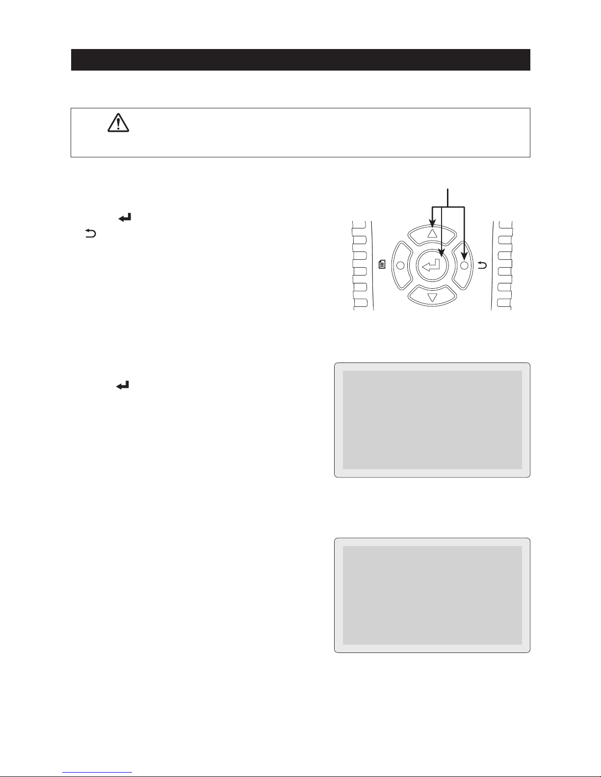
SAFETY PRECAUTIONS
(strict observance is required)
This instruction manual contains the important contents to prevent harm to
user or others and damage of property, and to use the instrument safely and
correctly.
Read this manual carefully and obey the contents after having understand the
following terms and symbols.
■Following symbols in this manual describe the harm and damage that
would be caused by incorrect ueage.
WARNING
CAUTION
■Caution marks that require your attention (equivalent marks have the same
meanings.)
This symbol in this manual advises the user of
an electrical shock hazard that could result in
serious injury or even death.
This symbol in this manual advises the user of
an electrical shock hazard that could cause
injury or material damages.
This symbol shows the warnings and cautions.
This symbol shows the prohibited matters.
This symbol shows the matters that is forced to do.

2
SAFETY PRECAUTIONS
(strict observance is required)
Do not place this instrument in any place where it will be subjected to
direct sunlight, high temperatures or the inside of the sun-heated vehicles.
Fire, electric shock or damage to the instrument may occur.
Make sure that the shift lever is set to "Parking" position (set to "Neutral" for
stick shift vehicle).
The vehicle runs accidentally and could cause unexpected accident,
electric shock, fire or damage to the instrument / vehicle.
Make sure that the parking brake is applied.
The vehicle runs accidentally and could cause unexpected accident,
electric shock, fire or damage to the instrument / vehicle.
Keep the instrument away from babies or children.
Important to prevent any accident, injury, or electric shock hazard.
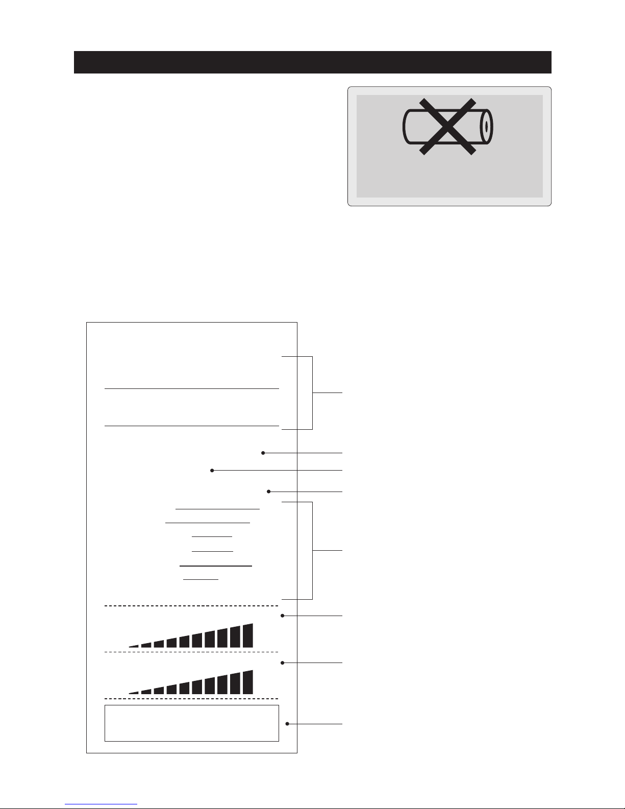
Take the measurement under well-ventilated environment.
The hydrogen gas which stayed around battery catches fire from the spark
that occurred when connecting the Battery Clips and might explode.
Do not drive the vehicle keeping the instrument connected.
Accident, electric shock, fire, or damage to the instrument / vehicle may occur.
Do not use this instrument with the hands or Battery Clips wetting.
Accident, electric shock, fire, or damage to the instrument / vehicle may occur.
Do not take the measurement for the battery which does not have enough battery fluid.
It causes combustion and the explosion of the battery.
Do not take the measurement around inflammables such as gasoline or oil.
Fire or explosion may occur.
Do not work in the dark place.
Accident, electric shock, fire, or damage to the instrument / vehicle may occur.
Do not get the instrument wet.
Fire or electric shock may occur.
Do not use the faulty instrument that can recognize such as display trouble,
switch failure.
Stop using the instrument immediately and consult with your local dealer.
Using the faulty instrument may cause the unexpected accident, fire, or
electric shock.
Do not touch the USB port with finger or insert the foreign objects in the USB port.
Accident, electric shock, fire, or damage to the instrument may occur.
Do not touch the heated part of the engine such as exhausting parts.
Important to prevent burn injury.
WARNING

3
SAFETY PRECAUTIONS
(strict observance is required)
WARNING
Do not use the instrument if it is in the abnormal condition.
Stop using the instrument immediately and consult with your local dealer
when recognizing smoke, strange smell, or abnormal noise.
Using the faulty instrument may cause the accident, fire, or electric shock.
Do not attempt to disassemble or modify the instrument.
Fire, electric shock, or damage to the instrument may occur.
Do not use the cables with which coating were damaged.
Fire or electric shock may occur.
Be careful about the instrument or the cables not to touch the heated part
of the engine such as exhausting parts.
Important to prevent any accident, or damage to the instrument / vehicle.
Be careful about the instrument or the cables not to be caught in the engine belt or cooling fan.
Short circuit or wire breaking may occur that could cause unexpected
accident, electric shock, or damage to the instrument / vehicle.
CAUTION
Be careful not to get the battery fluid into eyes or not to attach it to skin and clothes.
Loss of eyesight or injury may occur. If it gets into eyes, rinse immediately
and submit to medical treatment.
When testing the battery on vehicle, take the measurement after stopping
the engine and turning off the power supply of all in-vehicle apparatuses.
It causes injury or damage to the instrument.
Connect the Battery Clips to the battery with the correct polarity.
Reverse connection causes damage to the instrument.
Disconnect this instrument from battery soon after finishing the test.
It causes consumption of the battery and the ignition.
Do not use the other USB cable except the supplied one.
Damage to the instrument or PC may occur.
Do not hit, thrust and make scratch on the LCD display part.
It causes trouble or damage to the LCD.
Be careful not to jam the fingers in the Battery Clip.
It causes injury.
Be careful about your hands, gloves and clothes not to be caught in the engine
belt or cooling fan.
Important to prevent injury.

4
OPERATING PRECAUTIONS
Cautions for Handling
●Do not apply the engine oil to the metal part of the Battery Clips or USB Plug to prevent
contact failure.
●Do not apply engine oil, gasoline, antifreeze or battery fluid to the instrument to prevent
any damage on its surface.
●Do not polish the case with the fluid that contains alcohol to prevent the cracking.
●Use this instrument under the environment of -10℃ to 50℃, 80%RH or less to obtain
the accurate measurement. (Printer is operating at 0℃ to 50℃)
●Cables which coating are heat damaged might cause the short circuit. Do not use them
and replace into the new ones.
●Disconnect this instrument from battery soon after finishing the test to prevent trouble
of this instrument and running out of battery power.
●Do not touch the inside of the printer with finger to prevent trouble of this instrument.
●Do not put serious pressure on Printer Lever or Printer Cover to prevent trouble or
damage to this instrument.
●If Date and Time are not able to set, built-in battery for backup is exhausted. Ask
KAISE AUTHORIZED SERVICE AGENCY through your local dealer for repair service.
●Keep this instrument in supplied Carrying Case to avoid malfunction of the printer
trouble by dust penetration.
●Do not apply mechanical shock.
The shock such as dropping or beating might damage the instrument and may cause
the trouble.
●Do not pull cables forcibly.
Pulling the cables forcibly, such as when removing the Battery Clips from the battery
or USB Plugs from USB Port, may cause trouble such as the breaking of wire.
Cautions for Safekeeping
●Keep away the instrument from the following place.
・ Dusty area
・ The place where has the water splash
・ The place where applies the hard shock
・ -20℃ or less, 60℃ or more, 70%RH or more
・ The place where has the condensation
・ The place where is exposed to direct sunlight

5
FEATURES
■Portable instrument that can operate
with one hand.
■The software is upgradeable by
connecting supplied USB cable with
PC.(※)
■Capable of saving the test results up
to 359 data. Moreover, the test data
can edit on PC as text data by using
the supplied USB cable.
■Batteries for the vehicle equipped
with charge control system or idle
reduction system are testable.
■Test result can be printed on site by
built-in printer. English or Japanese
selectable.
■SK-8535 can test State of Charge
(SOC), State of Health (SOH), Start
Performance and Charging System
of the car battery.
※PC with Internet access is necessary.
File Edit View Favorite Tool Help
1631501B.TXT
Text Document
1KB
1631502B.TXT
Text Document
1KB
1631503B.TXT
Text Document
1KB
1631504B.TXT
Text Document
1KB
1631505B.TXT
Text Document
1KB
1631506B.TXT
Text Document
1KB
1631507B.TXT
Text Document
1KB
1631508B.TXT
Text Document
1KB
1631509B.TXT
Text Document
1KB
1631510B.TXT
Text Document
1KB
1631511B.TXT
Text Document
1KB
1631512B.TXT
Text Document
1KB
1631513B.TXT
Text Document
1KB
BAD
GOOD
CHARGE
MENU
[ バッテリーテスト ]
交換(バッテリー劣化)
JIS規格 95D31
565 CCA
MAX 32V
B
A
T
TERY
CHECKER
S
K
-
8
530
[ BATTERY TEST ]
Replace
JIS
95D31
BADGOOD CHARGE
MENU
MAX 32V
B
A
T
TERY
CHECKER
S
K
-
8
530
Linking to PC…
Serial Number
: 00001
Soft Ver : 3.00
■Auxiliary battery for hybrid car is
testable.
1631501B.TXT - Notepad
Battery Test Report
Date and Time
2016/03/15 15:00:00
-----------------------------Battery Test
(Aging test mode)
Test Result: Good
Battery Type: JIS
Battery Size: Q-85
Measured CCA: 615CCA
Battery Voltage: 12.780V
Battery Temperature: 24℃
Testing Mode
: Charge Controller / Idle Reduction
File Edit Format View Help
Test Result : Good
Date and T ime
2016/03/1515:00
(Aging Test Mode)
Battery Test Report
Periodical test is
SOC
(State of Charge)
: 100%
SOH
(State of Health)
: 100%
Battery Type
Model No.
Measured CCA
Battery Voltage
Temperature
Testing Mode
JIS
Q-85
615CCA
12.780V
24℃
Charge controller / Idle Reduction
Store Name
Person in Charge
System Test Report
Date and T ime
2016/03/1515:00
(12V System)
Test Result : Good
Test Result : Good
START PERFORMANCE TEST
CHARGING SYSTEM TEST
Cranking
Start Performance
8.619V
100%
Store Name
Person in Charge
B
A
T
TERY
CHECKER
SK-8535
CHARGE
BADGOOD
MAX 32V
MENU
CHARGE
BAD
GOOD
MENU
Choose the test
12.462 V
Battery Test
System Test
B
A
TTERY
CHECKER
SK-8535
CHARGE
BAD
GOOD
MAX 32V
MENU

6
UNPACKING AND INSPECTION
(Check before use)
Confirm if the following items are contained in the package in good condition.
If there are any damages or missing items, ask your local dealer for replacement.
①Battery Checker…1 pce.
③Printer Paper…2 rolls
(installed, and spare)
Available Printer Paper (10pcs per set)
Parts number:851
(Paper width:approx. 57mm,
length:approx. 5.8m)
②USB Cable (934)…1 pce.
⑤Instruction Manual…1 pce.
・Use above parts number when ordering.
※The following desiccant is enclosed
in the package for maintenance of
quality. Throw it away after opening
the package.
MENU
BATTERY
CHECKER
SK-8535
CHARGE BADGOOD
MAX 32V
④Carrying Case…1 pce.
SILICA
THROW A WA Y
"DO NOT EAT"
THROW A WA Y
"DO NOT EAT"
DESICCANT
GEL

MENU
BATTERY
CHECKER
SK-8535
CHARGE BADGOOD
MAX 32V
MENU
7
NAME ILLUSTRATION
Front Side
●
LED Indicators
①GOOD (Green LED):
L
ights up when battery test result is
"Good".
②CHARGE (Yellow LED):
Lights up when the battery is weak
and needs re-charging.
③BAD (Red LED):
lights up when battery test result is
"Replace" or needs replacement.
Flashes when battery test result is
"Attention" or "Weak Start Power".
●
USB Port
Plug the USB Cable into this port
when connecting to PC.
Connect to the battery.
Red to ○+, black to ○−.
● Battery Clips (Red・Black)
●
Printer
●
LCD
●
△ (UP SCROLL) Key
Scrolls up the display / use for
numerical settings.
Press this key to return to the
previous screen.
●
(BACK) Key
●
(ENTER) Key
Press this key to fix the settings.
●
(MENU) Key
Display the Menu screen.
MENU
●
▽ (DOWN SCROLL) Key
Scrolls down the display / use for
numerical settings.
CHARGE BADGOOD

8
NAME ILLUSTRATION
Rear Side
●
Serial Number
How to clip :
Open the battery clip widely and clip
it to the holder in the plastic part of
the clip. (Do not clip in the metal
part)
Clip Battery Clips here when not in
use.
●
Battery Clip Holder
●Do not clip in the metal part of the Battery clip. To prevent any
damages of the Battery Clip and Clip Holder.
CAUTION
00001
KAISE JAPAN4301-8530-1 1106
TO AVOID ELECTRICAL SHOCK, DO NOT CONNECT
BATTERY WITH WET HAND OR WET BATTERY CLIP.
感電事故防止のため、手やバッテリークリップ等が ぬれた状態
で 、バ ッテリーに接続しないでください。
SERIAL No.
WARNING
www.kaise.com

SPECIFICATIONS
Dot presentation, 128×64dots
English, Japanese (Default: English)
1 time/second
Green:Lights up when battery test result is "Good"
Yellow:Lights up when battery is weak and needs re-charging
Red:Lights up when battery test result is "Replace"
Flashes when battery test result is "Attention" or
"Weak Start Power"
Built-in
Approx.70cm (Clip and Bush are not included)
Testing battery or USB connection
DC8V to 32V (Testing battery), DC5V (USB Connection)
12V lead batteries ※For 24V battery, only Start-up
Performance Test or Charging System Test are possible.
JIS, DIN, EN, SAE, BCI, CCA and Industrial Rating
CCA:100 to 1400, Industrial Rating:1.0mΩ to 50.0mΩ
12V battery : Battery Test / Start Performance Test and Charging System Test
24V battery : Start Performance Test and Charging System Test
Accuracy at 23°C±5°C×0.01/°C
Test results can be saved to the internal memory up to 359 data.
※The data can be sent to PC via USB connection
From web site via USB connection
-10°C to 50°C, less than 80%RH (in non-condensing)
-20°
C
to 60°C, less than 70%RH (in non-condensing)
CE marking approved EN61326-1
248
mm
(H)×96mm(W)×50mm(D) ※
Cable and Bush are not included
Approx. 550g ※Printer paper is not included
1. General Specifications
2. Measurement Specifications
(23°C±5°C, <80%RH in non-condensing)
LCD
LANGUAGE
DISPLAY RATE OF
VOLTAGE MEASUREMENT
LED INDICATION
PRINTER
BATTERY CABLE LENGTH
POWER SUPPLY
TESTING VOLTAGE
TESTABLE BATTERIES
TESTABLE BATTERY STANDARDS
TESTABLE BATTERY PERFORMANCE
MEASURABLE TESTS
TEMPERATURE COEFFICIENT
FOR VOLTAGE MEASUREMENT
DATA SAVING
SOFTWARE UPDATE
OPERATING TEMPERATURE & HUMIDITY
STORAGE TEMPERATURE & HUMIDITY
SAFETY LEVEL
DIMENSION
WEIGHT
1.
2.
3.
4.
5.
6.
7.
8.
9.
10.
11.
12.
13.
14.
15.
16.
17.
18.
19.
20.
※Specification and appearance are subject to change without notice.
Range
16.000V
32.000V
Resolution
1mV
Maximum Input
Lower than 32V
Accuracy
(8V to 16V):± 0.15%±3dgt
(16V〜32V):± 0.15%±3dgt
Battery Voltage
※Overload indication:"Over voltage" is displayed.
Range
-20°C to 60°C
Resolution
1°C
Maximum Input
-20°C to 60°C
Accuracy
±3°C
Temperature
※
Accuracy is applied when measuring after leaving under constant temperature more than an hour.
9

10
BEFORE USE
●What is CCA?
CCA stands for Cold Cranking Amperes. It is defined as the current a battery at 0°F
(-18°C) can discharge for 30 seconds and maintain at least 7.2V (for JIS, SAE and BCI).
And it is defined as the current a battery at 0°F (-18°C) can discharge for 10 seconds
and maintain at least 7.5V (for EN and DIN). The battery which has the bigger CCA,
the higher ability to start an engine, CCA is one of the criterion for selection of the
battery.
●What is SOH (State of Health)?
SOH is the health condition of the battery, the state is expressed in percentage (%).
1. Technical Words
The current discharge at 0°F (-18°C) for 30 seconds
and maintain at least 7.2V.
The current discharge at 0°F (-18°C) for 10 seconds
and maintain at least 7.5V.
CCA definition of various standards
Standards CountriesCCA Definition
JIS
SAE
BCI
EN
DIN
Japan
USA
USA
EU
Germany
●What is SOC (StateofCharge)?
SOC is the charging condition of the battery, the state is expressed in percentage (%).
Definition of SOH in this product:
SK-8535 defines SOH 30% as the threshold of the battery replacement recommendation.
Test result shows "Replacement is necessary" when measured SOH is 30% or less and test
result of SOC is not "Charge/Retest".
※SOH(%) is calculated as the ratio of CCA standard value to CCA measured value.
※SOH(%) fluctuates due to the rate of deterioration and charging condition.
Definition of SOC in this product:
SK-8535 defines as SOC 100% when the battery voltage is higher than 12.756V. (Higher than
13.056V for the battery for industry)
※SK-8535 does not show the exact measurement voltage when testing the battery just after
an engine shutdown or just after charging. Test the battery after reducing the stimulated
condition according to the procedure mentioned in page 12.

11
BEFORE USE
2. Language / Date & Time Settings
●Set date and time before using this instrument. (Refer to "5. Date and Time Setting"
in page 37).
●Language changeable from English (default setting) to Japanese or simplified
Chinese. (Refer to "6. Language Setting" in page 38).
●What is Ripple Voltage?
Ripple Voltage is the feeble change of charging voltage which occurs when rectifying
the generated voltage by diode. If diode is damaged, the ripple voltage fluctuated
sharply and adversely affects battery and in-vehicle apparatus.
3. Others
●Protection film is put on the front plate of the
unit before shipment. Tear off the protection
film before using this instrument.
Tear off the protection film.
MENU
BATTERY
CHECKER
SK-8535
CHARGE BADGOOD
MAX 32V
●Initial display shows the factory default
settings.

12
BATTERY TEST
●This instrument forced to be restarted if the testing battery is extremely
exhausted and cannot afford to supply the workable current.
●
Test the battery in the state of the engine shutdown to obtain the accurate
measurement.
●
When testing 24V battery, test each 12V battery which is connected in series.
●
When testing the battery on vehicle, test the parked car after turning off the power
supply of all in-vehicle apparatuses which are using the electricity from battery
and locking the car door to obtain the accurate measurement.
●
Test result may change when testing the same battery repeatedly. Also, test result
may change when testing the weak battery after using the printer.
●
Test result may change, even when testing the same battery, depending on the
battery condition or change the storage environment.
●Test results may be higher than usual just after driving. When testing the battery
test of such a car, test it after doing the following procedure.
・Turn on the headlights for approx. 20 seconds.
・Turn off the headlights and test it more than 3 minutes after turning off the
headlights.
In case of the test result is "Charge/Retest" by turning on the headlights, shorten
the time of turning on the headlights after re-charging the battery, and lengthen
the time of intervals before testing.
When you do not perform the procedure mentioned above or testing battery unit
just after charging, test after an interval more than 2 hours.
●This instrument judges the battery condition with testing the basic use of the lead
battery such as charge-discharge characteristics. Test result is not for judging
whether the special control function can use for the vehicle or not.
●This instrument is for testing fundamental battery performance, charging and
discharging ability, but not for judging the capability of actuating the special
control function such as idle reduction system.
For the batteries working with such funcitons, charging ability may be weakened
in its using process. When the relevant functions cannot be activated, check the
system details in the maintenance manual of the vehicle.
●
The maximum CCA displayed with this unit is up to 1400CCA.
CAUTION

13
BATTERY TEST
Test the SOC (State of Charge) and SOH (State of Health) of the battery.
①Connect Black and Red battery clips to
minus ○− and plus ○+ battery terminals.
※Connect them to the nearest part of the
terminals is acceptable if the clips cannot
catch the battery terminals.
In this case, CCA may be measured lower
than the actual value.
Red
Black
Battery
●Make visual inspection for the battery to be tested before connecting battery clips
to the battery terminals.
●Replace the battery terminals if there is corrosion or crack occurs on the terminals.
●Connect the battery clips to the battery terminals tightly without loosening.
●Clean up the battery terminals and battery clips if there is greasy dirt.
●Do not test the battery which has any damages on its body or terminals. Replace
immediately.
●As for the battery which battery fluid almost decreases to LOWER line, refill the
purified water and make auxiliary charging.
●Replace the battery which battery fluid is discolored and decreases under the
LOWER line.
Test Preparation
MENU
BATTERY
CHECKER
SK-8535
CHARGE BADGOOD
MAX 32V
●Make sure to connect the battery clips tightly to battery terminals
to obtain the accurate measurement.
●Clean up the battery terminals and the battery clips before testing
to obtain the accurate measurement.
CAUTION
Choose the test
12.462 V
Battery Test
System Test
14
BATTERY TEST
Battery voltage
②The instrument turns on automatically and enters "Choose the test" screen (step ③)
after displaying the model number / software version number.
BATTERY CHECKER
SK-8535
Soft Version Number
Ver 3.00
Current version number
Battery Type?
12.462 V
JIS
DIN
③Select Battery Test, press (ENTER) Key.
※Display shows the connected battery voltage.
● (MENU) Key :
Move to MENU screen. (see page 35)
MENU
④Select the battery type to be tested. Select
the battery type, and press (ENTER) Key.
※Battery test does not work when the battery
voltage is higher than 13.6V. LCD shows
WARNING.
※When the battery voltage is higher than 16V,
LCD shows "OVER VOLTAGE" warning.
※When testing the batteries for industrial,
golf cart, leisure boat, or deep-cycle, select
"Input CCA" if the CCA is shown on the
battery. Oherwise, choose "Industry".

15
BATTERY TEST
Testing Mode ▲▼
Standard
Charge Controller/
Idle Reduction
Testing Mode ▲▼
Charge Controller/
Idle Reduction
Hybrid Auxiliary
Which Test Mode?
Aging Test
Unused Battery Test
⑥Select Test Mode.
Aging Test:for deterioration check.
Unused Battery Test:
for condition check of unused battery
⑤Select testing mode.
Select "Standard" for normal batteries.
Select "Charge Controller / Idle Reduction"
when testing following batteries ;
●
Charge control / idle reduction compatible
batteries
●
Batteries in Charge control / idle reduction
vehicles
※LCD shows "Industrial Rating" screen when
selecting "Industry" at ④ in page 14.
●When testing the auxiliary battery for
hybrid car, select "Hybrid Auxiliary" and
press (ENTER) Key.

16
BATTERY TEST
Input EN(DIN) Rating
1400 CCA
Test Start
※Selected battery standard is retained.
※If knowing only battery size like B24, D31, etc., select JIS of the greatest specifications
which is replaceable.
Input CCA rating
Select Model
Test Start
28B19
34B19
38B19
Select the Battery
A17
A19
B17
B19
⑦The following screen is displayed depending on the selected battery standards.
●"JIS"
Select the battery group from the list, and
press (ENTER) Key.
The list is classified by battery size or
functions such as idle reduction or hybrid
auxiliary.
Select battery number to be tested.
Press (ENTER) Key to start battery test.
Input the CCA rating using △(UP SCROLL) /
▽ (DOWN SCROLL) Keys.
Press (ENTER) Key to start battery test.
※Selected battery rating is retained.
●"EN(DIN)" / "SAE(BCI)" / "CCA input"

17
BATTERY TEST
※Input internal resistance (mΩ) value if it is available on the battery body or its
manual. If not, test the new (full-charged) battery selecting "NO" in the above step
to record the initial internal resistance. Input that value from the next testing.
※Battery condition (good / bad) cannot be tested without inputting internal
resistance (mΩ) value.
※Selected resistance value is retained.
Input mΩ
50.0 mΩ
Test Start
Input mΩ value
●Remove the all electric loads connected to the battery to be tested
to obtain the accurate measurement.
●
Battery test is effective for only 12V lead battery.
●
Generally, industrial battery is recommended to be replaced when
the internal resistance comes up to double of the unused battery.
Based on this, SK-8535 judges "Bad" when the test result becomes
double of the input industrial rating.
CAUTION
Industrial Rating?
YES
NO
(Test Start)
●"Industry"
Select "YES" if you can input the industrial
rating (internal resistance mΩ) and press
(ENTER) Key.
When choosing "NO", battery test starts.
※Battery condition (good / bad) is not tested
when choosing "NO".
(When selecting "YES")
Input mΩ value with using △(UP SCROLL) /
▽(DOWN SCROLL) Keys.
Press (ENTER) Key to start battery test.
18
BATTERY TEST
Green LED lights up when
test result is "Good"
[ BATTERY TEST ]
Good
JIS
55B24
・Battery voltage
・Testing method
・Testing Mode
・Comment
・CCA value (Standard mΩ for Industry)
・Measured CCA (measured mΩ for Industry)
・Temperature
・SOC (State of Charge)
※You can see following results on LCD.
・Battery test result
・Selected battery type
・Model (JIS only)
・SOH (State of Health)
⑧"Now testing..." is shown on LCD during
battery testing.
Now testing…
Battery Temperature
25 ℃
Test Start
●Input Battery Temperature
(when selecting manual temperature input in page 39, "8. Temperature Setting")
Input battery temperature in ℃ using △(UP
SCROLL) / ▽(DOWN SCROLL) Keys.
Press (ENTER) Key to start battery test.
※Input the temperatures of the battery fluid
or ○+terminal.
※Selected temperature value is retained.
⑨Read the test result on LCD.
Scroll the display with △(UP SCROLL) /
▽(DOWN SCROLL) Keys.
You can also check the results by LED.
・Green lights up when test result is "Good"
・Green & Yellow lights up when the battery
is fine but needs re-charging
・Yellow lights up when re-charging and
retest are needed.
・Red flashes when the test result is "Caution"
・Red lights up when battery replacement is
needed.
19
BATTERY TEST
※If the instrument displays right error message,
disconnect battery clips from the battery and
inspect following points.
●Do not pull Battery Clips forcibly when detaching from the battery.
It may damage the battery terminals.
CAUTION
Error
Restart the unit and
test again.
Check error point.
②Check for SK-8535
Make sure there are not any dirt or abnormality on the metal part of battery clips and
clip cables.
※Battery may be damaged if keeping getting errors in spite of checking above.
When the error message is kept displaying or measurement error is displayed even if
testing another battery, ask repair service to us, KAISE CORPORATION through your
local dealer.
Do you want to exit?
YES
NO
●Press (MENU) Key:Move to Menu screen (Print / Save Data / Delete Save Data)
in page 30.
※For the vehicle equipped with higher grade battery, start performance of engine may
have no problem even if the judgment result is "Replace". In this case, battery
replacement is recommended to prevent suddenly battery breakdown.
※The battery which is not charged for a long term may be judged "Replace" due to
decreasing CCA by self-discharge even if it is a new battery. Keep the battery with
periodical auxiliary charge to prevent deterioration by leaving with exhausted condition
for a long term.
MENU
⑩Press (ENTER) Key.
Select "Yes" to finish the test and return
to the battery type select screen (③ in
page 14).
①Check for the battery and vehicle
Make sure there are no dirt or abnormality
on the battery terminals and terminal cables.

20
CCA VALUE LIST (Battery Manufacturers and Their Models)
List to help you for checking the battery type either EN(DIN), SAE(BCI) or CCA Input
and their CCA values.
●Find the battery number (model name) and check its battery type and CCA.
●Input the CCA printed on the battery if it is different from the listed one.
This publication CCA value is subject to change without notice.
AC Delco
EN(DIN)
Model
20-55
20-55D
20-60
20-66
20-70
20-72
20-80
20-90
20-92
20-100
20-110
27-44
27-45H
27-50P
27-54H
27-55
27-60P
27-63H
27-66
27-70P
27-80
27-85
27-90
30-55
30-66
30-72
CCA EN(DIN)
630
525
500
500
650
700
780
850
600
800
1000
400
400
500
500
500
550
550
550
630
780
770
850
525
500
700
SAE(BCI)
Model
26-6MF
34-6MF
34-7MF
58-5MF
58-6MF
58R-6MF
65-6MF
65-7MF
75-6MF
75-7MF
78-6MF
78H-6MF
78-7MF
78DT-7MF
79-6MF
86-7MF
90-6MF
101-6MF
DCD26L
DCD26R
85BR60K
Voyager Marine
Model
M24MF
M27MF
M31MF
Deep cycle
Model
DC24
DC27
DC31
1111
11 5 0
11 5 1
31-901CT
759
CCA SAE(BCI)
550
535
700
430
560
585
650
850
650
735
675
675
770
850
880
690
600
690
500
500
610
CCA SAE(BCI)
400
550
625
CCA SAE(BCI)
500
580
660
750
625
625
900
950
BOSCH
PS-I Battery
Model
PSI-4C
PSI-6C
PSI-6H
PSI-7C
PSI-7G
PSI-7H
PSI-1A
High TEC AGM Battery
Model
HT-70-PN
HT-95-PN
Silver X
Model
SLX-5K
SLX-4E
SLX-4K
SLX-4L
SLX-6C
SLX-6H
SLX-7C
SLX-7F
SLX-7H
SLX-8B
SLX-8C
SLX-1A
SLX-1B
CCA EN(DIN)
360
480
600
680
640
680
760
CCA EN(DIN)
760
850
CCA EN(DIN)
550
460
300
300
650
610
790
730
730
810
810
910
850
Silver
Model
SL-4C
SL-4D
SL-4E
SL-4K
SL-4L
SL-4P
SL-5D
SL-6C
SL-6H
SL-7C
SL-7F
SL-7G
SL-7H
SL-8B
SL-8C
SL-1A
SL-1B
US Power Max
Model
UPM-78DT
UPM-75
UPM-65
UPM-58
UPM-58R
UPM-34
CCA EN(DIN)
360
360
420
300
300
420
420
480
600
680
680
640
680
760
720
760
850
CCA SAE(BCI)
830
650
750
600
600
610

21
CCA VALUE LIST (Battery Manufacturers and Their Models)
ATLAS
EN
Model
572-20
571-13
544-59
4DLT
543-17
554-57
562-19
568-18
580-43
585-15
600-38
BCI
Model
78DT-600
58-560
75-550
78-600
AGM
Model
AGM-RD26
AGM-YD26
CCA EN(DIN)
610
640
390
890
410
480
540
550
640
720
850
CCA SAE(BCI)
600
560
550
600
CCA SAE(BCI)
730
750
EXIDE
EA Series
Model
EA530
EA602
EA640
EA722
EA770
EA1000
Eco Power X
Model
EPX50
EPX55
EPX62
EPX65
EPX75
EPX80
EPX100
For American Cars
Model
EX78DT
EX75
EX65
EX58
EX58R
EX34
EX86
EX36R
EX31
Orbital Series
Model
ORB34XCD
ORB78DT
ORB75DT
Gel Battery
Model
G210
CCA EN(DIN)
540
600
640
720
760
900
CCA EN(DIN)
450
520
570
630
730
640
870
CCA SAE(BCI)
850
730
850
540
580
630
525
650
700
CCA SAE(BCI)
750
770
690
CCA SAE(BCI)
110 0
Moll(モル)
MOLL AGM
Model
81070
81095
m3 plus
Model
83046
83056
83058
83071
83075
83085
83091
83095
83110
Kamina
Model
07715
54459
54464
54577
54579
55565
55559
56219
56638
57024
57414
57539
60038
60032
595203076
61042
CCA EN(DIN)
760
850
CCA EN(DIN)
420
500
540
590
660
710
760
800
850
CCA EN(DIN)
360
360
360
300
300
420
420
480
510
540
680
640
850
680
760
800
OPTIMA
Red Top
Model
1050S
1050U
925S
925U
Yellow Top
Model
D1400S
D1000S
D1000U
YT-925SL
YT-925U
YT-B24
Blue Top
Model
D1400M
D1200M
D900M
SLI-4.2L
CCA SAE(BCI)
815
815
730
730
CCA SAE(BCI)
975
765
765
660
660
460
CCA SAE(BCI)
975
845
765
815
HEXA
Model
58-6MF
58R6MF
34-72
65-7MF
75-6MF
78-6MF
M24MF
M27MF
M31MF
CCA SAE(BCI)
585
585
535
650
650
675
550
570
625
ODYSSEY
Model
LB545
LB680
LB925
LB1200
LB1700
CCA SAE(BCI)
230
280
470
630
900
VARTA
Ultra Dynamic
Model
570901076
595901085
Silver Dynamic
Model
552401052
554400053
561400060
563400061
563401061
574402075
577400078
585200080
600402083
610402092
CCA SAE(BCI)
760
850
CCA EN(DIN)
520
530
600
610
610
750
780
800
830
920
GS YUASA
EU Series
Model
545-042
555-054
560-064
562-048
570-064
574-068
580-072
600-080
CCA EN(DIN)
420
540
640
480
640
680
720
800

22
GUIDES TO CHECK THE BATTERY CCA VALUES
●EN-standard Batteries
Check the model number shown as 9-digits numbers like "575121072".
Last 3 numbers mean 1/10 of its CCA value.
For example of the above number, CCA value should be "720 CCA" (072 x 10 = 720).
●DIN-standard Batteries
Check the model number shown as 5-digits numbers like "54459".
The second and third numbers mean 20Ah of the battery.
For example of the above number, it should be "44Ah".
Find the nearest Ah in the following table and input the "Standard-CCA" value.
●Others
For the batteries that do not have the above numbers, please check following points.
1) Check the last 3 numbers of the model number and try to input it as CCA value.
Example 1: 048 → 480 CCA / Example 2: 570 → 570 CCA
2) Check if 20Ah is printed on the battery surface. If printed, find the nearest Ah in
the following table and input the "Standard-CCA" value.
※Note : Be sure to check 20Ah not like 5Ah and others.
※Values in this table are the reference only. For more accurate testing, ask the
battery manufacturer for CCA value.
※Re-input the "Higher-CCA" value when the test result became higher than
the "Standard-CCA" value.
20Ah
35
40
45
50
55
60
65
70
75
80
85
90
100
110
Standard-CCA
300
320
340
380
450
500
560
620
680
720
740
800
810
820
Higher-CCA
360
390
420
420
540
620
700
720
750
780
800
850
850
1000
23
SYSTEM TEST
Test the Start Performance (check the engine starting ability) and Charging
System (checking generating condition of alternator.
BATTERY SYSTEM TEST
Turn off
the all electric
components.
③Turn off the all electric components and
press (ENTER) Key.
BATTERY SYSTEM TEST
12.462 V
12V System Test
24V System Test
②Select the battery to be tested either 12V
or 24V. Press (ENTER) Key.
Choose the test
12.462 V
Battery Test
System Test
Battery voltage
①Connect the instrument to the battery to be
tested (see ① to ② in pages 13 to 14).
Select System Test, press (ENTER) Key.
※Display shows the connected battery voltage.

24
SYSTEM TEST
⑥Charging System Test screen is displayed
as shown in right.
Press ENTER Key to fix the charging
voltage which is varied depending on the
generating condition of the alternator.
Then, the instrument displays system test
result as ⑦ in page 25.
④Start the engine when the instrument displays the following message.
⑤System test takes about 30 second maximum. Follow the message on the screen.
Now testing the
Battery System…
12V System
Now testing the
Battery System…
24V System
[ CHARGING SYSTEM TEST ]
Good
Charging 14.500 V
Key Test Result
Please start… an engine.

25
SYSTEM TEST
※You can see following results on LCD.
・Start performance test result
・Starting voltage (cranking battery voltage)
・Start performance (the ability that battery starts an engine)
・Charging system test result
・Charging voltage (battery voltage at the time of charging)
・Ripple voltage (ripple voltage of diode)
・Comment
Apply electric load.
Maximum power on
the air conditioner
and headlight.
Stop the test
if charging voltage
remains in low
level.
※The instrument displays the following message when the charging voltage is less
than 13V. When measuring the vehicle with charge control system, turn on some
electric components to apply electric load to the battery.
※For 24V system test, the message is shown when the charging voltage is less than 26V.
⑦Test Result screen as shown in the right is
displayed when finishing the system test.
You can scroll the screen with △ (UP
SCROLL) / ▽(DOWN SCROLL) Keys.
You can also check the results by LED.
・Green LED lights up when the all test
results are "Good".
・Red LED flashes when engine starter
system is weak.
・Red LED lights up when the whole
charging system including starter system
is weak.
[
START PERFORMANCE TEST
]
Good
Cranking 8.686 V
Start Performance
100 %
Green LED lights up when the
both of Battery System Test
Results are "Good"

26
SYSTEM TEST
●Press (MENU) Key:Move to Menu screen (Print / Save Data / Delete Save Data)
in page 30.
MENU
※Though the lowest operatable / testing voltage of this instrument is 8V DC, the testing
carries out normally even if the battery voltage drops lower than 8V DC during Start
Performance Test.
※Start Performance Test is not applicable to check the starter motor condition.
※The message "Start Performance 0%" means that the tested battery almost has no
power to start an engine. It does not mean the starting probability.
Do you want to exit?
YES
NO
⑧Press (ENTER) Key.
Select "Yes" to finish the test and back to
the test select screen (①in page 23).

27
PC CONNECTION
②The instrument turns on automatically when
connecting to active PC. Messages as shown
in the right are displayed.
※Internal memory is recognized as mass-
storage device (kaise SK-8535 USB Device)
when PC connection is completed.
※If your PC does not recognize the SK-8535,
try to use another USB port or to connect
through commercially available USB hub.
※It may take time to recognize the devise.
SK-8535 can connect to PC via privided USB cable. You can send test data to
PC in text format.
①Insert the provided USB cable to the USB port on the right side of the unit and
connect another side to PC.
●
Detach USB Cable after completing USB removing process from
PC to prevent unexpected trouble.
To USB Port
on PC
Pull up the
Rubber Lid
Linking to PC
・・・
Serial Number
: 00001
Soft Ver : 3.00
BADGOOD CHARGE
Current version number is displayed.
CAUTION

1631501B.TXT - Notepad
File Edit Format View Help
28
Battery Test Report
Date and Time
2016/03/15 15:00
-----------------------------(Aging Test Mode)
Test Result:Good
Battery Type:JIS
Battery Size:Q-85
Measured CCA:615CCA
Battery Voltage:12.780V
Battery Temperature:24℃
Testing Mode
:Charge Controller/Idle Reduction
SOC (State of Charge):10 0%
■■■■■■■■■■
SOH (State of Health):10 0%
■■■■■■■■■■
-----------------------------Comment
Periodical test is recommended.
------------------------------
PC CONNECTION
③Access to the memory of this instrument by PC operation to copy and paste the data to
the PC. Data format is "text" which is suitable for print out from PC.
(Example of PC display)
■Battery Test
Testing date and Time
Battery charging level (SOC)
Comments for test result
Battery aging level (SOH)
Battery test result
Condition of tested battery
Battery test mode

29
PC CONNECTION
※Test data are displayed in the language used for data saving.
④Detach USB Cable after completing "Safety Remove Hardware" process from PC.
■System Test
1631501S.TXT - Notepad
File Edit Format View Help
System Test Report
Date and Time
2016/03/15 15:00
-----------------------------(12V System)
Start Performance Test
TestResult:Good
Cranking:8.619V
Start Performance:10 0%
-----------------------------Charging System Test
Test Result:Good
Charging Voltage:14.523V
Ripple Voltage:0.110V
-----------------------------Comment
Periodical test is recommended.
------------------------------
Comments for test result
Engine start performance test result
Testing date and Time
12V / 24V System
Charging system test result
Battery condition at engine starting
Battery conditions

30
MENU
※When the thermal head is too much heated,
warning shown on LCD and printing stops.
Leave the unit for a while for cooling down.
②Select " YES" and press (ENTER) Key.
The instrument starts printing.
※If printing becomes dark by continuous
printing, stop printing for a while for
cooling down the printer thermal head.
Do you want to print?
YES
NO
High temperature,
printing quality declined.
Cool down the printer,
for some time.
①Press (MENU) Key in Battery Test result
(⑨ in page 18) or System Test result (⑦ in
page 25) screens to enter Menu screen.
Select " Print" and press (ENTER) Key.
2016/03/15 15:00
〈
MENU
〉
Print
Save Data
Delete Save Data
MENU
Now printing・・・
※The instrument displays right screen during
printing. After finishing, go back to test
result screen.
※Make sure to close printer cover to avoid
any printing error.
※When paper jam occurs, open the printer
cover and fix the paper.
※Unclear printing or unstable operation of this instrument may occur when using
weak battery for printing. In this case, save the test results in reference to "2. Save
the Test Result" in page 33, then print them out with good battery or PC in reference
to " PC Connection" in page 27.
1. Print Out
Print out the Battery Test and System Test results from built-in printer.
Test Result : Good
Date and Time
2016/03/1515:00
(Aging Test Mode)
Battery Test Report
Periodical test is
recommended.
SOC
(State of Charge)
: 100%
SOH
(State of Health)
: 100%
Battery Type
Model No.
Measured CCA
Battery Voltage
Temperature
Testing Mode
JIS
Q-85
615CCA
12.780V
24℃
Charge controller / Idle Reduction
Store Name
Person in Charge
31
MENU
※The instrument displays right screen when
printer paper is almost empty or unset. Set
new printer paper as per "1. Changing the
Printer Paper in page 40.
※This screen may not be displayed depending
on the sensor sensitivity.
Paper out・・・
Condition of tested battery
Printing Sample
※Saved data is printed out with a current setting language of this instrument.
(e.g.:The data saved in Japanese is printed in English if the present setting is "English".)
Store name and person in charge
Testing date and time
Battery aging level (SOH)
Battery charging level (SOC)
Battery test result
Battery test mode
Comment for test result
■Battery Test
System Test Report
Date and Time
2016/03/1515:00
(12V System)
Test Result : Good
Test Result : Good
Periodical test is
recommended.
START PERFORMANCE TEST
CHARGING SYSTEM TEST
Cranking
Start Performance
8.619V
100%
Charging Voltage
Ripple Voltage
14.523V
0.110V
Store Name
Person in Charge
32
MENU
Testing date and time
12V / 24V System
Battery conditions at engine starting
Battery conditions
Engine start performance test result
Charging system test result
Comment for test result
■System Test
Store name and person in charge
33
MENU
②Select " YES" and press (ENTER) Key to
save the test data.
2016/03/15 15:00
〈
MENU
〉
Print
Save Data
Delete Save Data
1631503B.TXT
Year (2016) B : Battery Test
S : System Test
Month (May)
Day (15th)
Number of savings on the same day
(Third time, in this case)
※Alphabet - digit code from 100 data
(Example) 100:A0, 101:A1…
110:B0, 111:B1…
359:Z9
※If more than 359 data are saved
in a day, return to "01".
①Press (MENU) Key in Battery Test result
(⑨ in page 18) or System Test result (⑦ in
page 25) screens enter Menu screen.
Select "Save Data" and press (ENTER)
Key.
2. Save the Test Result
Save the results of Battery Test and System Test up to 359 data.
※Each data is saved with following file name.
※Saved date and time reflect the date and time settings of this instrument. Make sure to
set them correctly in reference to "5. Date and Time Setting" in page 37.
■Example of file name (In case of the third time on the same day, May 15th, 2016)
9
A
B
C
:September
:October
:November
:December
1
2
8
:January
:February
:August
:
:
Do you want to save?
YES
NO
MENU

34
MENU
※Up to 359 data can be saved to the internal
memory. The instrument displays this
WARNING if the saved data exceeds 359.
Delete unnecessary data in reference to "4.
Delete the Saved Data" in page 36.
※The instrument displays this WARNING
when the memory capacity shortage.
Delete unnecessary data in reference to "4.
Delete the Saved Data" in page 36 to make
the storage capacity.
※The instrument displays this WARNING
when the same data already exists.
Delete the relevant in reference to "4. Delete
the Saved Data" in page 36.
※File name consists of the saving date.
Refer to "Example of file name" in page 33
for details.
※The instrument displays this message
when the system error occurs.
Stop test and format the removable disk in
reference to "2. Formatting the Removable
Disk" in page 42.
※All of the saved data are deleted after
formatting removable disk.
System Error
Can't save the data.
-WARNINGCan't save the data.
The number of saved
data exceed the limit.
-WARNINGCan't save the data.
Out of memory
capacity.
-WARNINGCan't save the data.
The same file name
existed.
②Select the data that you want to see, and
press (ENTER) Key.
※If there is no saved data, "No data found"
is displayed.
Data List
001/1631501B.TXT
002/1631502B.TXT
003/1631503B.TXT
004/1631504B.TXT
③Saved data are displayed as shown in the
right. Scroll the data by △ (UP SCROLL) /
▽ (DOWN SCROLL) Keys.
※Press (MENU) Key to print the viewing
data. See "1. Print Out" in page 30 for details.
※Saved data is displayed in a current setting
language of this instrument.
(e.g.:If English is set now, every data saved
in Japanese are displayed in English.)
2016/03/15 15:00
〈
MENU
〉
View Save Data
Delete Save Data
Date/Time Settings
35
MENU
Recall the saved data to see on the screen.
3. View the Saved Data
※The instrument displays this message
when the system error occurs.
Stop test and format the removable disk in
reference to "2. Formatting the Removable
Disk" in page 42.
※All of the saved data are deleted after
formatting removable disk.
[ BATTERY TEST ]
Good
JIS
55B24
System Error
Can't open the file.
MENU
①Press (MENU) Key in "Choose the Test"
screen (③ in page 14) to enter Menu screen.
Select "View Save Data" and press
(ENTER) Key.
MENU

③Select " YES" and press (ENTER) Key to
delete the test data.
②Select the data to delete from the data list,
and press (ENTER) Key.
※If there is no saved data, "No data found"
is displayed.
2016/03/15 15:00
〈
MENU
〉
View Save Data
Delete Save Data
Date/Time Settings
①Press (MENU) Key in "Choose the Test"
screen (③ in page 14) or test result screens
(⑨ in page 18 / ⑦ in page 25) to enter Menu
screen.
Select "Delete Save Data" and press
(ENTER) Key.
36
MENU
Saved data can be deleted in the following procedures.
4. Delete the Saved Data
Do you want to delete?
YES
NO
Data List
001/1631501B.TXT
002/1631502B.TXT
003/1631503B.TXT
004/1631504B.TXT
※When system error occurs, the message
as shown in the right is displayed. Stop
testing and format Removable Disk in
reference to "2. Formatting the Removable
Disk" in page 42.
※All saved data are deleted after formatting
removable disk.
System Error
Can't open the file.
MENU

2016/03/15 15:00
〈
MENU
〉
View Save Data
Delete Dave Data
Date/Time Settings
37
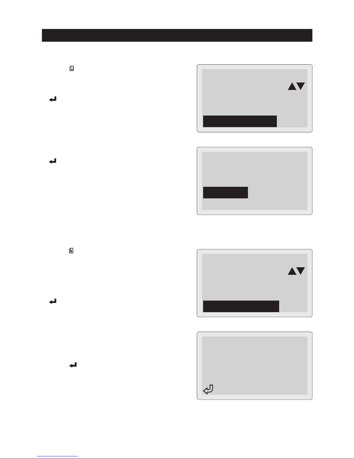
MENU
5. Date and Time Setting
②Date/Time Setting screen is displayed.
(Year (Y) is blinking)
Date/Time Settings
Y: 2016
MD: 03 / 15
HM: 15:00:00
Year blinks.
④Set Time (HM) until minute.
Press (ENTER) Key. Date/Time Settings
are fixed with resetting "Second" to 00 and
return to Menu Screen (previous Step ①).
③Set "Year" with using △(UP SCROLL) / ▽
(DOWN SCROLL) Keys and press
(ENTER) Key. Then "Month" starts to blink.
Set "Month" and press (ENTER) Key, Set
the "Day" in the same way.
Date/Time Settings
Y: 2017
MD: 09 / 15
HM: 15:00:00
The next setting blinks by
pressing (ENTER) Key.
Set until minute,
then press (ENTER) Key.
Date/Time Settings
Y: 2017
MD: 09 / 22
HM: 13:07:00
①Press (MENU) Key in "Choose the Test"
screen (③ in page 14) or test result screens
(⑨ in page 18 / ⑦ in page 25) to enter Menu
screen.
Select "Date/Time Settings" and press
(ENTER) Key.
MENU
38
6. Language Setting
Language Selection
日本語
ENGLISH
②Adjust LCD contrast in the range of 0 - 30
with △(UP SCROLL) / ▽(DOWN SCROLL)
Keys.
Press (ENTER) Key to fix the contrast
and return to Menu screen.
MENU
7. Contrast Adjustment
Contrast Control
▲
15
▼
Key OK
②Select preferred language and press
(ENTER) Key.
Language is fixed and return to Menu screen.
2016/03/15 15:00
〈
MENU
〉
Date/Time Settings
Select Language
Contrast Control
①Press (MENU) Key in "Choose the Test"
screen (③ in page 14) or test result screens
(⑨ in page 18 / ⑦ in page 25) to enter Menu
screen.
Select "Contrast Control" and press
(ENTER) Key.
2016/03/15 15:00
〈
MENU
〉
Delete Save Data
Date/Time Settings
Select Language
①Press (MENU) Key in "Choose the Test"
screen (③ in page 14).
Select "Select Language" and press
(ENTER) Key.
MENU
MENU

②Select "Manual" if you prefer to input the
battery temperature manually in Battery
Test (see page 18).
Press (ENTER) Key to return to Menu
screen.
※Default setting is "Auto".
Temperature Setting
Auto
Manual
2016/03/15 15:00
〈
MENU
〉
Select Language
Contrast Control
Temperature Setting
39
MENU
8. Temperature Setting
Set the battery tempearture input mode in Battey Test.
Default setting is "Auto". You can change it to "Manual" if necessary.
①Press (MENU) Key in "Choose the Test"
screen (③ in page 14) to enter Menu screen.
Select "Temperature Setting" and press
(ENTER) Key.
MENU

40
MAINTENANCE
1. Changing the Printer Paper
The instrument displays this screen when
the printer paper is running out or unset.
Set the new one in the following procedure.
Pull up the
Printer Lever
Put the inner side (printable
side) to downward.
③Prepare the new paper.
Peel off the fixing seal, and put it into the
printer compartment.
Be sure to put the inner side (printable
side) to downward as shown in the right.
①Pull up printer lever as shown in the right.
printer cover lifts up.
※Do not pull up / open the printer lever or
printer cover forcibly to avoid any damage
to the instrument.
●Do not pull up / open the ptinter lever or printer cover forcibly
to avoid any damage to the instrument.
●Be sure to put the printer paper facing the inner side (printable
side) to downward. Cannot print on the reverse side.
②Open the printer cover and remove old
printer paper.
Paper out・・・
GOOD
CHARGE
BAD
CAUTION
GOOD
CHARGE
BAD
④Pull the paper forward so that it extends
past the serrated edge of the paper slot.

41
MAINTENANCE
⑤Close the printer lever, then close the
printer cover with putting it over the pulled
out paper. Cut off the extra paper.
※Be sure to push the both ends of printer
cover when closing. Pushing center part
may damage the cover or the printer
module.
Close the
Printer Lever
first.
Close the printer cover pushing both
ends. (Do not push center part.)
●To avoid any trouble or damage to the printer module, be sure to close the
printer lever first when closing printer cover.
●Be sure to push the both ends of printer cover when closing. Pushing center
part may damage the cover or the printer module.
●To prevent discoloration, do not place the printer paper under in any place
where it will be subjected to direct sunlight or high temperatures / humidity.
●Keep this instrument in the supplied carrying case to avoid malfunction of the
printer trouble by dust penetration.
CAUTION
Gear wheel
●Be careful not to put the dust in the printer
compartment to prevent any malfunction
of the printer.
●Be sure not to reach the dust into the gear
wheel part to prevent printer trouble.
●Do not keep this instrument in the dusty
area to prevent printer trouble.
42
MAINTENANCE
MENU
Disk Formatting ?
YES - ENTER
NO - restart
2. Formatting the Removable Disk
①Connect the instrument to car battery (see
page 13) or PC (see page 27) holding
down (ENTER), △ (UP SCROLL), and
(BACK) Keys. The instrument turns on.
②The instrument displays this message.
Press (ENTER) Key to start formatting
the removable disk.
※Turn off the instrument to quit the formatting.
※The instrument also displays this screen
when the removable disk is fragmented.
Format the disk in the same way.
Hold down 3 keys.
Please restart
③The instrument displays this message after
formatting is done. Turn off the instrument.
●All of the saved data are deleted after formatting removable disk.
CAUTION
43
MAINTENANCE
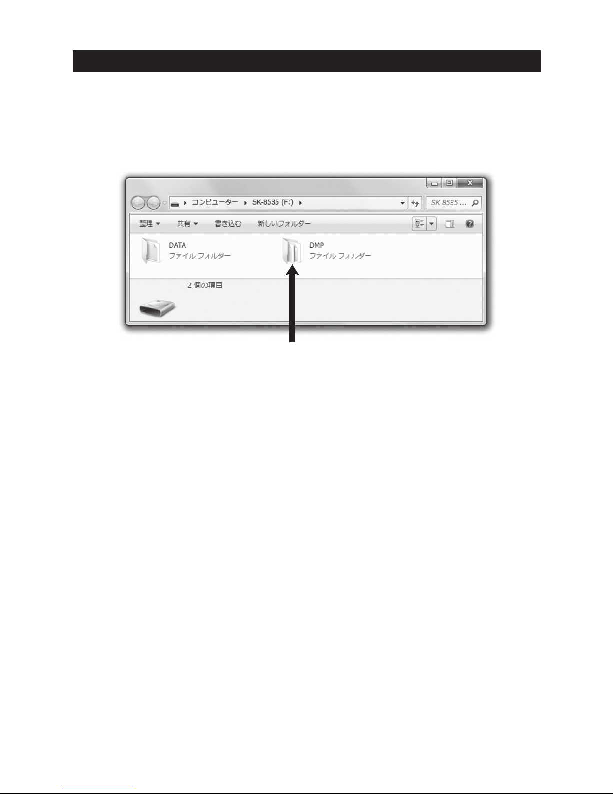
3. DMP Folder
DMPフォルダ
When measurement error occurs during the battery test process, the instrument
creates DMP folder in the removable disk to save the internal error data.
You do not need to delete this.
●You can update the internal software from our website
(http://www.kaise.com/NewEnglish.htm) when it is available. Download the file in
reference to the loading procedures.
5. Software Version Update
Periodical check and calibration is necessary to make safety measurements and to
maintain the specified accuracy. The recommended check and calibration term is
once a year and after the repair service. This service is available at KAISE
AUTHORIZED SERVICE AGENCY through your local dealer.
4. Periodical Check and Calibration
●If the metal part of the battery clip is soiled, wipe it off with soft cloth to obtain
the accurate measurement.
●If Date and Time are not able to set, internal backup battery is exhausted. Ask KAISE
AUTHORIZED SERVICE AGENCY through your local dealer for repair service.
6. Others

44
TROUBLE SHOOTING & REPAIR
If there are any failure with this instrument, check the following trouble shoots before
asking repair service. Ask KAISE CORPORATION AUTHORIZED SERVICE AGENCY
through your local dealer when there are any questions or troubles with this
instrument.
●Battery Clips are connected in the wrong polarity.
→ Connect Black clip to minus ○−,
and red clip to plus
○+
battery
terminals.
●Battery voltage goes down to 8V or lower.
→ Recharge the battery.
●Weak connecting of battery cable or USB cable.
→ Insert their plugs deeply.
●Metal parts of battery clips or battery terminals have
problems.
→Make them clean and check if there are not damaged.
Symptoms Possible Causes and Necessary Treatments
Cannot turn on
the instrument
●Backup battery (built-in) is exhausted.
→ Ask KAISE AUTHORIZED SERVICE AGENCY through
your local dealer for repair service.
Date / Time
are not saved
●System error is occurring.
→ Format the Removable Disk in reference to
"2. Formatting the Removable Disk" in page 42.
●Metal part of the battery clip or battery terminal is soiled.
→ Remove it cleanly.
●There in an abnormality in the battery.
→
Check visually the appearance of the battery; dirt of the
terminal, abnormality of the terminal cable, etc.
LCD displays
Measurement Error
Cannot save, view
and delete data
●Removable disk is fragmented.
→Format the disk in reference to "2. Formatting the
Removable Disk" in page 42.
Instrument freezes
with English letters
on LCD
●Printer paper is set in reverse.
→ Place the paper correctly in reference to "1. Changing
the Printer Paper"in page 40.
●Printer is jammed.
→ Open the printer cover and fix the paper jam.
Printer does
not work

45
WARRANTY
SK-8535 is warranted in its entirety against any defects of material or workmanship
under normal use and service within a period of one year from the date of purchase
of the original purchaser. Warranty service is available at KAISE AUTHORIZED
SERVICE AGENCY through your local dealer. Their obligation under this warranty is
limited to repairing or replacing SK-8535 returned intact or in warrantable defect with
proof of purchase and transport charges prepaid. KAISE AUTHORIZED DEALER and
the manufacturer, KAISE CORPORATION, shall not be liable for any consequential
damages, loss or otherwise. The foregoing warranty is exclusive and in lieu of all
other warranties including any warranty of merchantability, whether expressed or
implied.
This warranty shall not apply to any instrument or other article of equipment which
shall have been repaired or altered outside of KAISE AUTHORIZED SERVICE
AGENCY, nor which have been subject to misuse, negligence, accident, incorrect
repair by users, or any installation or use not in accordance with instructions
provided by the manufacturer.

KAISE AUTHORIZED DEALER
70-1201-8535-2 1606
422 Hayashinogo, Ueda City, Nagano Pref., 386-0156 Japan
TEL : +81-268-35-1601 / FAX : +81-268-35-1603
E-mail : sales@kaise.com
http://www.kaise.com
Product specifications and appearance are subject to change without notice due to continual improvements.
 Loading...