

Kaisai KOU-12HDN1, KOUB-24HDN1, KOUA-18HDN1-C0, KOUB-36HDN1-R, KOU-30HDN1 Service Manual
...
Service Manual
2010


MLCAC-UTSM-2010-10 Contents
Contents i
Part 1 General Information ................................................................................................. 1
Part 2 Indoor Units .............................................................................................................. 7
Part 3 Outdoor Units ......................................................................................................... 86
Part 4 Installation ............................................................................................................ 124
Part 5 Control................................................................................................................... 135
※The specifications, designs, and information in this book are subject to change without notice for
product improv e m ent.


MLCAC-UTSM-2010-10 General Information
General Information 1
Part 1
General Information
1. Model Names of Indoor/Outdoor Units .......................... 2
2. External A ppearance ....................................................... 3
2.1 Indoor Units ................................................................................. 3
2.2 Outdoor Units .............................................................................. 4
3. Nomenclature ................................................................... 5
4. Features ............................................................................ 6

Model Names of Indoor/Outdoor Units MLCAC-UTSM-2010-10
2 General Information
1. Model Names of Indoor/Outdoor Units
1.1 Indoor Units
R410A (capacity multiplied by 1000Btu/h)
Type
Function
12
18
24
30
36
48
60
New Four-way cassette
Cooling and heating
√ √
Four-way cassette
Cooling and heating
√ √ √ √ √ √
Duct
Cooling and heating
√ √ √ √ √ √ √
Ceiling & floor
Cooling and heating
√ √ √ √ √ √ √
Console
Cooling and heating
√ √
1.2 Outdoor Units
Model of outdoor unit and correspondin g indoor unit
Universal Outdoor unit Model
Compressor type
Compressor Brand
Matched indoor units
KOU-12HDN1 Rotary DC Inverter GMCC
KCA2-12HRDN1-Q
KTB-12HWDN1
KUB-12HRDN1
KFA-12HRDN1
KOUA-18HDN1-C0 Scroll DC Inverter Shenyang SANYO
KCA2-18HRDN1-Q
KTB-18HWDN1
KUB-18HRDN1
KCC-18HRDN1
KFA-18HRDN1
KOUB-24HDN1 Rotary DC Inverter HITACHI
KTB-24HWDN1
KUB-24HRDN1
KCC-24HRDN1
KOU-30HDN1 Rotary DC Inverter MITSUBISHI
KTB-30HWDN1
KUB-30HRDN1
KCC-30HRDN1
KOU-36HDN1 Rotary DC Inverter MITSUBISHI
KTB-36HWDN1
KUB-36HRDN1
KCC-36HRDN1
KOUB-36HDN1-R Rotary DC Inverter MITSUBISHI
KOU-48HDN1
Rotary DC Inverter
MITSUBISHI
KTB-48HWDN1
KUB-48HRDN1
KCC-48HRDN1
KOUB-48HDN1-R Rotary DC Inverter MITSUBISHI
KOUA-60HRDN1 Scroll DC Inverter MITSUBISHI
KTB-60HWDN1
KUB-60HRDN1
KOUD-60HDN1-R
Scroll DC Inverter
MITSUBISHI
KCC-60HRDN1

MLCAC-UTSM-2010-10 External Appearance
General Information 3
2. External Appearance
2.1 Indoor Units
Duct
Ceiling & Floor
Four-way Cassette
New Compact Four-way cassette
Console

External Appearance MLCAC-UTSM-2010-10
4 General Information
2.2 Outdoor Units
KOU-12HDN1
KOUA-18HDN1-C0
KOUB-24HDN1
KOU-30HDN1, KOUB-36HDN1-R
KOU-36HDN1, KOU-48HDN1, KOUB-48HDN1-R
KOUA-60HRDN1, KOUD-60HDN1-R

MLCAC-UTSM-2010-10 Nomenclature
General Information 5
3. Nomenclature
3.1 Indoor Unit
M U B - 18 H R D N1
Refrigerant Type
N1 R410A
DC Inverter
Control Mode
R Remote Control
Function Code
C cooling Only
H cooling & Heating
Capacity (¡ Á1000Btu/h)
Product Series
A First Time Design B Second Time Design
C Third Time Design
Product Category
C Cassette Type
T Duct Type
U Ceiling & Floor Type
H High Static Pressure Duct Type
Midea
3.2 Outdoor Unit
M O U D - 60 H D N1- R
Power Supply
R 380~415V, 3N, 50Hz
-- 220~240V, 1N, 50Hz
Refrigerant
N1 R410A
DC Inverter
Function Code
C cooling only H cooling & heating
Capacity (¡ Á1000Btu/h)
Product Series
A Time A Designed B Time B Designed
C Time C Designed D
Time D Designed
Universal Outdoor Unit
O Outdoor unit U Universal
Midea
F Console Type

Features MLCAC-UTSM-2010-10
6 General Information
4. Features
4.1 Universal outdoor unit design
Indoor unit with the same capacity can match with the same out door unit.
4.2 High efficiency and ener gy saving.
Thanks to the DC inverter technology and optimized piping system, the EER and COP of whole
series can easily reach A-class.
4.3 Low noise and low starting current.
Thanks to the DC inverter technology, the system can work with low noise, and very small starting
current.
4.4 Intelligent r ef r igerant adjustment technology.
Throttle part is made up of capillary and electronic expansion valve (EXV). The outdoor unit can
output the most accurate capacity in any condition.
4.5 Working in cooling mode under -15℃.
Outdoor unit built-in with low ambient kit, it can control the outdoor unit’s fan and cooling can be
performed throughout the year for computer rooms, banquet halls, etc. Wide operation range
covers outdoor temperatures as low as -15℃ for cooling.
4.6 Indoor & outd oor unit’s power supply is separate.
4.7 All indoor units have network control function.
4.8 All indoor units have Aut o-restart function.

MLCAC-UTSM-2010-10 Indoor Units
Indoor Units 7
Part 2
Indoor Uni ts
New Four-way Cassette Type (Compact) ........................... 8
Four-way Cassette Type .................................................... 18
Duct Type ............................................................................ 35
Ceiling & Floor Type .......................................................... 53
Console Type ..................................................................... 72

New Four-way Cassette Type (Compact) MLCAC-UTSM-2010-10
8 New Four-way Cassette Type (Compact)
New Four-way Cassette Type (Compact)
1. Features ............................................................................ 9
2. Specifications ................................................................ 10
3. Dimensions .................................................................... 11
4. Service Space ................................................................. 11
5. Wiring Diagrams ............................................................ 12
6. Air Velocity and Temperature Distributions ................. 13
7. Electric Characteristics ................................................. 14
8. Sound Levels ................................................................. 14
9. Accessor ies .................................................................... 15
10. The Specification of Pow er ......................................... 15
11. Field Wiring .................................................................. 16

MLCAC-UTSM-2010-10 Features
New Four-way Cassette (Compact) 9
1. Features
(1) Low operation noise
---Streamline plate ensures quietness
---Creates natural and comfortable environment
(2) Efficient cooling
---Equal, fast and wide—range c ool ing
(3) The adoption of the most advanced 3- Dimensional Screw fan
---Reduces the air resistance passing through
---Smoothes the air flow
---Makes air speed distribution t o t he heat exchange uniform
(4) Improvement for easy installation and maintenance
---Little space is required f or installation into a shallow ceiling
---Because of the compactness and weight reduction of the main unit and panel, all models can be
installed without a ho ist
(5) 360
0
Air Flow Panel
360
0
air outlet makes equal,fast ad wide range cooling
(6) Inside E-box design
The E-box is simply and safely build inside tge indoor unit, of witch ceiling side is 600mm*600mm. It is
convenient to install and maintain. Che cking the control part is easy, you only need to open the air return
grille.

Specifications MLCAC-UTSM-2010-10
10 New Four-way Cassette (Compact)
2. Specifications
Model
KCA2-12HRDN1-Q KCA2-18HRDN1-Q
Code 220042300070 220042400150
Power supply
V-ph-Hz
220~240-1-50
220~240-1-50
Cooling
Capacity Btu/h 13680-12000-4800 19260-18000-6120
Input W 1250-980-310
2070-1630-550
Current A 5.0
8.2
EER 3.26 3.25
Heating
Capacity Btu/h 15340-13000-4550 20800-20000-4800
Input W 1390-1090-370
2020-1600-560
Current A 5.8 8.2
COP
3.63
3.62
Indoor fan motor
Model YDK15-6P YDK37-4P
Qty 1 1
Input W 47.1/31.1/26.9 80/46/32
Capacitor uF 1.5 /450V 2 /400-450V
Speed(Hi/Mi/Lo) r/min 780/540/430 1000/710/570
Indoor coil
Number of rows 1 2
Tube pitch(a)×row pitch(b) mm 21×13.37 21×13.37
Fin spacing mm 1.3 1.3
Fin type (code) Hydrophilic aluminum Hydrophilic aluminum
Tube outside dia. and type mm φ7Inner grooved copper tube φ7Inner grooved copper tube
Coil length × height × width mm 1380×210×13.37 1370×210×26.74
Number of circuits 2 4
Indoor air flow (Hi/Mi/Lo) m3/h 683/530/510 800/710/560
Indoor noise level (sound pressure) dB(A) 42/41/38 42/41/38
Indoor unit
Dimension (W×H×D)(body) mm 570×260×570 570×260×570
Packing (W×H×D)(body) mm 655×290×655 655×290×655
Dimensi on (W×H×D)(panel) mm 647×50×647 647×50×647
Packing (W×H×D)(panel) mm 705×113×705 705×113×705
Net/Gross weight(body) kg 16/19 18/21
Net/Gross weight(panel) kg 3/5 3/5
Refrigerant type R410A R410A
Design pressure MPa 4.2/1.5 4.2/1.5
Refrigerant piping Liquid side/ Gas side mm φ6.4/φ12.7 φ6.4/φ12.7
Drainage water pipe diameter mm ODφ25 ODφ25
Controller R05/BGE (standard) R05/BGE (standard)
Operation temperature ℃ 17-30 17-30
Notes: 1. Nominal cooling capacities are based on the following conditions:
Indoor temp: 27°CDB, 19°CWB; Outdoor temp: 35°CDB; Equivalent ref. Piping: 7.5m(horizontal)
2. Nominal heating capacities are based on the following conditions:
Indoor temp: 20°CDB; Outdoor temp: 7°CDB, 6°CWB; Equivalent ref. Piping: 7.5m(horizontal)
3. Actual noise level may differ, depending on the room structure, etc, since these noise values are from an anechoic
room.

MLCAC-UTSM-2010-10 Dimensions
New Four-way Cassette (Compact) 11
3. Dimensions
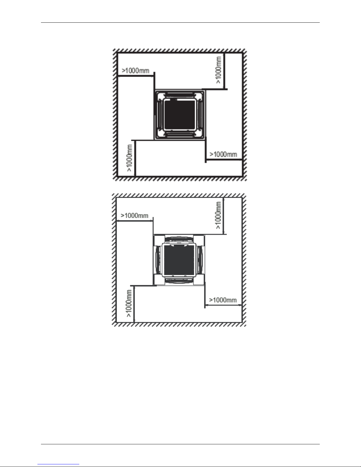
4. Service Space

Wiring Diagrams MLCAC-UTSM-2010-10
12 New Four-way Cassette (Compact)
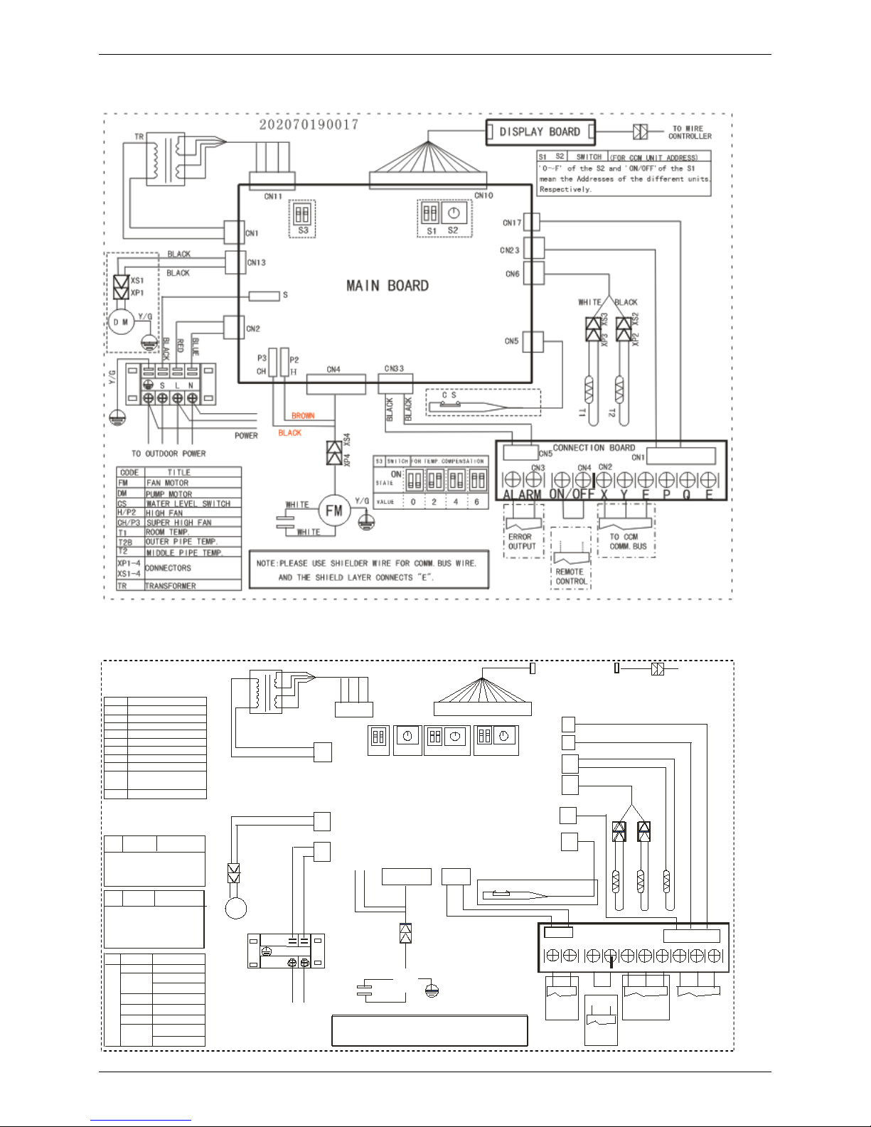
5. Wiring Diagrams
KCA2-12HRDN1-Q
KCA2-18HRDN1-Q

MLCAC-UTSM-2010-10 Air Velocity and Temperature Distrib ut i ons
New Four-way Cassette (Compact) 13
6. Air Velocity and Temperature Distributions
Airflow velocity
Temperature

Electric Characteristics MLCAC-UTSM-2010-10
14 New Four-way Cassette (Compact)
7. Electric Characteristics
Model
Indoor Units
Power
Supply
Hz MFA Min. Max. MFA
KCA2-12HRDN1-Q 50 220-240V 198V 254V 20
KCA2-18HRDN1-Q 50 220-240V 198V 254V 15
Remark:
MFA: Max. Fuse Amps. (A)
8. Sound Levels
1.0m
FOUR-WAY CASSETTE TYPE
Microphone
Model
Noise level dB(A)
H M L
KCA2-12HRDN1-Q 42 41 38
KCA2-18HRDN1-Q 42 41 38

MLCAC-UTSM-2010-10 Accessories
New Four-way Cassette (Compact) 15
9. Accessories
Name Shape Quantity
1. Drain joint (Be provided in outdoor unit.)
1
2. Remote controller
1
3. Remote controller holder
1
4. Mounting screw(ST2.9×10-C-H)
2
5. Alkaline dry batteries (AM4)
2
6. Owner's manual
1
7. Installation manual
1
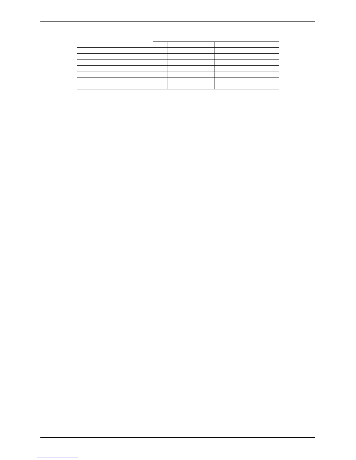
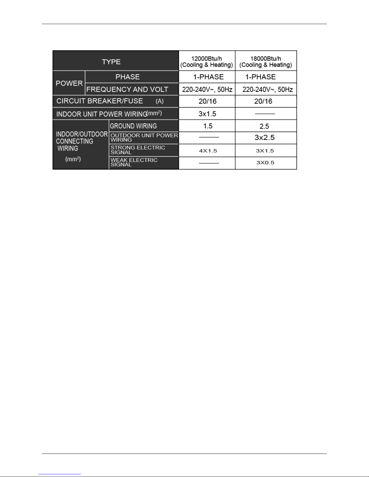
10. The Specification of Power

Field Wiring MLCAC-UTSM-2010-10
16 New Four-way Cassette (Compact)
11. Field Wiring
KCA2-12HRDN1-Q
KCA2-18HRDN1-Q

MLCAC-UTSM-2010-10 Field Wiring
New Four-way Cassette (Compact) 17
KCA2-12HRDN1-Q
KCA2-18HRDN1-Q

Four-way Cassette Type MLCAC-UTSM-2010-10
18 Four-way Cassette Type
Four-way Cassette Type
1. Features .......................................................................... 19
2. Specifications ................................................................ 22
3. Dimensions .................................................................... 25
4. Service Space ................................................................. 26
5. Wiring Diagrams ............................................................ 27
6. Air Velocity and Temperature Distributions ................. 28
7. Electric Characteristics ................................................. 29
8. Sound Levels ................................................................. 29
9. Accessories .................................................................... 30
10. The Specification of Pow er ......................................... 32
11. Field Wiring .................................................................. 33

MLCAC-UTSM-2010-10 Features
Four-way Cassette Type 19
1. Features
(1) Low operation noise
—Streamline plate ensures quietness
—Creates natural and com fortable environment
(2) Efficient cooling——Equal, fast and wide r ange cooling
(3) Excellent performance. The optimal evaporator & sufficient airflow volume guarantees the excellent
capacity
(4) The adoption of the most advanced 3- Dimensional Screw fan
—Reduces the air resistance passing through
—Smoothes the air flow
—Makes air speed distrib ution to the heat exchange uni form
(5) Fresh air makes life healthier and more comfortabl e.
(6) Drainage pump can take up t he condenser water to750mm.
(7) Ultra thin machine body to easy installation and maintenance. 18K~24K:230 mm, 36~48K:300mm.

Features MLCAC-UTSM-2010-10
20 Four-way Cassette Type
(8) Different color pa nels for choose: White、Gray、Blue、Black
(9) Swing angle of louver
1) Add one more swing motor, one motor driving two louvers. Controlling the interspace of each part,
minimizing the angle loss.
2) The swing angle of the first louver are 40~42 degrees and the second louver are 37~38 degrees.
New evaporator and inner conf iguration designed can acquire high heat-exchanger effect.
(10) More strengthening rib de sign around the panel, preventing the distortion for the p anel.
(11) New outlet frame design to make the phenomena of coagulation great improvement: prevent the
condensing water from dama ging the air guide strip.
(12) Adding rib on the panel of fan outlet, whic h can avoid the air outlet direct flow to people.
(13) 4 speeds available, opt i onal super high fan speed design suitable for the large bui lding over 3m high.
(14) Adding digital tube displaying on the display board. LED can display the Error Code to make the
malfunction checking eas i er.

MLCAC-UTSM-2010-10 Features
Four-way Cassette Type 21
(15) Reserve spaces for air side-outlet, it is available to connect duct pipe hence air supplying from the four
sides to nearby small room..
(16) The connecting pipe and drop h eight is h igher. Max. pipe length u p to 50m(refer to ①), and Max. drop
height up to 30m(refer to ②).
(17) Optimal design, small er Contr ol Box, Space saving and convenient for wiring,
Using fire resistance galvanized steel f or E-box material. Metal box make the control part more stable and
prevent damaging.
(18) 360°air flow panel : 360°air flow delivery ensures uni form airflow distribution. 60K is standard, the
others are optional.

Specifications MLCAC-UTSM-2010-10
22 Four-way Cassette Type
2. Specifications
Indoor Unit
Model
KCC-18HRDN1 KCC-24HRDN1 KCC-30HRDN1
Code
220042400370 220042500500 220042600010
Power supply
V-ph-Hz 220~240-1-50 220~240-1-50 220~240-1-50
Outdoor Unit
Model
KOUA-18HDN1-C0 KOUB-24HDN1 KOU-30HDN1
Code
220075200340
220075301070
220075401041
Power supply
V-ph-Hz 220~240-1-50 220~240-1-50 220~240-1-50
Cooling
Capacity Btu/h 19278-17981-5425 26784-23993-5425 35826-29998-8189
Input KW 1.51-1.47-0.56 2.8-2.18-0.98 4.5-2.71-1.1
current A 6.9-6.6-2.43
13.2-9.78-4.26
20.5-11.78-4.78
EER 3.25 3.32 3.24
Heating
Capacity Btu/h 20934-19994-4947 29002-26494-5800 40944-34000-9383
Input KW 1.50-1.43-0.72 2.60-2.10-1.05 3.37-2.74-1.3
current A 6.8-6.5-3.13 12.23-9.13-4.56 16.8-11.9-5.65
COP 3.68 3.69 3.64
Indoor fan
motor
Model
YDK60-6F YDK80-6E YDK90-6E
Qty
1 1 1
Input
W
85/75/70
120/100/90
143/116/100
Capacitor
μF
3uF/450V 3.5uF/450V 3.5uF/450V
Speed(Hi/Mi/Lo)
r/min
550/480/410 670/550/400 770/640/550
Indoor coil
Number of rows
2 2 2
Tube pitch(a)×row
pitch(b)
mm
21 x13.37 21 x13.37 21 x13.37
Fin spacing
mm
1.5 1.5 1.5
Fin type (code)
Hydrophilic
aluminum
Hydrophilic
aluminum
Hydrophilic
aluminum
Tube outside dia. and
type
mm
Ф7 Inner grooved
copper tube
Ф7 Inner grooved
copper tube
Ф7 Inner grooved
copper tube
Coil length × height ×
width
mm
1990x168x26.74 1990x168x26.74 1990x252x26.74
Number of circuits
8 8 12
Indoor air flow(Hi/Med/Lo)
m3/h
940/790/655 1327/1114/871 1545/1354/1187
Indoor noise level (Hi/Med/Lo)
dB(A)
40/39/37 42/41/39 44/42/41
Indoor unit
Dimension
(W×H×D)(body)
mm
840x230x840 840x230x840 840×300×840
Packing
(W×H×D)(body)
mm
900x250x900 900x250x900 900×320×900
Dimension
(W×H×D)(panel)
mm
950x55x950 950x55x950 950x55x950
Packing
(W×H×D)(panel)
mm
1035x90x1035 1035x90x1035 1035x90x1035
Net/Gross weight(body)
kg
24/30
25.5/28.5
30/36
Net/Gross
weight(panel)
kg
6/9 6/9 6/9
Refrigerant type
R410A R410A R410A
Design pressure
MPa
4.2/1.5 4.2/1.5 4.2/1.5
Refrigerant
piping
Liquid side/ Gas side
mm
φ6.4/φ12.7 φ9.5/φ15.9 φ9.5/φ15.9
Drainage water pipe diameter
mm
ODφ32 ODφ32 ODφ32
Controller
R05/BGE (standard) R05/BGE (standard) R05/BGE (standard)
Operation temperature
℃
17-30
17-30
17-30
Notes: 1. Nominal cooling capacities are based on the following conditions:
Indoor temp: 27°CDB, 19°CWB; Outdoor temp: 35°CDB; Equivalent ref. piping: 7.5m (horizontal)
2. Nominal heating capacities are based on the following conditions:
Indoor temp: 20°CDB; Outdoor temp: 7°CDB, 6°CWB; Equivalent ref. piping: 7.5m (horizontal)
3. Actual noise level may differ, depending on the room structure, etc, since these noise values are from an anechoic
room.

MLCAC-UTSM-2010-10 Specifications
Four-way Cassette Type 23
Indoor Unit
Model
KCC-36HRDN1 KCC-36HRDN1
Code
220042700390 220042700390
Power supply
V-ph-Hz 220~240-1-50 220~240-1-50
Outdoor Unit
Model
KOU-36HDN1 KOUB-36HDN1-R
Code
220075500651 220075500920
Power supply
V-ph-Hz 220~240-1-50 380-415-3-50
Cooling
Capacity Btu/h 42309-35826-9895 42309-35826-9895
Input
KW
5.0-3.25-2.3
5.0-3.25-2.3
current A 22.8-14.13-10 7.7-6.0-4.1
EER 3.23 3.23
Heating
Capacity Btu/h 45038-37617-12624 45038-37617-12624
Input
KW
3.94-3.03-2.0
3.94-3.03-2.0
current A 17.9-13.17-8.69 6.5-4.8-3.2
COP 3.63 3.63
Indoor fan motor
Model
YDK90-6E YDK90-6E
Qty
1 1
Input
W
143/116/100 143/116/100
Capacitor
μF
3.5uF/450V 3.5uF/450V
Speed(Hi/Mi/Lo)
r/min
770/640/550 770/640/550
Indoor coil
Number of rows
2
2
Tube pitch(a)×row pitch(b)
mm
21x13.37 21x13.37
Fin spacing
mm
1.5 1.5
Fin type (code)
Hydrophilic aluminum Hydrophilic aluminum
Tube outside dia. and type
mm
Ф7 Inner grooved copper tube Ф7 Inner grooved copper tube
Coil length × height × width
mm
1990x252x26.74 1990x252x26.74
Number of circuits
12 12
Indoor air flow(Hi/Med/Lo)
m3/h
1545/1354/1187
1545/1354/1187
Indoor noise level (Hi/Med/Lo)
dB(A)
44/42/41 44/42/41
Indoor unit
Dimension (W×H×D)(body)
mm
840×300×840 840×300×840
Packing (W×H×D)(body)
mm
900×320×900 900×320×900
Dimension
(W×H×D)(panel)
mm
950x55x950 950x55x950
Packing (W×H×D)(panel)
mm
1035x90x1035 1035x90x1035
Net/Gross weight(body)
kg
30/36 30/36
Net/Gross weight(panel)
kg
6/9 6/9
Refrigerant type
R410A R410A
Design pressure
MPa
4.2/1.5 4.2/1.5
Refrigerant piping
Liquid side/ Gas side
mm
φ9.5/φ15.9
φ9.5/φ15.9
Drainage water pipe diameter
mm
ODφ32 ODφ32
Controller
R05/BGE (standard) R05/BGE (standard)
Operation temperature ℃ 17-30 17-30
Notes: 1. Nominal cooling capacities are based on the following conditions:
Indoor temp: 27°CDB, 19°CWB; Outdoor temp: 35°CDB; Equivalent ref. piping: 7.5m (horizontal)
2. Nominal heating capacities are based on the following conditions:
Indoor temp: 20°CDB; Outdoor temp: 7°CDB, 6°CWB; Equivalent ref. piping: 7.5m (horizontal)
3. Actual no ise level may differ, depending on the room structure, etc, since these noise values are from an anechoic
room.

Specifications MLCAC-UTSM-2010-10
24 Four-way Cassette Type
Indoor Unit
Model
KCC-48HRDN1 KCC-48HRDN1 KCC-60HRDN1
Code
220042800480 220042800480 220042900010
Power supply
V-ph-Hz 220~240-1-50 220~240-1-50 220~240-1-50
Outdoor Unit
Model
KOU-48HDN1 KOUB-48HDN1-R KOUD-60HDN1-R
Code
220075700540 220075700690 220075801220
Power supply
V-ph-Hz 220~240-1-50 380-415-3-50 380-415-3-50
Cooling
Capacity Btu/h 51180-48000-11601 51180-48000-11601 56298-53568-14365
Input
KW
5.46-4.36-2.5
5.46-4.36-2.5
6.1-5.2-3.1
current A 25-18.96-10.8 9.0-6.9-4.0 9.8-7.43-4.43
EER 3.23
3.23
3.01
Heating
Capacity Btu/h 54592-52000-14330 54592-52000-14330 61416-60051-16377
Input
KW
5.6-4.16-2.3
5.6-4.16-2.3
6.1-4.91-2.7
current A 25.6-18.09-10 9.0-6.7-3.7 9.8-7.01-3.85
COP 3.66
3.66
3.56
Indoor fan
motor
Model
YDK90-6E YDK90-6E YDK90-6E-1
Qty
1 1 1
Input
W
143/116/100 143/116/100 143/116/100
Capacitor
μF
3.5uF/450V 3.5uF/450V 4uF/450V
Speed(Hi/Mi/Lo)
r/min
770/640/550 770/640/550 770/640/550
Indoor coil
Number of rows
2 2 3
Tube pitch(a)×row
pitch(b)
mm
21x13.37 21x13.37 21×13.37
Fin spacing
mm
1.5
1.5
1.5
Fin type (code)
Hydrophilic aluminum Hydrophilic aluminum Hydrophilic aluminum
Tub
e outside dia.
and type
mm
Ф7 Inner grooved
copper tube
Ф7 Inner grooved
copper tube
Ф7 Inner grooved copper
tube
Coil length × height
× width
mm
1990x252x26.74 1990x252x26.74 2080×252×40.11
Number of circuits
12 12 12
Indoor air flow(Hi/Med/Lo)
m3/h
1545/1354/1187 1545/1354/1187 1800/1480/1280
Indoor noise level (Hi/Med/Lo)
dB(A)
44/42/41 44/42/41 47/44/43
Indoor unit
Dimension
(W×H×D)(body)
mm
840×300×840 840×300×840 840×300×840
Packing
(W×H×D)(body)
mm
900×320×900 900×320×900 900×320×900
Dimension
(W×H×D)(panel)
mm
950x55x950 950x55x950 950x55x950
Packing
(W×H×D)(panel)
mm
1035x90x1035 1035x90x1035 1035x90x1035
Net/Gross
weight(body)
kg
30/36 30/36 35/39
Net/Gross
weight(panel)
kg
6/9 6/9 6/9
Refrigerant type
R410A R410A R410A
Design pressure
MPa
4.2/1.5 4.2/1.5 4.2/1.5
Refrigerant
piping
Liquid side/ Gas
side
mm
φ9.5/φ15.9 φ9.5/φ15.9 φ9.5/φ15.9
Drainage water pipe diameter
mm
ODφ32 ODφ32 ODφ32
Controller
R05/BGE (standard) R05/BGE (standard) R05/BGE (standard)
Operation temperature ℃ 17-30 17-30 17-30
Notes: 1. Nominal cooling capacities are based on the following conditions:
Indoor temp: 27°CDB, 19°CWB; Outdoor temp: 35°CDB; Equivalent ref. piping: 7.5m (horizontal)
2. Nominal heating capacities are based on the following conditions:
Indoor temp: 20°CDB; Outdoor temp: 7°CDB, 6°CWB; Equivalent ref. piping: 7.5m (horizontal)
3. Actual noise level may differ, depending on the room structure, etc, since these noise values are from an anechoic
room.

MLCAC-UTSM-2010-10 Dimensions
Four-way Cassette Type 25
3. Dimensions
Unit: mm
MODEL(Btu/h)
A B C
H
18000
230
Ф12.7
Ф6.4
>260
24000
230
Ф15.9
Ф9.5
>260
30000
300
Ф15.9
Ф9.5
>330
36000
300
Ф15.9
Ф9.5
>330
48000
300
Ф15.9
Ф9.5
>330
60000
300
Ф15.9
Ф9.5
>330
Service Space MLCAC-UTSM-2010-10
26 Four-way Cassette Type
4. Service Space
For 18-48k
For 60k

MLCAC-UTSM-2010-10 Wiring Diagrams
Four-way Cassette Type 27
5. Wiring Diagrams
KCC-18HRDN1、KCC-24HRDN1
KCC-30HRDN1、KCC-36HRDN1、KCC-48HRDN1、KCC-60HRDN1

Air Velocity and Temperature Distributions MLCAC-UTSM-2010-10
28 Four-way Cassette Type
6. Air Velocity and Temperature Distributi ons
Airflow velocity
Electronic
expansion valve
Oil separator
Compressor
Low pressure
switch
Oil return
Capillary
High pressure switch
Low pressure liquid
accumulator
Evaporator
Capillary
Outdoor unit
Indoor unit
4-way valve
Condenser
T5
Discharge temp. sensor
Filter
Filter
Condenser temp. sensor
T3
T4
Ambient temp. sensor
Filter
Filter
T2
Evaporator temp. sensor
Room temp. sensor
T1

MLCAC-UTSM-2010-10 Electric Characteristics
Four-way Cassette Type 29
7. Electric Characteristics
Model
Indoor Unit
Power
Supply
Hz
Voltage
Min
Max
MFA
KCC-18HRDN1
50
220-240
198
254
15
KCC-24HRDN1
50
220-240
198
254
15
KCC-30HRDN1
50
220-240
198
254
15
KCC-36HRDN1
50
220-240
198
254
15
KCC-48HRDN1
50
220-240
198
254
15
KCC-60HRDN1
50
220-240
198
254
15
KCC-60HRDN1
50
220-240
207
253
15
Remark:
MFA: Max. Fuse Amps. (A)
8. Sound Levels
Model
Noise level dB(A)
H M L
KCC-18HRDN1
40
39
37
KCC-24HRDN1
42
41
39
KCC-30HRDN1
44
42
41
KCC-36HRDN1
44
42
41
KCC-48HRDN1
44
42
41
KCC-60HRDN1
47
44
43

Accessories MLCAC-UTSM-2010-10
30 Four-way Cassette Type
9. Accessories
INSTALLATION FITTINGS
Name Shape Quantity
Installation paper board
1
Tubing & Fittings
Soundproof / insulation sheath
2
Connecting pipe group 1
Drainpipe Fittings
Out-let pipe sheath
1
Out-let pipe clasp
1
Drain joint
1
Seal ring
1
Remote controller & Its
Frame
Remote controller & Its Frame
1
Remote controller holder
1
Mounting screw(ST2.9×10-C-H)
2
Alkaline dry batteries (AM4)
2
Others
Owner's manual 1
Installation manual 1
Installation accessor y
(The product you have
might not be provided the
following accessories
Expansible hook
4
Installation hook
4
Orifice
1

MLCAC-UTSM-2010-10 Accessories
Four-way Cassette Type 31
MCC-60HRDN1
Installation Fittings
Name
Shape
Quantity
1. Expansible hook
4
2. Installation hook
4
3. Installation paper board
1
4. Bolt M6
4
Tubing & Fittings
5. Soundproof / insulation sheat h
2
Drainpipe Fittings
6. Out-let pipe
1
7. Out-let pipe sheath
1
8. Out-let pipe clasp
1
9. Tightening band
20
Remote controller & Its
Frame
10. Remote controller
1
11. Remote controller holder
1
12. Mounting screw(ST2.9
10-C-H)
2
13. Remote controller manual
1
14. Alkaline dry batteries (AM 4)
2
Others
15. Owner's manual
1
16. Installation manual
1
17. Net work winding
1
Optional fittings
18. Hook for four-way
air supply
panel
1

The Specification of Power MLCAC-UTSM-2010-10
32 Four-way Cassette Type
10. The Specification of Power

MLCAC-UTSM-2010-10 Field Wiring
Four-way Cassette Type 33
11. Field Wiring
Wiring chart

Field Wiring MLCAC-UTSM-2010-10
34 Four-way Cassette Type

MLCAC-UTSM-2010-10 Duct Ty pe
Duct Ty pe 35
Duct Type
1. Features .......................................................................... 36
2. Specifications ................................................................ 37
3. Dimensions .................................................................... 40
4. Service Space ................................................................. 41
5. Wiring Diagrams ............................................................ 42
6. Static Pressure ............................................................... 43
7. Electric Characteristics ................................................. 45
8. Sound Levels ................................................................. 46
9. Accessor ies .................................................................... 47
10. The Specification of Pow er ......................................... 48
11. Field Wiring .................................................................. 49

Features MLCAC-UTSM-2010-10
36 Duct Type
1. Features
● New structure design.
● Built-in drainage pump (Optical).
● Two air intake ways: from below or rear (standard).
● Wire controller is standard.
● Three speeds i ndoor unit.
● Fresh air inlet hole is reserv ed.

MLCAC-UTSM-2010-10 Specifications
Duct Ty pe 37
2. Specifications
Indoor Unit
Model
KTB-12HWDN1 KTB-18HWDN1 KTB-24HWDN1
Code
220070100130 220070200110 220070300130
Power supply
V-ph-Hz
220~240-1-50 220~240-1-50 220~240-1-50
Outdoor
Unit
Model
KOU-12HDN1 KOUA-18HDN1-C0 KOUB-24HDN1
Code
220075100071
220075200340
220075301070
Power supply
V-ph-Hz
220~240-1-50 220~240-1-50 220~240-1-50
Cooling
Capacity Btu/h
13102-12000-4777
21700-18000-7233
28524-24000-9519
Input KW
1.42-0.98-0.47
2.28-1.63-0.76
3.01-2.19-1.00
Rated current
A
6.5-4.9-2.2
10.4-7.4-3.5
13.7-10.0-4.6
EER
3.27
3.25
3.24
Heating
Capacity Btu/h
15490-13000-5152
24532-20000-8188
32891-26000-10952
Input KW
1.46-1.08-0.49
2.33-1.64-0.78
3.13-2.09-1.04
Rated current A
6.4-4.9-2.1
10.7-7.5-3.6
13.9-9.6-4.8
COP
3.7
3.66
3.64
Indoor fan
motor
Model
YSK25-4P YSK68-4P YSK74-4P
Qty 1 1 1
Input
W
107/65/52
107/65/52
163/93/75
Capacitor
μF 2μF /450V 3.5μF /450V 3.5μF /450V
Speed(Hi/Mi/Lo)
r/min 1150/800/700 1150/800/700 1000/750/680
Indoor coil
Number of rows
2 3 4
Tube pitch(a)×row
pitch(b)
mm 21×13.37 21×13.37 21×13.37
Fin spacing
mm 1.5 1.5 1.5
Fin type (code)
Hydrophilic
aluminum
Hydrophilic
aluminum
Hydrophilic
aluminum
Tube outside dia. and
type
mm
φ7 Inner grooved
copper tube
φ7 Inner grooved
copper tube
φ7 Inner grooved
copper tube
Coil length × height ×
width
mm 735×252×26.74 735×252×40.11 735×252×53.48
Number of circuits
3 4 6
Indoor air flow(Hi/Med/Lo)
m3/h 800/610/520 1170/770/650 1400/1100/1000
Indoor external static pressure (Hi)
Pa 40 70 70
Indoor noise level (Hi/Med/Lo)
dB(A) 37/30/26 44/36/33 45/43/41
Indoor unit
Dimension (W×H×D)
mm 920x210x635 920x210x635 920x270x635
Packing (W×H×D)
mm 1135x290x655 1135x290x655 1135x350x655
Net/Gross weight
kg 25/30 26/31 30/35
Refrigerant type
R410A R410A R410A
Design pressure
MPa 4.2/1.5 4.2/1.5 4.2/1.5
Refrigerant
piping
Liquid side/ Gas side mm φ6.4/φ12.7 φ6.4/φ12.7 φ9.5/φ15.9
Drainage water pipe diameter
mm ODφ25 ODφ25 ODφ25
Controller
KJR-10B/DP(T)-E KJR-10B/DP(T)-E KJR-10B/DP(T)-E
Operation temperature ℃ 17-30 17-30 17-30
Notes: 1. Nominal cooling capacities are based on the following conditions:
Indoor temp: 27°CDB, 19°CWB; Outdoor temp: 35°CDB; Equivalent ref. piping: 7.5m (horizontal)
2. Nominal heating capacities are based on the following conditions:
Indoor temp: 20°CDB; Outdoor temp: 7°CDB, 6°CWB; Equivalent ref. piping: 7.5m (horizontal)
3. Actual noise level may differ, depending on the room structure, etc, since these noise values are from an anechoic
room.

Specifications MLCAC-UTSM-2010-10
38 Duct Type
Indoor Unit
Model
KTB-30HWDN1 KTB-36HWDN1 KTB-36HWDN1
Code
220070400040 220070500750 220070500750
Power supply
V-ph-Hz
220~240-1-50 220~240-1-50 220~240-1-50
Outdoor
Unit
Model
KOU-30HDN1 KOU-36HDN1 KOUB-36HDN1-R
Code
220075401041 220075500651 220075500920
Power supply
V-ph-Hz
220~240-1-50 220~240-1-50 380~415-3-50
Cooling
Capacity Btu/h 36883-30000-12317 42104-36000-14057 42104-36000-14057
Input KW
3.98-2.79-1.33
4.39-3.25-1.45
4.39-3.25-1.45
Rated current A
18.3-12.8-6.1
19.7-14.6-6.7
7.0-5.2-2.3
EER 3.23 3.23 3.23
Heating
Capacity Btu/h
41490-32000-13818
51385-40000-17128
51385-40000-17128
Input KW
3.92-2.62-1.31
4.87-3.31-1.62
4.87-3.31-1.62
Rated current A
18.0-12.0-6.0
22.2-15.1-7.4
7.8-5.3-2.6
COP 3.63 3.63 3.63
Indoor fan
motor
Model
YSK100-4P YSK140-4P YSK140-4P
Qty 1 1 1
Input
W 227/142/115 291/168/138 291/168/138
Capacitor
μF 10μF /450V 10μF / 450V 10μF /450V
Speed(Hi/Mi/Lo)
r/min 935/700/620 1070/790/710 1070/790/710
Indoor coil
Number of rows
4 4 4
Tube pitch(a)×row
pitch(b)
mm 21×13.37 21×13.37 21×13.37
Fin spacing
mm 1.5 1.5 1.5
Fin type (code)
Hydrophilic
aluminum
Hydrophilic
aluminum
Hydrophilic
aluminum
Tube outside dia. and
type
mm
φ7 Inner grooved
copper tube
φ7 Inner grooved
copper tube
φ7 Inner grooved
copper tube
Coil length × height ×
width
mm 955×336×53.48 955×336×53.48 955×336×53.48
Number of circuits
8 8 8
Indoor air flow(Hi/Med/Lo)
m3/h 2250/1940/1720 2270/1890/1650 2270/1890/1650
Indoor external static pressure (Hi)
Pa 80 80 80
Indoor noise level (Hi/Med/Lo)
dB(A) 46/44/42 46/44/42 46/44/42
Indoor unit
Dimension (W×H×D)
mm 1140x270x775 1140x270x775 1140x270x775
Packing (W×H×D)
mm 1355x350x795 1355x350x795 1355x350x795
Net/Gross weight
kg 42/49 43/50 43/50
Refrigerant type
R410A R410A R410A
Design pressure
MPa
4.2/1.5
4.2/1.5
4.2/1.5
Refrigerant
piping
Liquid side/ Gas side mm φ9.5/φ15.9 φ9.5/φ15.9 φ9.5/φ15.9
Drainage water pipe diameter
mm ODφ25 ODφ25 ODφ25
Controller
KJR-10B/DP(T)-E KJR-10B/DP(T)-E KJR-10B/DP(T)-E
Operation temperature
℃
17-30 17-30 17-30
Notes: 1. Nominal cooling capacities are based on the following conditions:
Indoor temp: 27°CDB, 19°CWB; Outdoor temp: 35°CDB; Equivalent ref. piping: 7.5m (horizontal)
2. Nominal heating capacities are based on the following conditions:
Indoor temp: 20°CDB; Outdoor temp: 7°CDB, 6°CWB; Equivalent ref. piping: 7.5m (horizontal)
3. Actual noise level may differ, depending on the room structure, etc, since these noise values are from an anechoic
room.

MLCAC-UTSM-2010-10 Specifications
Duct Ty pe 39
Indoor Unit
Model
KTB-48HWDN1 KTB-48HWDN1 KTB-60HWDN1
Code
220070700100 220070700100 220070800170
Power supply
V-ph-Hz
220~240-1-50 220~240-1-50 220~240-1-50
Outdoor
Unit
Model
KOU-48HDN1 KOUB-48HDN1-R KOUA-60HDN1-R
Code
220075700341 220075700690 220075800161
Power supply
V-ph-Hz
220~240-1-50 380~415-3-50 380~415-3-50
Cooling
Capacity Btu/h 51658-48000-17230 51658-48000-17230 57731-54592-19243
Input KW 5.53-4.35-1.84 5.53-4.35-1.84 6.22-4.99-2.07
Rated current A 25.3-19.9-8.4 8.9-7.0-3.0 10.0-8.0-4.1
EER 3.22 3.22 3.21
Heating
Capacity Btu/h 59983-52000-19994 59983-52000-19994 68786-60000-22928
Input KW 5.71-4.16-1.90 5.71-4.16-1.90 6.59-4.85-2.20
Rated current A 25.0-19.0-8.7 9.2-6.7-3.1 10.6-7.8-3.5
COP 3.61 3.61 3.61
Indoor fan
motor
Model
YSK170-4P YSK170-4P YSK180-4P
Qty 1 1 1
Input
W 356/201/152 356/201/152 355/223/173
Capacitor
μF 10μF /450V 10μF /450V 10μF /450V
Speed(Hi/Mi/Lo)
r/min 1070/750/650 1070/750/650 1080/830/710
Indoor coil
Number of rows
4 4 4
Tube pitch(a)×row
pitch(b)
mm 21×13.37 21×13.37 21×13.37
Fin spacing
mm 1.5 1.5 1.5
Fin type (code)
Hydrophilic aluminum
Hydrophilic aluminum
Hydrophilic aluminum
Tube outside dia. and
type
mm
φ7 Inner grooved
copper tube
φ7 Inner grooved
copper tube
φ7 Inner grooved
copper tube
Coil length × height ×
width
mm 1030×378×53.48 955×336×53.48 1030×378×53.48
Number of circuits
8 8 8
Indoor air flow(Hi/Med/Lo)
m3/h 3010/2410/1940 3010/2410/1940 3150/2510/1990
Indoor external static pressure (Hi)
Pa 100 100 100
Indoor noise level (Hi/Med/Lo)
dB(A) 47/45/43 47/45/43 47/45/43
Indoor unit
Dimension (W×H×D)
mm 1200x300x865 1200x300x865 1200x300x865
Packing (W×H×D)
mm 1385x373x920 1385x373x920 1385x373x920
Net/Gross weight
kg
50/59
50/59
50/59
Refrigerant type
R410A R410A R410A
Design pressure
MPa 4.2/1.5 4.2/1.5 4.2/1.5
Refrigerant
piping
Liquid side/ Gas side mm φ9.5/φ15.9 φ9.5/φ15.9 φ9.5/φ15.9
Drainage water pipe diameter
mm ODφ25 ODφ25 ODφ25
Controller
KJR-10B/DP(T)-E KJR-10B/DP(T)-E KJR-10B/DP(T)-E
Operation temperature ℃ 17-30 17-30 17-30
Notes: 1. Nominal cooling capacities are based on the following conditions:
Indoor temp: 27°CDB, 19°CWB; Outdoor temp: 35°CDB; Equivalent ref. piping: 7.5m (horizontal);
2. Nominal heating capacities are based on the following conditions:
Indoor temp: 20°CDB; Outdoor temp: 7°CDB, 6°CWB; Equivalent ref. piping: 7.5m (horizontal)
3. Actual noise level may differ, depending on the room structure, etc, since these noise values are from an anechoic
room.

Dimensions MLCAC-UTSM-2010-10
40 Duct Type
3. Dimensions
Capacity
(KBtu)
Outline
dimension(mm)
Air outlet o
pening size
Air return
opening size
Size of outline dimension mou nted
plug
A B C D E F G H I J K L M
12/18 920 210 635 570 65 713 35 119 815 200 80 960 350
24 920 270 635 570 65 713 35 179 815 260 20 960 350
30/36 1140 270 775 710 65 933 35 179 1035 260 20 1180 490
48/60 1200 300 865 800 80 968 40 204 1094 288 45 1240 500

MLCAC-UTSM-2010-10 Service Space
Duct Ty pe 41
4. Service Space
Ensure enough space r equired for insta llat ion and maintenance.
All the indoor units reserve the hole to joint the fresh air pipe. The hole size as following:
Wiring Diagrams MLCAC-UTSM-2010-10
42 Duct Type
5. Wiring Diagrams
KTB-12HWDN1
KTB-18HWDN1 KTB1-24HWDN1 KTB-30HWDN1
KTB-36HWDN1 KTB-48HWDN1 KTB-60HWDN1
CN 1
C N13
CN2
CN 4
CN5
CN7
CN 6
CN1 7
CN 11
D M
BR OWN
FM
MAIN BOARD
W HITE
XS1
XP1
BLACK
ENC 2
IND OOR POWE R
P2
DISPLAY B OAR D
TR
CN1 0
RED
T2B
CON NECT ORS
XS 1-4
XP 1-4
T2
PU MP MOTOR
TRANSFOR MER
FM
CS
TR
DM
WAT ER L EVEL SWI TCH
C ODE
FAN MOTO R
T ITLE
T1
C S
T2B
T2
XP3
XS3
XS2
XP2
W HITE
BLAC K
R OOM TEMP .
T1
MIDDLE P IPE TEMP .
O UTER PIP E TE MP.
Y/G
N
L
NOT E:PL EASE USE SHIELDER WIRE FOR COMM.BUS WIRE,
202070390385
P3
BLAC K
CH
H
H /P2
CH /P3
HIG H FA N
SUPER HI GH F AN
9
8
7
5
140 00W
1 0500W
9 000W
7 100W
E NC1
4
5 600W
5 300W
CN9
TO OUTDOOR
COMM.BU S
TO CCM
CO MM.B US
S2
S1
S1
S2
CN 1
X Y
E P Q
EALARM
BLACK
BLACK
23CN
33CN
BLUE
E NC 2
S W1
EN C1
S3
160 00W
XP4
X S4
SW 1
WHITE
SWITCH
of the different units,
respectively.
(FOR INDOOR UNIT
ADDR ES S)
' 0~F ' o f the E NC 2 an d 'O N/O FF '
of the Sw1 mean the addresses
NUMBER
SWITCH
(FOR POWER)
PO WER
SWITCH
of the different ne t uni ts,
respectively.
(FOR CCM UNIT
ADDRESS)
'0~F' of the S2 and 'ON/OFF'
of the S1 mean the addre sses
FUNCTION OF SWITCH
ON/OFF
Y/G
REMO TE
CONT ROL
E RROR
O UTPU T
CN2
CN 4
CN 3
CN5
TO WIRE
CONTROLLER

MLCAC-UTSM-2010-10 Static Pressure
Duct Ty pe 43
6. Static Pressure
KTB-12HWDN1 KTB-18HWDN1
800
700
400300
Low speed
10
20
30
40
50
60
70
80
90
Pa
Air volume(m
/h)
3
External static pressure (Pa)
High speed
Mid speed
500
600
900
0
Super high speed
1200
Mid speed
High speed
External static pressure (Pa)
3
Air volume(m /h)
11001000900800700600
Pa
90
80
70
60
50
40
30
20
10
Low speed
200
300 400
500
Super high speed
KTB1-24HWDN1 KTB-30HWDN1
700
1500
1200
Mid speed
High speed
External static pressure (Pa)
3
Air volume(m /h)
11001000900800
Pa
90
80
70
60
50
40
30
20
10
Low speed
1300 1400
Super high speed
2000
1800
Mid speed
High speed
External static pressure (Pa)
3
Air volume(m /h)
1200
Pa
90
80
70
60
50
40
30
20
10
Low speed
1400 1600
2200
2400
Super high speed

Static Pressure MLCAC-UTSM-2010-10
44 Duct Type
KTB-36HWDN1 KTB-48HWDN1
2400
220016001400
Low speed
10
20
30
40
50
60
70
80
90
1100
Air vo lu me (m
/h)
3
External static pressure (Pa)
High speed
Mid speed
1200
1800
2000
Super high speed
Pa
3100
2800
19001600
Low speed
10
20
30
40
50
60
70
80
90
1000
Air volume(m
/h)
3
External static pre s sure (Pa)
High speed
Mid speed
1300
2200
2500
Pa
100
Super high speed
110
120
KTB-60HWDN1
2500
2200
1300
Mid speed
High speed
External static pressure (Pa)
3
Air volume(m /h)
1000
Pa
90
80
70
60
50
40
30
20
10
Low speed
1600 1900
2800
3100
100
3400
Super high speed
110
120

MLCAC-UTSM-2010-10 Electric Characteristics
Duct Ty pe 45
7. Electric Characteristics
Model
Indoor Unit
Power S upply
Hz Voltage Min. Max. MFA
KTB-12HWDN1 50 220-240 207 253 15
KTB-18HWDN1 50 220-240 207 253 15
KTB1-24HWDN1 50 220-240 207 253 15
KTB-30HWDN1 50 220-240 207 253 15
KTB-36HWDN1 50 220-240 207 253 15
KTB-48HWDN1 50 220-240 207 253 15
KTB-60HWDN1 50 220-240 207 253 15
Remark:
MFA: Max. Fuse Amps. (A)

Sound Levels MLCAC-UTSM-2010-10
46 Duct Type
8. Sound Levels
Suction
Discharge
Microphone
1.4m
Concealed Duct Type
DuctDuct
Model
Noise level dB(A)
H M L
KTB-12HWDN1 37 30 26
KTB-18HWDN1 44 36 33
KTB1-24HWDN1 45 43 41
KTB-30HWDN1 46 44 42
KTB-36HWDN1 46 44 42
KTB-48HWDN1 47 45 43
KTB-60HWDN1
47
45
43

MLCAC-UTSM-2010-10 Accessories
Duct Ty pe 47
9. Accessories
Tubing & Fittings
Name Shape Quantity
Soundproof / insulation sheath
2
Binding tape
1
Seal sponge
1
Drainpipe Fittings
(for cooling & heating)
Drain joint
1
Seal ring
1
Remote controller & Its Frame
Remote controller
1
Frame
1
Mounting screw(ST2.9 10-C-H)
2
Alkaline dry batteries (AM 4)
2
Remote controller manual
1
Wired controller & Its Frame
Wired controller
1
Others
Owner,s manual
1
Installation manual
1
EMS & It’s fitting
Magnetic ring (twist the electric wires L
and N around it to five circles)
1

The Specifi cat ion of Pow er MLCAC-UTSM-2010-10
48 Duct Type
10. The Specification of Power

MLCAC-UTSM-2010-10 Field Wiring
Duct Ty pe 49
11. Field Wiring

Field Wiring MLCAC-UTSM-2010-10
50 Duct Type
Air-conditioner link-circuit.

MLCAC-UTSM-2010-10 Field Wiring
Duct Ty pe 51

Field Wiring MLCAC-UTSM-2010-10
52 Duct Type

MLCAC-UTSM-2010-10 Ceiling & Floor Type
Ceiling & Floor Type 53
Ceiling & Floor Type
1. Features .......................................................................... 54
2. Specifications ................................................................ 55
3. Dimensions .................................................................... 58
4. Service Space ................................................................. 60
5. Wiring Diagrams ............................................................ 61
6. Air Velocity and Temperature Distributions ................. 63
7. Electric Characteristics ................................................. 65
8. Sound Levels ................................................................. 66
9. Accessor ies .................................................................... 67
10. The Specification of Pow er ......................................... 68
11. Field Wiring .................................................................. 69

Features MLCAC-UTSM-2010-10
54 Ceiling & Floor Type
1. Features
1.1. New design, more modern and elegant appearance.
1.2. Convenient installation
--The ceiling type can be easily installed into a
corner of the ceiling even if the c eiling is very narrow
--It is especially useful when installation of an air conditioner in the center of the ceiling is impossible
due to a structure such as one lighti ng.
1.3. Two direction auto swing (ver t i cal & horiz ontal) and wi de angle air flow,
--Air flow directional control minimizes the air resistance and produces wilder air flow to vertical
direction.
--The range of horizontal air discharge is widened which secures wider air flow distribution to provide
more comfortable air cir culation no matter where the unit is set up
1.4. Three level fan speed, more humanism de sign, meets different air-supply requirement.
1.5. Water proof by util i z i ng the absorbing plastic film on water collector
1.6. Easy operation. Auto-restart function, remote control and optional wire control method.
1.7. Low noise level plus compact size
--Shape of the blades has been im pr oved to prevent noise caused by turbulence.

MLCAC-UTSM-2010-10 Specifications
Ceiling & Floor Type 55
2. Specifications
Indoor Unit
Model
KUB-12HRDN1
KUB-18HRDN1
KUB-24HRDN1
Code
220044000060 220044100120 220044200240
Power supply
V-ph-Hz
220~240-1-50 220~240-1-50 220~240-1-50
Outdoor
Unit
Model
KOU-12HDN1 KOUA-18HDN1-C0
KOUB-24HDN1
Code
220075100071
220075200340
220075301070
Power supply
V-ph-Hz
220~240-1-50 220~240-1-50 220~240-1-50
Cooling
Capacity Btu/h
13648-12000-4777
19278-17981-5561
26955-23993-5561
Input KW
1.27-0.99-0.32
2.6-1.63-0.57 2.8-2.18-0.98
current
A
5.9-4.67-1.68
12.3-7.09-2.47
13.2-9.9-4.26
EER
3.24
3.24 3.22
Heating
Capacity Btu/h
16207-13000-4777
20984-19994-4947
29343-26494-5971
Input KW
1.38-1.07-0.36
2.34-1.59-0.72 2.60-2.12-1.05
current A
6.41-5.05-1.89
11.07-6.91-3.13 12.23-9.22-4.56
COP
3.73
3.69 3.66
Indoor fan
motor
Model
YSK25-6L YSK55-4L YSK55-4L
Qty
1 1 1
Input
W
33.4/31.1/29.5
125/105/85
125/105/85
Capacitor
μF
1.5uF/450V 2.5uF/450V 2.5uF/450V
Speed(Hi/Mi/Lo)
r/min
756/666/592 1310/1190/1040 1310/1190/1040
Indoor coil
Number of rows
3 3 3
Tube pitch(a)×row pitch(b)
mm
25.4×22
25.4 x 22
25.4 x 22
Fin spacing
mm
1.7 1.7 1.7
Fin type (code)
Hydrophilic
aluminium
Hydrophilic
aluminum
Hydrophilic
aluminum
Tube outside dia. and type
mm
Ф9.53 Inner grooved
copper tube
Ф9.53 Inner grooved
copper tube
Ф9.53 Inner grooved
copper tube
Coil length × height ×
width
mm
804x254x66 804x254x66 804x254x66
Number of circuits
3 3 3
Indoor air flow(Hi/Med/Lo)
m3/h
584/518/463 800/600/500 1000/900/700
Indoor noise level (Hi/Med/Lo)
dB(A)
40/37/33 43/41/38 45/43/40
Indoor unit
Dimension (W×H×D)
mm
990x203x660 990 x203 x660 990 x203 x660
Packing (W×H×D)
mm
1037x238x739 1037x238x739 1037x238x739
Net/Gross weight
kg
27/33 29/35 29/35
Refrigerant type
R410A R410A R410A
Design pressure
MPa
4.2/1.5 4.2/1.5 4.2/1.5
Refrigerant
piping
Liquid side/ Gas side
mm
φ6.4/φ12.7 φ6.4/φ12.7 φ9.5/φ15.9
Drainage water pipe diameter
mm
ODφ25 ODφ25 ODφ25
Controller
R05/BGE (standard) R05/BGE (standard) R05/BGE (standard)
Operation temperature
℃
17-30 17-30 17-30
Notes: 1. Nominal cooling capacities are based on the following conditions:
Indoor temp: 27°CDB, 19°CWB; Outdoor temp: 35°CDB; Equivalent ref. Piping: 7.5m(horizontal)
2. Nominal heating capacities are based on the following conditions:
Indoor temp: 20°CDB; Outdoor temp: 7°CDB, 6°CWB; Equivalent ref. Piping: 7.5m(horizontal)
3. Actual noise level may differ, depending on the room structure, etc, since these noise values are from an anechoic
room.

Specifications MLCAC-UTSM-2010-10
56 Ceiling & Floor Type
Indoor Unit
Model
KUB-30HRDN1 KUB-36HRDN1 KUB-36HRDN1
Code
220044300000 220044400310 220044400310
Power supply
V-ph-Hz
220~240-1-50 220~240-1-50 220~240-1-50
Outdoor
Unit
Model
KOU-30HDN1
KOU-36HDN1
KOUB-36HDN1-R
Code
220075401041 220075500651 220075500920
Power supply
V-ph-Hz
220~240-1-50 220~240-1-50 380-415-3-50
Cooling
Capacity Btu/h
32414-29998-7506 45038-36000-10236 45038-36000-10236
Input KW 4.6-2.71-1.1 5.5-3.25-2.3
5.5-3.25-2.3
current A 23-11.78-4.78 25-14.13-10 7.53-4.72-3.30
EER 3.24 3.25
3.25
Heating
Capacity Btu/h
37532-34000-8870 47768-40000-12624 47768-40000-12624
Input KW 4.28-2.72-1.3 5.20-3.2-2.0
5.2-3.2-2.0
current A 21.4-11.83-5.65 23.64-13.91-8.69 5.98-4.47-1.49
COP 3.66 3.66
3.66
Indoor fan
motor
Model
YSK80-4A-2 YSK80-4A-2 YSK80-4A
Qty
1
1
1
Input
W
159/142/130 159/142/130 143/122/110
Capacitor
μF
3.5uF/450V 3.5uF/450V 3.5uF/450V
Speed(Hi/Mi/Lo)
r/min
1290/1170/1060 1290/1170/1060 1310/1210/1115
Indoor coil
Number of rows
3 3 3
Tube pitch(a)×row
pitch(b)
mm
25.4 x 22 25.4 x 22 25.4 x 22
Fin spacing
mm
1.7 1.7 1.7
Fin type (code)
Hydrophilic
aluminum
Hydrophilic aluminum Hydrophilic aluminum
Tube outside dia. and
type
mm
Ф9.53 Inner grooved
copper tube
Ф9.53 Inner grooved
copper tube
Ф9.53 Inner grooved
copper tube
Coil length × height ×
width
mm
1094 x 254 x 66 1094 x 254 x 66 1094 x 254 x 66
Number of circuits
5 5 5
Indoor air flow(Hi/Med/Lo)
m3/h
1200/1000/800
1400/1200/1000
1400/1200/1000
Indoor noise level (Hi/Med/Lo)
dB(A)
45/43/40
45/43/40
45/43/40
Indoor unit
Dimension (W×H×D)
mm
1280x203x660 1280x203x660 1280x203x660
Packing (W×H×D)
mm
1327x238x739 1327x238x739 1327x238x739
Net/Gross weight
kg
32/38 37/42 37/42
Refrigerant type
R410A R410A R410A
Design pressure
MPa
4.2/1.5 4.2/1.5 4.2/1.5
Refrigerant
piping
Liquid side/ Gas side
mm
Ф9.5/Ф15.9 Ф9.5/Ф15.9 Ф9.5/Ф15.9
Drainage water pipe diameter
mm
ODφ25 ODφ25 ODφ25
Controller
R05/BGE (standard) R05/BGE (standard) R05/BGE (standard)
Operation temperature
℃
17-30 17-30 17-30
Notes: 1. Nominal cooling capacities are based on the following conditi ons:
Indoor temp: 27°CDB, 19°CWB; Outdoor temp: 35°CDB; Equivalent ref. Piping: 7.5m(horizontal)
2. Nominal heating capacities are based on the following conditions:
Indoor temp: 20°CDB; Outdoor temp: 7°CDB, 6°CWB; Equivalent ref. Piping: 7.5m(horizontal)
3. Actual noise level may differ, depending on the room structure, etc, since these noise values are from an anechoic
room.

MLCAC-UTSM-2010-10 Specifications
Ceiling & Floor Type 57
Indoor Unit
Model
KUB-48HRDN1
KUB-48HRDN1
KUB-60HRDN1
Code
220044600230 220044600230 220044700210
Power supply
V-ph-Hz
220~240-1-50 220~240-1-50 220~240-1-50
Outdoor
Unit
Model
KOU-48HDN1 KOUB-48HDN1-R KOUA-60HRDN1
Code
220075700341 220075700690 220075800161
Power supply
V-ph-Hz
220~240-1-50 380-415-3-50 380-415-3-50
Cooling
Capacity Btu/h
53227-48000-11601
53227-48000-11601
57322-54592-14501
Input KW 6.0-4.32-2.5 6.0-4.32-2.5
7.5-4.97-3.0
current A
28-18.78-10.8
8.5-6.27-3.60 11.5-7.20-4.3
EER
3.26
3.26
3.22
Heating
Capacity Btu/h
56298-52000-14330
56298-52000-14330
61416-60051-16377
Input KW 5.59-4.13-2.3 5.59-4.13-2.3
6.28-4.87-1.65
current A
26.07-17.96-10
8.48-6.19-2.08 9.63-7.06-2.37
COP
3.69
3.69
3.61
Indoor fan
motor
Model
YSK59-4D-4 YSK59-4D-4 YSK59-4D-4
Qty
2 2 2
Input
W
102/98/96 102/98/96 102/98/96
Capacitor
μF
2.5uF/450V 2.5uF/450V 2.5uF/450V
Speed(Hi/Mi/Lo)
r/min
1230/1130/1070 1230/1130/1070 1230/1130/1070
Indoor coil
Number of rows
3 3 3
Tube pitch(a)×row
pitch(b)
mm
25.4 x 22 25.4 x 22 25.4 x 22
Fin spacing
mm
1.7 1.7 1.7
Fin type (code)
Hydrophilic aluminum Hydrophilic aluminum Hydrophilic aluminum
Tube outside dia. and
type
mm
Ф9.53 Inner grooved
copper tube
Ф9.53 Inner grooved
copper tube
Ф9.53 Inner grooved
copper tube
Coil length × height ×
width
mm
1360 x 254 x 66 1360 x 254 x 66 1360 x 254 x 66
Number of circuits
5 5 5
Indoor air flow(Hi/Med/Lo)
m3/h
2000/1800/1600
2000/1800/1600
2000/1800/1600
Indoor noise level (Hi/Med/Lo)
dB(A)
47/46/44 47/46/44 47/46/44
Indoor unit
Dimension (W×H×D)
mm
1670 x 240 x 680 1670 x 240 x 680 1670 x 240 x 680
Packing (W×H×D)
mm
1715x273x760 1715x273x760 1715x273x760
Net/Gross weight
kg
52/59
52/59
52/59
Refrigerant type
R410A R410A R410A
Design pressure
MPa
4.2/1.5 4.2/1.5 4.2/1.5
Refrigerant
piping
Liquid side/ Gas side
mm
Ф9.5/Ф15.9 Ф9.5/Ф15.9 Ф9.5/Ф15.9
Drainage water pipe diameter
mm
ODφ25 ODφ25 ODφ25
Controller
R05/BGE (standard) R05/BGE (standard) R05/BGE (standard)
Operation temperature
℃
17-30
17-30
17-30
Notes: 1. Nominal cooling capacities are based on the following conditions:
Indoor temp: 27°CDB, 19°CWB; Outdoor temp: 35°CDB; Equivalent ref. Piping: 7.5m(horizontal)
2. Nominal heating capacities are based on the following conditions:
Indoor temp: 20°CDB; Outdoor temp: 7°CDB, 6°CWB; Equivalent ref. Piping: 7.5m(horizontal)
3. Actual noise level may differ, depending on the room structure, etc, since these noise values are from an anechoic
room.

Dimensions MLCAC-UTSM-2010-10
58 Ceiling & Floor Type
3. Dimensions
a. Wall mounting installation
b. Ceiling installation

MLCAC-UTSM-2010-10 Dimensions
Ceiling & Floor Type 59
Capacity(Btu/h) A B C D E F G H
12000-24000Btu/h 990 660 206 505 506 907 200 203
30000-36000Btu/h 1280 660 206 795 506 1195 200 203
48000-60000Btu/h
1670
680
244
1070
450
1542
200
240

Service Sp ace MLCAC-UTSM-2010-10
60 Ceiling & Floor Type
4. Service Space

MLCAC-UTSM-2010-10 Wiring Diagrams
Ceiling & Floor Type 61
5. Wiring Diagrams
KUB-12HRDN1

Wiring Diagrams MLCAC-UTSM-2010-10
62 Ceiling & Floor Type
KUB-18HRDN1、KUB-24HRDN1
KUB-30HRDN1、KUB-36HRDN1、KUB-48HRDN1、KUB-60HRDN1

MLCAC-UTSM-2010-10 Air Velocity and Temperature Distributions
Ceiling & Floor Type 63
6. Air Velocity and Temperature Distributions
Discharge angle 60° (CEILING)
Airflow velocity
Electronic
expansion valve
Oil separator
Compressor
Low pressure
switch
Oil return
Capillary
High pressure switch
Low pressure liquid
accumulator
Evaporator
Capillary
Outdoor unit
Indoor unit
4-way valve
Condenser
T5
Discharge temp. sensor
Filter
Filter
Condenser temp. sensor
T3
T4
Ambient temp. sensor
Filter
Filter
T2
Evaporator temp. sensor
Room temp. sensor
T1

Air Velo c ity and Temperature Distributions MLCAC-UTSM-2010-10
64 Ceiling & Floor Type
Discharge angle 60°(FLOOR)
Airflow velocity
Temperature
MLCAC-UTSM-2010-10 Electric Characteristics
Ceiling & Floor Type 65
7. Electric Charac teristics
Model
Indoor Unit
Power S upply
Hz
Voltage
Min
Max
MFA
MUB-12HRDN1
50
220~240
198
254
20
MUB-18HRDN1
50
220~240
198
254
15
MUB-24HRDN1
50
220~240
198
254
15
MUB-30HRDN1
50
220~240
198
254
15
MUB-36HRDN1
50
220~240
198
254
15
MUB-48HRDN1
50
220~240
198
254
15
MUB-60HRDN1
50
220~240
198
254
15
Remark:
MFA: Max. Fuse Amps. (A)

Sound Levels MLCAC-UTSM-2010-10
66 Ceiling & Floor Type
8. Sound Levels
Ceiling Floor
Model
Noise level dB(A)
H M L
KUB-12HRDN1 40 37 33
KUB-18HRDN1 43 41 38
KUB-24HRDN1 45 43 40
KUB-30HRDN1
45 43 40
KUB-36HRDN1 45 43 40
KUB-48HRDN1 47 46 44
KUB-60HRDN1
47
46
44

MLCAC-UTSM-2010-10 Accessories
Ceiling & Floor Type 67
9. Accessories
Installation fittings
Name Shape Quantity
1.Hook
2
2.Hanging arm
2
Remote controller & Its
holder
3. Remote controller
1
4. Remote controller holder
1
5. Mounting screw (ST2.9×10-C-H)
2
6. Alkaline dry batteries (AM4)
2
Others
7. Owner's manual
1
8. Installation manual
1
9. Remote controller manual
1

The Specification of Power MLCAC-UTSM-2010-10
68 Ceiling & Floor Type
10. The Specification of Power

MLCAC-UTSM-2010-10 Field Wiring
Ceiling & Floor Type 69
11. Field Wiring

Field Wiring MLCAC-UTSM-2010-10
70 Ceiling & Floor Type

MLCAC-UTSM-2010-10 Field Wiring
Ceiling & Floor Type 71

Console Type MLCAC-UTSM-2010-10
72 Console Type
Console Type
1. Features .......................................................................... 73
2. Specifications ................................................................ 74
3. Dimensions .................................................................... 75
4. Service Space ................................................................. 76
5. Wiring Diagrams ............................................................ 77
6. Air Velocity and Temperature Distributions ................. 78
7. Electric Characteristics ................................................. 79
8. Sound Levels ................................................................. 80
9. Accessor ies .................................................................... 81
10. The Specification of Pow er ......................................... 82
11. Field Wiring .................................................................. 83

MLCAC-UTSM-2010-10 Features
Console T y pe 73
1. Features
1.1. Consumes up to 30% less energy than non-inverter units
——DC inverter compressor
——indoor fan motor adopts DC motor
1.2. Achi eves set temperature more quickly
——air supplying from top and bot t om or from top only
——air inlet from four directions
1.3. Compact u nit body, space saving
——this unit body is very thin a nd harmonious with room. It is beautiful, elegant and space saving.
——lightweight and compact.
1.4. Flexible installation.
——can be used for floor standing or lower wall applications
——as a floor standing flo or mo del, it can be semi or fully r ecessed without loss of capacity.
1.5. High efficiency filter
——built in Formaldehyde nemesis filter
——active-carbon and biological anti-virus filter is option a l.
1.6. Comfort
——flexible air blow: verti cal auto swing and wide angle louvers ensure that warm air reaches the furthest
corners of the room and incr ease the air flow coverage
——Low noise operation, lowest to 23Db
——Low starting power and precise room temperature adjustment
1.7. Powerful mode can be selected for rapid cool i ng or heating.
1.8. Easy cleaning grille and m ai nt enance
1.9. Indoor unit ad opts DC motor, it has five level fan speed meet different requirements.

Specifications MLCAC-UTSM-2010-10
74 Console Type
2. Specifications
Indoor Unit
Model
KFA-12HRDN1 KFA-18HRDN1
Code
220044000070 220044100190
Power supply
V-ph-Hz
220~240-1-50 220~240-1-50
Outdoor Unit
Model
KOU-12HDN1 KOUA-18HDN1-C0
Code
220075100071 220075200340
Power supply
V-ph-Hz
220~240-1-50 220~240-1-50
Cooling
Capacity Btu/h 13989-11942-4777 19448-17981-5800
Input KW
1.37-1.08-0.34
2.06-1.63-0.52
current A
6.8-4.3-2.0
9.72-7.08-2.26
EER
3.24
3.23
Heating
Capacity Btu/h 16719-13648-4777 21154-19994-4947
Input KW
1.42-1.105-0.37
2.09-1.623-0.55
current A
6.69-5.21-1.95
9.5-7.05-2.39
COP
3.62
3.61
Indoor fan
motor
Model
RD-280-20-8A
RD-280-20-8A
Qty
1 1
Input
W
18
28
Capacitor
μF
/
/
Speed(Hi/Mi/Lo)
r/min
680/610/560/460/420
890/840/780/680/530
Indoor coil
Number of rows 2
2
Tube pitch(a)×row pitch(b)
mm
21x13.37
21x13.37
Fin spacing
mm
1.3
1.3
Fin type (code)
Hydrophilic aluminum
Hydrophilic aluminum
Tube outside dia. and type
mm
Ф7 Inner grooved copper
tube
Ф7 Inner grooved copper
tube
Coil length × height × width
mm
512x378x26.74
512x378x26.74
Number of circuits
2
2
Indoor air flow(Hi/Med/Lo)
m3/h
550/(490)/460/380/350
740/(700)/640/560/440
Indoor noise level (Hi/Med/Lo)
dB(A)
38/(35)/33/31/28
44/(41)/39/37/34
Indoor unit
Dimension (W×H×D)
mm
700x600x210
700x600x210
Packing (W×H×D)
mm
810x710x305
810x710x305
Net/Gross weight
kg
15/20
15/20
Refrigerant type
R410A R410A
Design pressure
MPa
4.2/1.5 4.2/1.5
Refrigerant
piping
Liquid side/ Gas side
mm
φ6.4/φ12.7 φ6.4/φ12.7
Drainage water pipe diameter
mm
ODφ16 ODφ16
Controller
R51D/E (standard) R51D/E (standard)
Operation temperature ℃ 17-30 17-30
Notes: 1. Nominal cooling capacities are based on the following conditions:
Indoor temp: 27°CDB, 19°CWB; Outdoor temp: 35°CDB;
2. Nominal heating capacities are based on the following conditions:
Indoor temp: 20°CDB; Outdoor temp: 7°CDB, 6°CWB;
3. Actual noise level may differ, depending on the room structure, etc, since these noise values are from an anechoic
room.

MLCAC-UTSM-2010-10 Dimensions
Console T y pe 75
3. Dimensions
KFA-12HRDN1/ KFA-18HRDN1

Service Sp ace MLCAC-UTSM-2010-10
76 Console Type
4. Service Space

MLCAC-UTSM-2010-10 Wiring Diagrams
Console T y pe 77
5. Wiring Diagrams
KFA-12HRDN1
KFA-18HRDN1
MAIN CONTROL BOARD
L
N
RO OM
PI PE
W HI TE
BLA CK
C N7
Y /G
L
N
COMM
C N20C N1 1
CN 5
C N1 C N2
C N1 4
C N1 5
C N1 01
S WI TC H BO AR D
CN1 0
D IS PL AY B OA RD
C N2 01
C N2 02
C N16
F AN
TO WI RE CONT ROLLER
X S1 -XS 5
X P1 -XP 5
C N1- 20
RT2
R T1
X T1
M1
F AN
6-WAY TER MINAL
RO OM TE MP ERA T UR E
PI PE TE MP ERA T UR E
C O NN ECT OR S
CONNECT OR S
P.C BOARD SOCKETS
WIRING DIAGRAM
IN DO OR UN IT
CO DE PAR T NAME
INDOOR DC FAN MOTOR
UP PE R O UT LET SW IN G MOT OR
X T1
CN13
C N6
M1
M2
R T1
R T2
M2
JP1
JUMPER
LO WE R O UT LET SW IN G MOT OR
TO O UTDOOR UNIT
FUNCT I O N OF SWITCHES
S WI TCH BO AR D
TEM P.COMPEN SA TIO N
6℃
4℃
2℃
0℃
TEM P.
S W1 02
(FACTORY SETTING)
202044190037
PQE
F AN
M O/ MU
SW103
RESERVED
T HE SEC ON D STRO NG EST
L EV EL O F AI R FL OW RATE
( FA CTOR Y SE TTIN G)
( EF FE CT I VE IN P OW ERFU L MO DE)
T HE STR ON GE ST LEVEL OF
A IR FLO W RA TE
NET MODUL E
TO CCM

Air Velo c ity and Temperature Distributions MLCAC-UTSM-2010-10
78 Console Type
6. Air Velocity and Temperature Distributi ons
Discharge angle 60
Airflow velocity
Temperature

MLCAC-UTSM-2010-10 Electric Characteristics
Console T y pe 79
7. Electric Characteristics
Model
Indoor Unit
Power S upply
Hz
Voltage
Min
Max
MFA
KFA-12HRDN1
50
220~240V
198V
254V
16
KFA-18HRDN1
50
220~240V
198V
254V
16
Remark:
MFA: Max. Fuse Amps. (A)

Sound Levels MLCAC-UTSM-2010-10
80 Console Type
8. Sound Levels
Model
Noise level dB(A)
Highest
Higher H M L KFA-12HRDN1
38
35
33
31
28
KFA-18HRDN1
44
41
39
37
34

MLCAC-UTSM-2010-10 Accessories
Console T y pe 81
9. Accessories
KFA-12HRDN1/ KFA-18HRDN1
Name
Shape
Quantity
Installation fittings Hook
2
Remote controller & Its Frame
Remote contr oller
1
Frame
1
Mounting screw(ST2.9×10-C-H)
2
Alkaline dry batteries (AM 4)
2
Others
Installation manual
/
1
Owner's manual
/
1
The Specification of Power MLCAC-UTSM-2010-10
82 Console Type
10. The Specification of Power

MLCAC-UTSM-2010-10 Field Wiring
Console T y pe 83
11. Field Wiring

Field Wiring MLCAC-UTSM-2010-10
84 Console Type


Outdoor Units MLCAC-UTSM-2010-10
86 Outdoor Units
Part 3
Outdoor Units
1. Specification ................................................................... 87
2. Dimensions .................................................................... 92
3. Service Space ................................................................. 93
4. Piping Diagrams ............................................................ 94
5. Wiring Diagrams ............................................................ 95
6. Electric Characteristics ............................................... 100
7. Operation Limits .......................................................... 101
8. Sound Levels ............................................................... 102
9. Troubleshooting ........................................................... 103

MLCAC-UTSM-2010-10 Specification
Outdoor Unit 87
1. Specification
Outdoor
Model
name
KOU-12HDN1 KOUA-18HDN1-C0
Code 220075100071 220075200340
Power
supply
220~240V-1 Ph-50Hz 220~240V-1 Ph-50Hz
Max. input consumption W 1500 2400
Max. current A 7.0 13.1
Compressor
Model
DA108X1C-20FZ3
C-6RVN93H0V
Type
Rotary DC Inverter Scroll DC Inverter
Brand
GMCC
Shenyang SANYO
Capacity Btu/h
10918.4
19277.8
Input W
855
1470
Rated current(RLA) A
5.3
8.96
Refrigerant oil ml
ESTER OIL VG74 480ml
FV 50S, 350
Outdoor fan
motor
Model
YDK24-6G YDK53-6Y
Qty
1
1
Input W
67/48
129/86
Capacitor uF
/
3uF/450V
Speed r/min
800/550
770/560
Outdoor coil
Number of rows
2
2
Tube pitch(a)x row
pitch(b)
mm
25.4×22
22×19.05
Fin spacing mm
1.4
1.4
Fin type (code)
Hydrophilic aluminum
Hydrophilic aluminum
Tube outside dia. and
type
mm
Ф9.53 Inner grooved copper
tube
Ф97.94 Inner grooved copper
tube
Coil length x height x
width
mm
654×558.8×44
778×660×38.1
Number of circuits
2
2
Outdoor air flow(Hi/Low) m3/h
2500/1600
2570/2300
Sound level(sound pressure)(H i/Low) dB(A) 48/44 51/46
Outdoor unit
Dimension(W x D x H) mm
761×593×279
842×695×324
Packing (W x D x H) mm
887×655×355
965x752x399
Net/Gross weight kg
39.5/42.5
59/63
Refrigerant
Type
R410A R410A
Charged volume g 1400 1600
Throttle type
Capillary
Electronic expansion valve &
Capillary
Design pressure(Hi/Low) MPa 4.2/1.5 4.2/1.5
Refrigerant
piping
Liquid side/ Gas side mm Ф6.4/Ф12.7 Ф6.4/Ф12.7
Max. refrigerant pipe
length
m 10 25
Max. difference in level m 5 12
Ambient temp (Outdoor) ℃
Cooling:0~43;
Heating:-15~24
Cooling:-15~43;
Heating:-15~24
Notes: 1. Nominal cooling capacities are based on the following conditions:
Indoor temp: 27°CDB, 19°CWB; Outdoor temp: 35°CDB;
2. Nominal heating capacities are based on the following conditions:
Indoor temp: 20°CDB; Outdoor temp: 7°CDB, 6°CWB;
3. Actual noise level may differ, depending on the room structure, etc, since these noise values are from an anechoic
room.

Specification MLCAC-UTSM-2010-10
88 Outdoor Units
Outdoor
Model
name
KOUB-24HDN1 KOU-30HDN1
Code 220075301070 220075401041
Power
supply
220~240V-1 Ph-50Hz 220~240V-1 Ph-50Hz
Max. input consumption W 3250 4600
Max. current A 15.48 23
Compressor
Model
ATL165SD-C9AU TNB220FLBM1
Type
Rotary DC Inverter Rotary DC Inverter
Brand
HITACHI MITSUBISHI ELECTRIC
Capacity Btu/h 15525 24328
Input W 1530 2200
Rated current(RLA) A 10.4 9.7
Refrigerant oil ml 68HES-H,880 MEL 56, 670
Outdoor fan
motor
Model
YDK53-6Z YDK250-6E
Qty
1 1
Input W 141.5/92 307/194
Capacitor uF 3uF/450V 10uF±5% 450V
Speed r/min 815/550 740/530
Outdoor coil
Number of rows
2 2
Tube pitch(a)x row
pitch(b)
mm 25.4 x 22 25.4×22
Fin spacing mm 1.5 1.7
Fin type (code)
Hydrophilic aluminum Hydrophilic aluminum
Tube outside dia. and
type
mm
Ф9.53 Inner grooved copper
tube
Ф9.53 Inner grooved copper
tube
Coil length x height x
width
mm 758x813x44 876x914.4x44
Number of circuits
2 4
Outdoor air flow(Hi/Low) m3/h 3200/2850 5000/4800
Sound level(sound pressure)(H i/Low) dB(A) 53/48 57/50
Outdoor unit
Dimension(W x D x H) mm 895×862×313 990×966×354
Packing (W x D x H) mm 1043×915×395 1120×1100×435
Net/Gross weight kg 73/76 92/100
Refrigerant
Type
R410A R410A
Charged volume g 2300 3350
Throttle type
Electronic expansion valve &
Capillary
Electronic expansion valve &
Capillary
Design pressure(Hi/Low) MPa 4.2/1.5 4.2/1.5
Refrigerant
piping
Liquid side/ Gas side mm Ф9.5/Ф15.9 Ф9.5/Ф15.9
Max. refrigerant pipe
length
m 25 25
Max. difference in level m 12 15
Ambient temp (Outdoor)
℃
Cooling:-15~43;
Heating:-15~24
Cooling:-15~43
;
Heating:-15~24
Notes: 1. Nominal cooling capacities are based on the following conditions:
Indoor temp: 27°CDB, 19°CWB; Outdoor temp: 35°CDB;
2. Nominal heating capacities are based on the following conditions:
Indoor temp: 20°CDB; Outdoor temp: 7°CDB, 6°CWB;
3. Actual noise level may differ, depending on the room structure, etc, s ince these noise values are from an anechoic
room.

MLCAC-UTSM-2010-10 Specification
Outdoor Units 89
Outdoor
Model
name
KOU-36HDN1 KOUB-36HDN1-R
Code 220075500651 220075500920
Power
supply
220~240V-1 Ph-50Hz 380V~3 Ph-50Hz
Max. input consumption W 5500 5500
Max. current A 25 10
Compressor
Model
TNB306FPGM TNB306FPNM
Type
Rotary DC Inverter Rotary DC Inverter
Brand
MITSUBISHI ELECTRIC MITSUBISHI ELECTRIC
Capacity Btu/h 33642 33710
Input W 3080 3010
Rated current(RLA) A 13.5 9.3
Refrigerant oil ml FV50S, 1100 FV50S, 870
Outdoor fan
motor
Model
YDK100-6A YDK250-6E
Qty
2 1
Input W 185/120 307/194
Capacitor uF 3.5uF/450V 10uF±5% 450V
Speed r/min 860/610 740/530
Outdoor coil
Number of rows
3 2
Tube pitch(a)x row
pitch(b)
mm 25.4×22 25.4×22
Fin spacing mm 1.5 1.7
Fin type (code)
Hydrophilic aluminum Hydrophilic aluminum
Tube outside dia. and
type
mm
Ф9.53 Inner grooved copper
tube
Ф9.53 Inner grooved copper
tube
Coil length x height x
width
mm 887 x 1220x 66 876×914.4×44
Number of circuits
8 4
Outdoor air flow(Hi/Low) m3/h 6000/5800 5000/4800
Sound level(sound pressure)(H i/Low) dB(A) 57/52 55/50
Outdoor unit
Dimension(W x D x H) mm 940×1245×360 990×966×354
Packing (W x D x H) mm 1058×1380×438 1120×1100×435
Net/Gross weight kg 106/114 87/95
Refrigerant
Type
R410A R410A
Charged volume g 4100 2900
Throttle type
Electronic expansion valve &
Capillary
Electronic expansion valve &
Capillary
Design pressure(Hi/Low) MPa 4.2/1.5 4.2/1.5
Refrigerant
piping
Liquid side/ Gas side mm Ф9.5/Ф15.9 Ф9.5/Ф15.9
Max. refrigerant pipe
length
m 30 30
Max. difference in lev el m 20 20
Ambient temp (Outdoor)
℃
Cooling:-15~43
;
Heating:-15~24
Cooling:-15~43
;
Heating:-15~24
Notes: 1. Nominal cooling capacities are based on the following conditions:
Indoor temp: 27°CDB, 19°CWB; Outdoor temp: 35°CDB;
2. Nominal heating capacities are based on the following conditions:
Indoor temp: 20°CDB; Outdoor temp: 7°CDB, 6°CWB;
3. Actual noise level may differ, depending on the room structure, etc, s ince these noise values are from an anechoic
room.

Specification MLCAC-UTSM-2010-10
90 Outdoor Units
Outdoor
Model
name
KOU-48HDN1 KOUB-48HDN1-R
Code 220075700341 220075700690
Power
supply
220~240V-1 Ph-50Hz 380V~3 Ph-50Hz
Max. input consumption W 6000 6000
Max. current A 28 12
Compressor
Model
TNB306FPGM TNB306FPNM
Type
Rotary DC Inverter Rotary DC Inverter
Brand
MITSUBISHI ELECTRIC MITSUBISHI ELECTRIC
Capacity Btu/h 33642 33710
Input W 3080 3010
Rated current(RLA) A 13.5 9.3
Refrigerant oil ml FV50S, 1100 FV50S, 870
Outdoor fan
motor
Model
YDK100-6A YDK100-6A
Qty
2 2
Input W 185/120 185/120
Capacitor uF 3.5uF/450V 3.5uF/450V
Speed r/min 860/610 860/610
Outdoor coil
Number of rows
3 2
Tube pitch(a)x row
pitch(b)
mm 25.4×22 25.4×22
Fin spacing mm 1.5 1.7
Fin type (code)
Hydrophilic aluminum Hydrophilic aluminum
Tube outside dia.and
type
mm
Ф9.53 Inner grooved copper
tube
Ф9.53 Inner grooved copper
tube
Coil length x height x
width
mm 887 x 1220x 66 887×1220×44
Number of circuits
8 8
Outdoor air flow(Hi/Low) m3/h 6000/5800 6000/5800
Sound level(sound pressure)(H i/Low) dB(A) 59/54 59/54
Outdoor unit
Dimension(W x D x H) mm 940×1245×360 940×1245×360
Packing (W x D x H) mm 1058×1380×438 1058×1380×438
Net/Gross weight kg 106/114 99/107
Refrigerant
Type
R410A R410A
Charged volume g 4450 3600
Throttle type
Electronic expansion valve &
Capillary
Electronic expansion valve &
Capillary
Design pressure(Hi/Low) MPa 4.2/1.5 4.2/1.5
Refrigerant
piping
Liquid side/ Gas side mm Ф9.5/Ф15.9 Ф9.5/Ф15.9
Max. refrigerant pipe
length
m 50 50
Max. difference in lev el m 25 25
Ambient temp (Outdoor)
℃
Cooling:-15~43
;
Heating:-15~24
Cooling:-15~43
;
Heating:-15~24
Notes: 1. Nominal cooling capacities are based on the following conditions:
Indoor temp: 27°CDB, 19°CWB; Outdoor temp: 35°CDB;
2. Nominal heating capacities are based on the following conditions:
Indoor temp: 20°CDB; Outdoor temp: 7°CDB, 6°CWB;
3. Actual noise level may differ, depending on the room structure, etc, s ince these noise values are from an anechoic
room.

MLCAC-UTSM-2010-10 Specification
Outdoor Units 91
Outdoor
Model
name
KOUA-60HRDN1 KOUD-60HDN1-R
Code 220075800161 220075801220
Power
supply
380V~-3 Ph-50Hz 380~415V-3 Ph-50Hz
Max. input consumption W 7500 7200
Max. current A 14 14
Compressor
Model
ANB42FBEMT ANB42FBEMT
Type
Scroll DC Inverter Scroll DC Inverter
Brand
MITSUBISHI MITSUBISHI
Capacity Btu/h 47440 47440
Input W 4160 4160
Rated current(RLA) A 15.2 15.2
Refrigerant oil ml MEL 56, 1700 MEL 56, 1700
Outdoor fan
motor
Model
YDK100-6A YDK100-6A
Qty
2 2
Input W 185/120 185/120
Capacitor uF 3.5uF/450V 3.5uF/450V
Speed r/min 860/610 860/610
Outdoor coil
Number of rows
2 3
Tube pitch(a)x row
pitch(b)
mm 25.4 x 22 25.4× 22
Fin spacing mm 1.7 1.5
Fin type (code)
Hydrophilic aluminum Hydrophilic aluminum
Tube outside dia. and
type
mm
Ф9.53 Inner grooved copper
tube
Ф9.53 inner grooved copper
tube
Coil length x height x
width
mm 887×1220×44 887×1220×66
Number of circuits
4 8
Outdoor air flow(Hi/Low) m3/h 6000/5800 6000/5800
Sound level(sound pressure)(H i/Low) dB(A) 59/54 59/54
Outdoor unit
Dimension(W x D x H) mm 940×1245×360 940×1245×360
Packing (W x D x H) mm 1058×1380×438 1058×1380×438
Net/Gross weight kg 115/121 124/130
Refrigerant
Type
R410A R410A
Charged volume g 3850 4000
Throttle type
Electronic expansion valve &
Capillary
Electronic expansion valve &
Capillary
Design pressure(Hi/Low) MPa 4.2/1.5 4.2/1.5
Refrigerant
piping
Liquid side/ Gas side mm Ф9.5/Ф15.9 Ф9.5/Ф15.9
Max. refrigerant pipe
length
m 50 50
Max. difference in
level
m 25 25
Ambient temp (Outdoor) ℃
Cooling:-15~43
;
Heating:-15~24
Cooling:-15~43
;
Heating:-15~24
Notes: 1. Nominal cooling capacities are based on the following conditions:
Indoor temp: 27°CDB, 19°CWB; Outdoor temp: 35°CDB;
2. Nominal heating capacities are based on the following conditions:
Indoor temp: 20°CDB; Outdoor temp: 7°CDB, 6°CWB;
3. Actual noise level may differ, depending on the room structure, etc, s ince these noise values are from an anechoic
room.

Dimensions MLCAC-UTSM-2010-10
92 Outdoor Units
2. Dimensions
Unit: mm
MODEL A B C D E F H
KOU-12HDN1 761 530 290 315 270 279 593
KOUA-18HDN1-C0 842 560 335 360 312 324 695
KOUB-24HDN1 895 590 333 355 302 313 862
KOU-30HDN1
990
624
366
396
340
354
966
KOU-36HDN1 940 600 376 400 340 360 1245
KOUB-36HDN1-R 990 624 366 396 340 354 966
KOU-48HDN1
940
600
376
400
340
360
1245
KOUB-48HDN1-R 940 600 376 400 340 360 1245
KOUA-60HRDN1 940 600 376 400 340 360 1245
KOUD-60HDN1-R 940 600 376 400 340 360 1245

MLCAC-UTSM-2010-10 Service Space
Outdoor Units 93
3. Service Space

Piping Diagrams MLCAC-UTSM-2010-10
94 Outdoor Units
4. Piping Diagrams
KOU-12HDN1
Compressor
Outdoor unit
4-way valve
Condenser
Indoor unit
Capillary ass'y
Evaporator
KOUA-18HDN1-C0、KOUB-24HDN1
T1
Room temp. sensor
T2
Evaporato r temp. sensor
T4
Ambien t temp. sen sor
T3
Condenser temp. sensor
Filter
Filter
T5
Discharge temp. sensor
Compressor
Electronic expansion valve
Evaporator
Capillary
Indoor unit
4-way valve
High pressure switch
Outdoor unit
Condenser
Low pressure switch
Low pressure liquid
accumulator
KOU-30HDN1、 KOU-36HDN1、KOU-48HDN1、KOUB-36HDN1-R、KOUB-48HDN1-R、KOUA-60HRDN1、KOUD-60HDN1-R
Electronic
expansion valve
Oil separator
Compressor
Low pressure
switch
Oil return
Capillary
High pressure switch
Low pressure liquid
accumulator
Evaporator
Capillary
Outdoor unit
Indoor unit
4-way valve
Condenser
T5
Discharge temp. sensor
Filter
Filter
Condenser temp. sensor
T3
T4
Ambient temp. sensor
Filter
Filter
T2
Evaporator temp. sensor
Room temp. sensor
T1

MLCAC-UTSM-2010-10 Wiring Diagrams
Outdoor Units 95
5. Wiring Diagrams
KOU-12HDN1

Wiring Diagrams MLCAC-UTSM-2010-10
96 Outdoor Units
KOUA-18HDN1-C0
KOUB-24HDN1
 Loading...