

Page 1

®
QuickPan
Panoramic Tripod Head
User’s Guide - V1.4 - Feb 2007
Page 2
QuickPan Panoramic Tripod Head Overview
Thank you for purchasing a Kaidan
QuickPan Panoramic Tripod Head.
This manual is designed to help you
understand how to use your Quick-
Pan to create quality panoramas. This
document will be revised from time
to time and updated versions can be
down load ed from the QuickPan page
on the Kaidan web site.
QuickPan Overview
The QuickPan family is built around a
stur dy and precise Ro ta tor Base with
interchangable in dex ing ClickDiscs.
There are several camera brackets
that slide and lock onto the Rotator
A panoramic tri pod head makes it
that are stitched to form a complete
the cam era so that it ro tates around
the optical center or nodal point of
the lens and provides a repeatable
Page 3
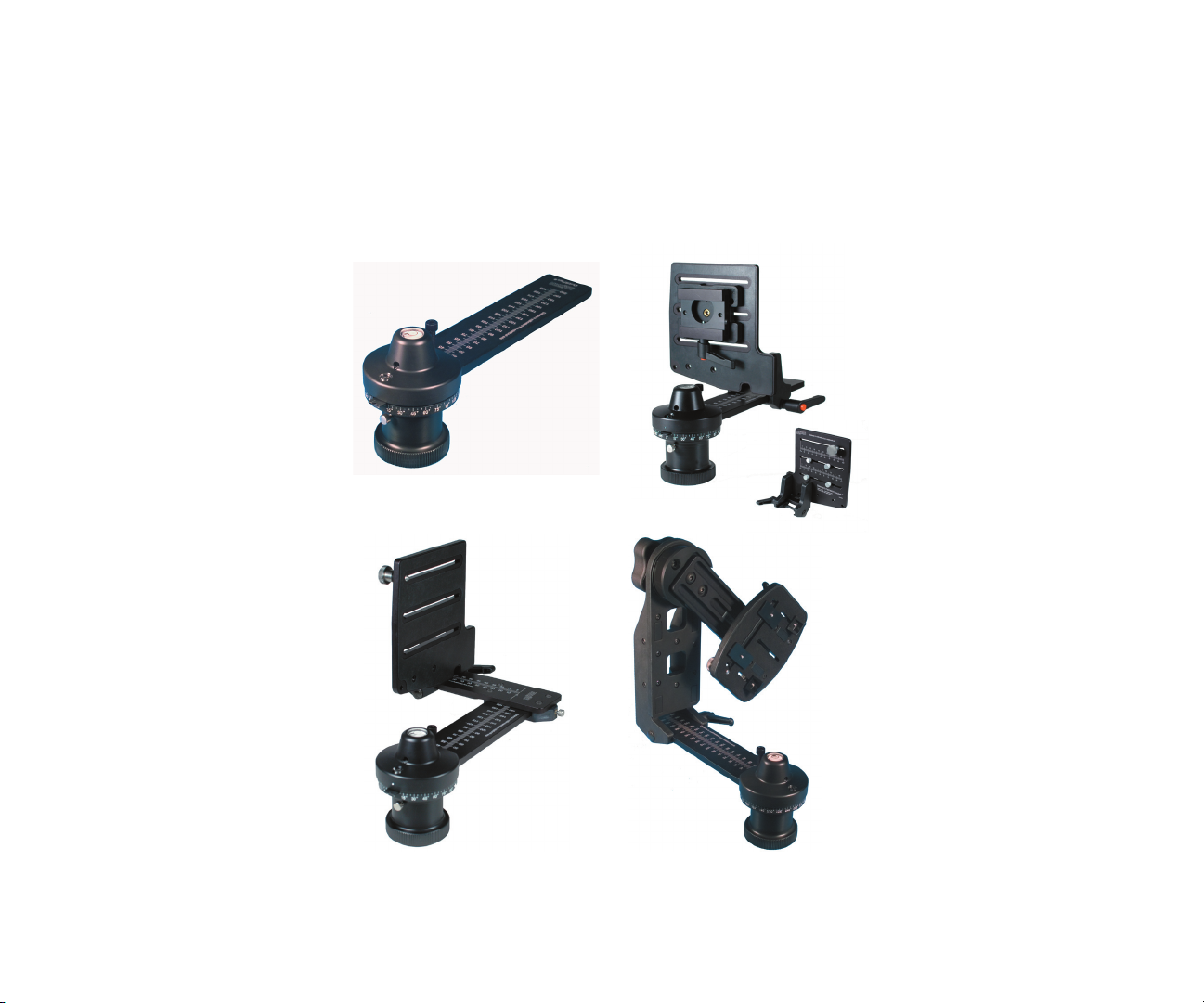
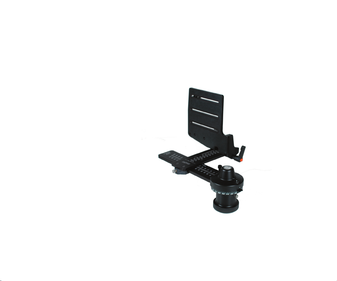
The QuickPan Family
sire two in de pen dent axes of ad just ment. It can be
with the Compact Camera Bracket. The two axes
than nec es sary. When a cam era equipped with a
the im age. This fea ture makes the Twin-Axis Adapter
VR Cubic pan ora mas. This bracket is ideal for
those soft ware ap pli ca tions that stitch mul ti ple
to sup port most dig i tal and fi lm cam er as in a
pact than previous models and the com pe ti tion.
will also ac cept older Kaidan camera brackets
Rotator Base (QuickPan )
Twin-Axis Adapter
Standard Camera Brack et
Spherical Camera Bracket
Page 4
QuickPan Rotator Base
the silver thumbscrew on
the side of the black Rotator
to remove the head from the
tripod.
Once the thumbscrew is
the Detent Disc can be
the Rotator Housing.
the re cessed area in the top
to fully engage and collapse
the plunger, then tight en the
thumbscrew.
the plung er so that the metal
that the plunger is not set
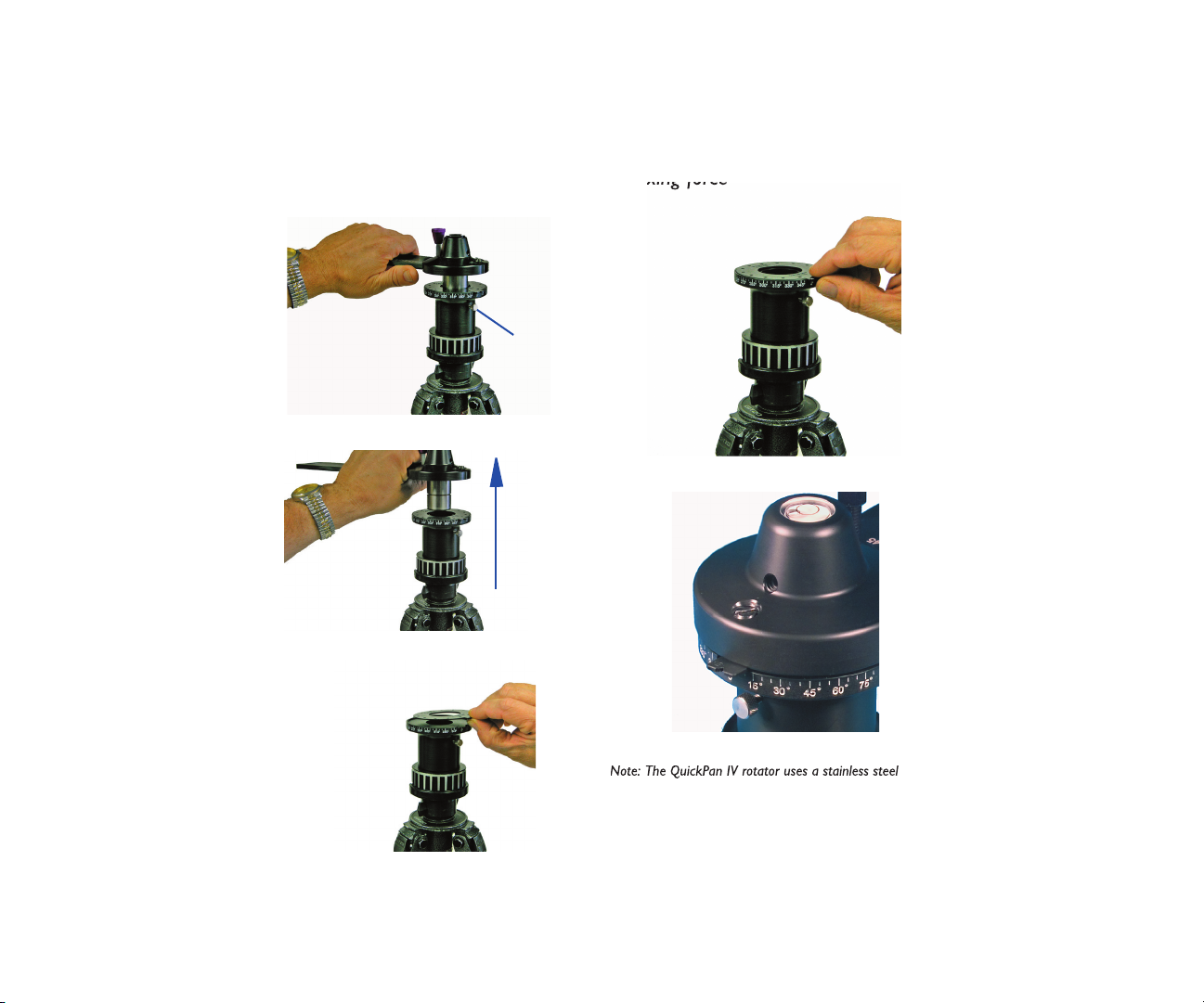
Installing Detent Discs
1)
2)
3)
Sil ver
Thumbscrew
4)
5)
Adjusting the Force
of the Spring Plunger
Page 5
QuickPan Rotator Base
with a tripod adapter bushing which ac-
tri pod mounts.
grab the lever and turn coun-
terclockwise. The clamp lever is
turned clockwise to tighten and
tioned by pulling outwards against
wise or counterclockwise. Next
throughout this manual showing
the mounting confi gurations of the
1/4 inch Tripod
3/8 inch Tripod
Page 6

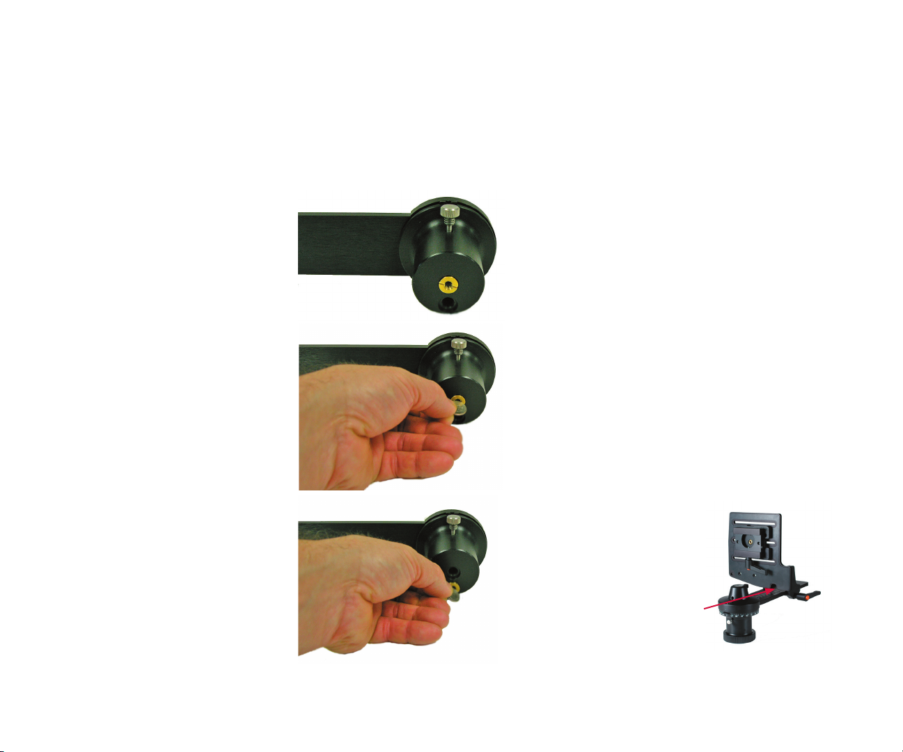
Standard Camera Bracket - Camera Mounting
Mounting your camera on the Stan dard Camera Bracket
the ap pro pri ate slot in the Ver ti cal
that has the thread ed hole. Care-
ful ly un screw the knob out of the
thread ed hole, be ing care ful not to
to wards the rear of the camera.
pro pri ate slot then into the tri pod
tight on the Vertical Brack et. Don’t
wor ry about get ting the cam era
you’ll need to do when you’re
your lens over the pivot point is
to lock the brack et in place. Note:
the lever and turn clockwise to
tighten and counterclockwise to
Page 7

Mounting your camera on the Spherical Bracket
which is held into po si tion by large
you to po si tion the arm and your
tightening the clamp lever. Note: The
the centerline of your cam era’s lens
with the center of the camera, it may
Spherical Camera Bracket - Camera Mount ing
that are provided for you to help
An optional camera mount is also
this case you would attach the a plate
Adjusting the camera position for the
the swing arm, or sliding the entire
the camera.
grab the lever and turn clockwise
to tighten and counterclockwise to
wise.
Page 8

Camera Mounting - Standard Camera Bracket
Mounting your camera on the camera brackets
the tri pod mounting thread on your
po si tion the camera knob to another
move the knob sim ply slide the knob
thread ed hole. Care ful ly un screw the
time, as this is a task you’ll need to do
when you’re ready to shoot.
your lens over the pivot point is ac-
com plished by loosening the clamp
tight en the clamp lever to lock the
sem bly along the arm of the Rotator
your cam era on the bracket and to
era when you use it for other tasks.
grab the lever and turn clockwise
to tighten and counterclockwise to
wise.
Page 9

Nodal Point
This is one of the most frequently
asked questions when it comes to
stitcher-based panorama creation.
Once you understand the basics,
you’ll be able to easily locate the
nodal point for any camera and
lens combination.
Simply put, the nodal point is the
point inside your camera where
the light rays converge and fl ip
over. When shooting a panorama
it’s necessary to rotate about
this point to eliminate the image
mismatch caused by parallax error.
It’s also worth noting that the
nodal point is not the same as
the fi lm plane, which is often
marked on the underneath side of
many 35mm cameras. Generally,
for most 35mm cameras and
lenses, the nodal point is located
somewhere towards the center of
the lens barrel.
Parallax error can be easily
demonstrated by this simple
experiment. Close one eye and
hold your index fi nger upright
Parallax error can be easily demonstrated. It’s the rel a tive movement caused by a shifting point of view. In this ex am ple, you eye
is moving with respect to your hand and the back ground.
about six inches away from your
open eye. Rock your head from
side to side. Notice how your
fi nger moves with respect to
the background. This relative
movement is due to the fact that
you’re not rotating your head
around your eye’s nodal point,
which is somewhere in the center
of your eyeball. Instead, you’re
rotating about your spine which
is several inches to the rear and
off to one side. It is this relative
side-to-side motion that we will
strive to eliminate when setting up
a camera for VR panoramas.
Step 1: The side-to-side adjustment
Once your camera is fastened to
your camera bracket, move to the
front of the tripod head so you’re
looking into the lens. Adjust the
camera bracket so that the cen ter
of the lens is di rect ly over the
pivot axis of the tripod head. Try
to be as accurate as possible. You
should strive to get this adjustment within plus/minus a 1/16th of
an inch.
Page 10

Nodal Point (continued)
Step 2: Fore-Aft Adjustment
This step is most easily
accomplished out of doors. Find
a vertical edge or line, such as a
doorway or edge of a building.
Position your camera and tripod
about 2-1/2 feet away, or as close
as possible with the edge still in
focus when you look through
the viewfi nder. If you’re using
a multirow head such as the
QuickPan III Spherical, set the
swing arm to a level horizontal
position (zero degrees).
Looking through the camera’s
viewfi nder, fi nd another vertical
edge or line that is far away, such
as another building or telephone
pole. Align the two objects and
rotate the pan head so they are in
the left hand side of the viewfi nder.
Rotate the pan head so the two
objects move over to the right
hand side of the viewfi nder. Unless
you’ve managed to unwittingly
locate the right position, you
should notice the two objects will
Looking through the viewfi nder align a close object (brick wall)
with a faraway ob ject (tele phone pole). As you ro tate the camera
from side-to-side there should be no relative move ment be tween
the two objects as shown to the right.
If, as shown above, the two objects move with re spect to one
and another in the viewinder, slide the camera fore or aft in
order to elim i nate this move ment. Here, the tele phone pole
has moved be hind the brick wall.
move with respect to each other
as you rotate the pan from left to
right. Slide the camera to the front
or rear as required to eliminate
this relative movement.
Step 3: Record Your Results
After you’ve discovered the two
location dimensions, be sure to
record the settings. The QuickPan
III has convenient indicator
scales for this purpose. These
numbers represent the nodal
point for this given camera and
lens combination. If you change
cameras or lenses, this procedure
may have to be repeated
Step 5: How About Rangefi nder
Cameras?
A rangefi nder camera is a
camera where you look through
a separate viewfi nder and not
through the actual lens. The
process is basically the same.
Locate the Side-to-Side adjustment
as discussed in Step 1. When it
Page 11

Nodal Point (continued)
comes to the Fore-Aft adjustment,
you won’t be able to look through
the viewfi nder to determine the
proper setting since the viewfi nder
is a separate optical path that
doesn’t really “see” the same image
as the fi lm.
Instead, you’ll have to start with
the bracket all the way to the
front and take pairs of test shots.
Each pair will have the vertically
aligned objects in the left and then
the right side of the viewfi nder.
After each pair of photos, slide the
bracket rearward and repeat the
process. Slide the bracket the same
increment each time (i.e. 10mm).
Be sure to record the scale setting
for each pair of images. Process
the fi lm, or in the case of digital
cameras, download the images to
your computer.
At the end of this process you will
be able locate the pair of images
with the least relative movement.
If no single image is optimum, you
may need to interpolate between
two images to fi nd the closest value.
Page 12

Shooting Panoramas
Apple recommended that the images
to one-half. That’s a good rule of thumb
How much Overlap?
How many Shots?
Once you’ve determined the overlap, you’ll
be able to fi gure out how many shots.
The easiest way to do this is to simply
look through the viewfi nder and turn the
camera to achieve the desired amount of
overlap. You then check the angle readout
to see how far you turned the camera.
Round the angular value to the nearest
convenient value. For most stitching
programs, it is generally not that important
to use a precise overlap value. However, it
should be noted that some programs are
more sensitive to an overlap value that
constantly repeats from shot to shot. You
may need to experiment somewhat to
obtain the best results.
Taking the Photos
When you’re ready to shoot, make sure
that the camera is securely attached to the
QuickPan III. You should use a tripod that is
sturdy, ideally one that has a center support
system of braces to help keep the camera
from fl exing.
Proper leveling is important and often
misunderstood. When it comes to leveling
there are two things that are fairly
important. With multirow panoramas
(i.e. Stitcher) the issue of leveling is less
crucial and primarily involves aestethics
and placement of the horizon. We’ll
concentrate primarily on cylindrical or
single-row panoramas.
First, the camera's optical axis should be
parallel with the rotation plane of the
tripod head. In other words the camera
should not be pointed up or down with
respect to the plane of rotation.
Secondly, it's also somewhat important for
the camera and fi lm/CCD to be properly
aligned with respect to rotation when
viewed from the front (looking into the
lens).
This can happen because the camera is not
seated fl ush against the upright bracket.
This is pretty common since many cameras
have mounting screws that are not in the
center of the base. Many cameras have
screws off to one end of the camera or at
the edge of the camera and this can cause
the camera to not be pulled down evenly
onto the tripod head mounting plate.
Another problem is that CCDs may not
be accurately positioned within the camera
body and respect to the mounting surface.
It only takes a fraction of degree and with
other manufacturing tolerances this can
add up to be noticeable.
This misalignment can also happen if the
upright bracket is bent or is not exactly
perpendicular to the rotation plane of the
head. At Kaidan we check this dimension
very closely to ensure it's as close to 90° as
reasonbly possible.
The effect of a rotated camera (when
viewed looking into the lens) is a
Page 13

Shooting Panoramas (continued)
stairstepping of images as you progress
around the panorama. Stairstepping has
nothing to do with the state of the entire
head being level with respect to the
horizon. This can be corrected by rotating
all the images a slight amount in your
authoring program.
You can also shim the camera/head to
compensate for such misalignment errors
as well. A few layers of tape is usually all
that it takes. Let me also reiterate what's
not as important as some people think.
The overall level of the head/camera is
not as critical in order to produce good
stitched results. As long as the camera is
not tilted or rotated and as long as the
camera is positioned so that the optical
axis is parallel to the rotation plane, you
can tilt or position the entire head so that
it's not level to the horizon and it won't
affect the image.
Now, it might produce a panorama that is
tilted with respect to the horizon but that
might be an artistic choice or something
you want to do on purpose.
rotation plane and the camera/CCD is not
rotated, slight variations in level as the head
rotates is generally not a problem.
As you shoot around the circle, try to
avoid capturing any moving objects that
might come into your fi eld of view. There
is no harm in waiting, for example, while
a person walks past before shooting the
photo.
You may also want to check with the
software developer of the stitching
software that you’re using to get their
recommendations for exposure settings
and other camera settings.
We hope you enjoy shooting your
panoramas and if you have any questions or
problems using our equipment, please let
us know.
As long as the optical axis is parallel to the
Page 14

Warranty and Product Return In for ma tion
to an oth er lan guage, for any purpose oth er than the lic ens ee’s personal use and
A • Limited Warranty
A • Limited Warranty
with new or re built parts for a period of three-hundred and six ty fi ve (365) days
will be cov ered by their re spec tive com pa ny’s prod uct war ran ty.
theory . All express and implied warranties, in clud ing the warranties of mer chant abil i ty
this prod uct, customer ac knowl edg es and agrees to these Lim its and Ex clu sions. If a
All Kaidan products come with a 30-day re turn pol i cy (a minimum 15 percent
with ap pro pri ate levels of ship ping insurance for the item being returned. Kaidan will
the con di tion of the prod uct (how the prod uct best meets the cri te ria above), at
di tions to the product.
their ship ping com pa ny.
to their regular Sug gest ed Re tail Price (SRP). The credit, to customer, will refl ect the
All shipping costs, VAT, duties and return costs are sole re spon si bil i ty of cus tom er. If
When returning a product, cus tom er must fi rst contact Kaidan (or the dis trib u tor/
the RMA#, cus tom er will be in struct ed to return product directly to Kaidan. Re turned
goods must be shipped with an ap proved traceable service, such as FedEx, and with
Attention: Return Department per RMA# ______
 Loading...