

FD-Repeater (KPI-2220E)
Operation manual
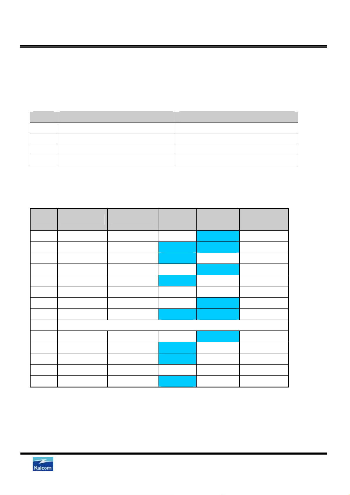
S.Y.Jun
Contact: syjun@kaicom.co.kr
#109, Gayang Techno Town 1487, Gayang-dong, Kangso-gu, Seoul, Korea
Tel: +82-2-6734-6777 Fax: +82-2-6734-6776
Kaicom Co., Ltd.
Kaicom Confidential
Revision History
Revision Description of Change Date Author
1.0 Initial June. 01.06 S.Y.Jun
KB-MMU-06-Manual_2220E-1.0
FCC Notice:
Any changes or modifications not expressly approved by Kaicom could void
the user's authority to operate the equipment.
Kaicom Co., Ltd.
Sheet2/15

Kaicom Confidential
KB-MMU-06-Manual_2220E-1.0
TABLE OF CONTENTS
1. Main description ..........................................................................................................................4
2. Hardware Block diagram.............................................................................................................5
3. Interface description....................................................................................................................5
4. Setting up the module to slave mode ........................................................................................6
5. Setting up the module to master mode .....................................................................................6
6. Setting up the module to TD repeater mode .............................................................................7
7. Operation modes .........................................................................................................................8
8. Operation modes table................................................................................................................8
9. Built-in filters................................................................................................................................9
10. Mapping table of module and mode.........................................................................................9
11. Mapping of mode and module................................................................................................10
12. Using built-in LV coupler ........................................................................................................11
13. Installation example (MV FD repeater)...................................................................................13
14. Installation example (MV TD repeater & LV Head-End)........................................................14
15. Installation example (MV Slave & LV Head-End) ..................................................................15
Kaicom Co., Ltd.
Sheet3/15

1.Main description
¾ Model name: KPI-2220E
¾ Chipsets: DSS 9002 x 2
¾ Main Function:
1. FD Repeater
2. MV TD Repeater and LV Head-End
¾ Interface:
Internal
• Port iL: BNC Connector
Kaicom Confidential
KB-MMU-06-Manual_2220E-1.0
• Console: RJ11
External
• Port A: F-Type Connector (IP 67~68)
• Port B: F-Type Connector (IP 67~68)
• Port L: F-Type Connector (IP 67~68)
• Ethernet: RJ45 x 2 EA (IP 67~68)
¾ Power Input:
• 90 ~ 265V AC, 50/60Hz
¾ Main features:
• Built-in filters
• Built-in LV coupler
• IP 67~68
Kaicom Co., Ltd.
Sheet4/15
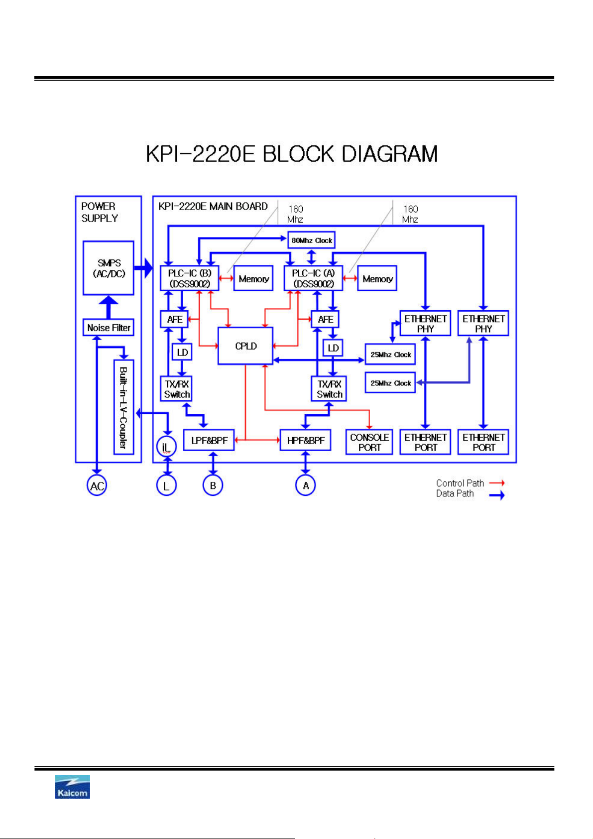
2.Hardware Block diagram
Kaicom Confidential
KB-MMU-06-Manual_2220E-1.0
3.Interface description
a. Internal interface
9 Port iL: Signal port of LV coupler
9 Console: con sole p ort for management, RJ11interface
b. External interface
9 Port A: Signal port to connect powerline(MV or LV) with coupler
9 Port B: Signal port to connect powerline(MV or LV) with coupler
9 Port L: Signal port to connect powerline(LV only) with built-in LV-coupler
9 Ethernet: Ethernet port of 10/100Mbps, RJ45 interface
Kaicom Co., Ltd.
Sheet5/15

Kaicom Confidential
KB-MMU-06-Manual_2220E-1.0
4.Setting up the module to slave mode
a. For more information about console set-up, please refer to console manual.
b. Use a TAB Key to move your desired module.
c. Set up the booting mode to NVRAM.
9 #admin/>ac b m NVRAM
d. Set up the management IP address.
9 #admin/>a c d hcp disable
9 #admin/>net i p ip 192 168 100 1
9 #admin/>net i p nm 255 255 0 0
9 #admin/>net i p gw 192 168 0 1
e. Set up the module to slave.
9 #admin/>ma c c n s
5.Setting up the module to master mode
a. For more information about console set-up, please refer to console manual
b. Use a TAB Key to move your desired module.
c. Set up the booting mode to NVRAM
9 #admin/>ac b m NVRAM
d. Set up the management IP address.
9 #admin/>ac dhcp disable
9 #admin/>net ip ip 192 16 8 100 1
9 #admin/>net ip nm 255 255 0 0
9 #admin/>net ip gw 19 2 168 0 1
e. Set up the module to master
9 #admin/>mac c n m
f. Set up the frequency mode.
9 #admin/>syn c m w 3
Kaicom Co., Ltd.
Sheet6/15

Kaicom Confidential
KB-MMU-06-Manual_2220E-1.0
6.Setting up the module to TD repeater mode
a. For more information about console set-up, please refer to console manual
b. Use a TAB key to move your desired module.
c. Set up the booting mode to NVRAM
9 #admin/>ac bm NVRAM
d. Set up the management IP address
9 #admin/>ac dhcp disable
9 #admin/>net ip ip 192 16 8 100 1
9 #admin/>net ip nm 255 255 0 0
9 #admin/>net ip gw 19 2 168 0 1
e. Set up the module to TD repeater
9 #admin/>ma c c n r
Kaicom Co., Ltd.
Sheet7/15
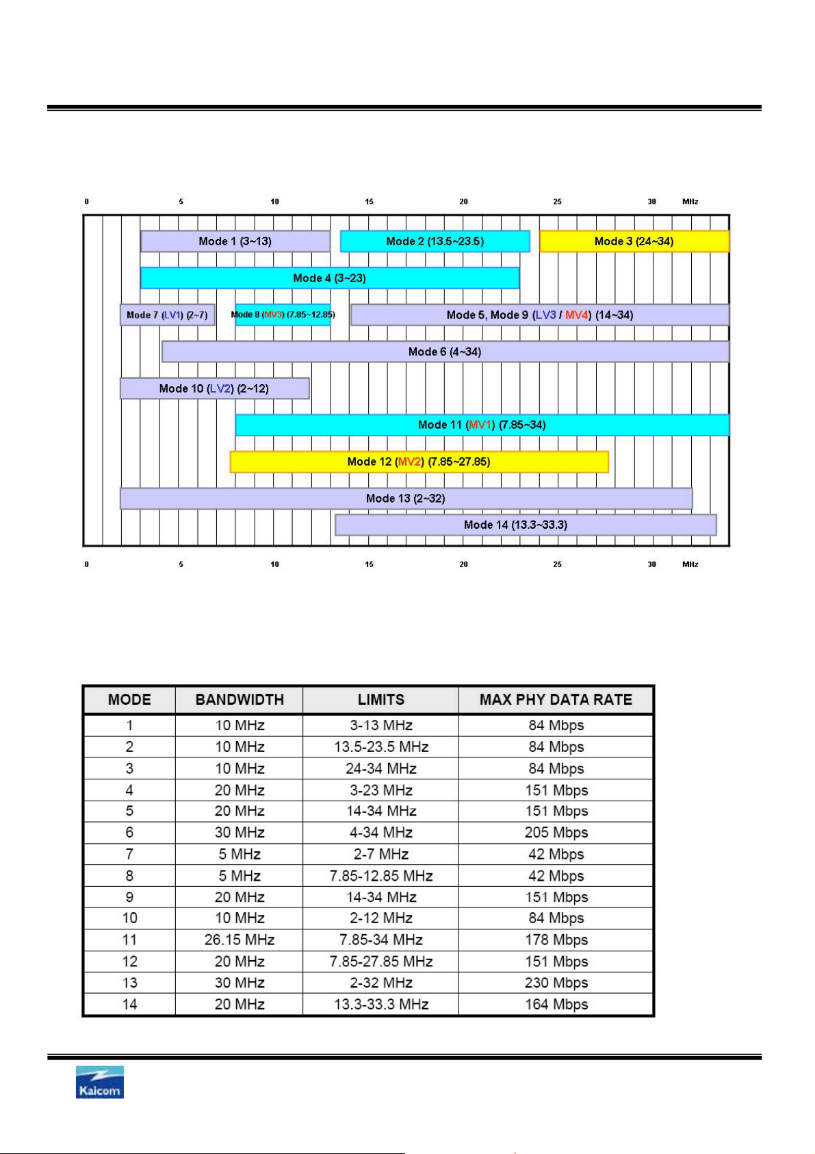
7.Operation modes
Kaicom Confidential
KB-MMU-06-Manual_2220E-1.0
8.Operation modes table
Kaicom Co., Ltd.
Sheet8/15
Kaicom Confidential
KB-MMU-06-Manual_2220E-1.0
9.Built-in filters
Module A is consisted of 7, 13 and 23 MHz high pass filters and 13.5~23.5 MHz band pass filter.
Module B is consisted of 7, 13 and 23 MHz low pass filters and 13.5~23.5 MHz band pass filter.
Index Module A Module B
1
2
3
4
7MHz high pass filter 7MHz low pass filter
13MHz high pass filter 13MHz low pass filter
23MHz high pass filter 23MHz low pass filter
13.5~23.5MHz band pass filter 13.5~23.5MHz band pass filter
10.Mapping table of module and mode.
MODE BANDWIDTH LIMITS(MHz)
MODULE A MODULE
B
1 10 3-13 X O 84
2 10 13.5-23.5 O O 84
3 10 24-34 O X 84
4 20 3-23 X O 151
5 20 14-34 O X 151
6 30 4-34 X X 205
MAX PHY
DATA RATE
7 5 2-7 X O 42
8 5 7.85-12.85 O O 42
9 Not valid
10 10 2-12 X O 84
11 26.15 7.85-34 O X 178
12 20 7.85-27.85 O X 151
13 30 2-32 X X 230
14 20 13.3-33.3 O X 164
Kaicom Co., Ltd.
Sheet9/15

Kaicom Confidential
KB-MMU-06-Manual_2220E-1.0
11.Mapping of mode and module
Please refer to “Available mapping table of module and mode” to allocate a mode to module.
Mode (1, 4, 7 and 10) can be used in module B.
Mode (3, 5, 11 and 12) can be used in module A.
Mode (2 and 8) can be used in module A and B all together.
Example of FD network configuration.
P1 P1 P1 P1
HE
Mode 1 Mode 3
FD FD FD FD
Mode 2
Mode 1
Mode 1 block must be used only module B.
P1 P1 P1 P1 P1
Mode 1
HE
FD FD FD FD
Mode 2
Mode 3
B B B
Mode 1
Mode 3 block must be used only module A.
P1 P1 P1 P1 P1
Mode 1
Mode 2
Mode 3
Mode 1
P1
HE
FD FD FD FD
A B A B B
Mode 2 block must be used module A or B that wasn’t used in mode 1 or mode 3.
P1 P1 P1 P1 P1
Mode 1
HE
FD FD FD FD
Mode 2
Mode 3
B A B A A B B
Mode 1
Kaicom Co., Ltd.
Sheet10/15

Kaicom Confidential
KB-MMU-06-Manual_2220E-1.0
12.Using built-in LV coupler
a. In order to use built-in LV coupler, PLC signal should be transmitted through AC power
inlet.
Power module
Built-in coupler
Port A
Port B
Port L
PLC signal
b. To use LV coupler
9 Port L is reserved for LV powerline.
9 Connect the coaxial cable from port L to port A or Port L to port B (that you desired).
c. There are two cases to use built-in LV coupler.
9 Connect port A to port L with BNC cable, when using mode (2,3,5,8,11,12,14) in LV block.
LV power line
9 Connect port B to port L with BNC cable, when using mode (1,2,4,7,8,10) in LV block.
Kaicom Co., Ltd.
Sheet11/15

Kaicom Confidential
Figure of Tx/Rx of PLC signal between AC power inlet and module A.
KB-MMU-06-Manual_2220E-1.0
Figure of Tx/Rx of PLC signal between AC power inlet and module B.
Power module
Built-in coupler
Power module
Built-in coupler
PLC signal
Port A
Port B
Port L
LV power line
Port A
Port B
Port L
Coaxial cable
Coaxial cable
PLC signal
Kaicom Co., Ltd.
LV power line
Sheet12/15

A
Kaicom Confidential
KB-MMU-06-Manual_2220E-1.0
13.Installation example (MV FD repeater)
MV # 1 MV # 2
Mode Mode 3 Mode 2
Module Module A Module B
Coupler MV capacitive coupler MV capacitive coupler
MV # 1 MV # 2
Mode 3
MASTER SLAVE
MV coupler
Port A Port B
Power supply
Module
Power
module
Mode 2
Port iB Port iA
Module B
a. External interface setting.
9 Port A and port B should be connected to each their coupler by coaxial cable.
b. Setting up the FD repeater
9 Module A should be configured with “M V # 1(mode 3)”.
9 Module A should be configured as SLAVE.
9 Module B should be configured with “MV # 2(mode 2)”.
9 Module B should be configured as MAS TER.
9 Module B should be configured in mode 2.
Kaicom Co., Ltd.
Sheet13/15

Kaicom Confidential
KB-MMU-06-Manual_2220E-1.0
14.Installation example (MV TD repeater & LV Head-End)
Mode Mode 2 Mode 7
Module Module A Module B
Coupler MV capacitive coupler Built-in LV coupler
MASTER SLAVE
MV coupler
Module A
Module B
Power
module
MV LV
MV
Mode 2
Transformer
LV
Port A
Mode 7
Port B
Port L
a. External interface setting
9 Port A should be connected to coupl er.
9 Port L and port B should be connected each other by
b. he FD repeater
Setting up t
9 Module B should be config
9 Module B should be configured as MAS TER.
9 Module A should be configured with “M V (mod
9 Module A should be configured as T D REPEATER.
9 Module A will auto detect frequency mode.
Power supply & LV signal
using coaxial cable.
ured with “LV (mode 7)”.
e 3)”.
Kaicom Co., Ltd.
Sheet14/15

Kaicom Confidential
KB-MMU-06-Manual_2220E-1.0
15.Installation example (MV Slave & LV Head-End)
Mode Mode 2 Mode 7
Module Module A Module B
Coupler MV capacitive coupler Built-in LV coupler
MASTER
MV coupler
Module A
Module B
Power
module
MV LV
MV
Mode 2
Transformer
LV
Port A
Mode 7
Port B
Port L
c. External interface setting
9 Port A should be connected to coupl er.
9 Port L and port B should be connected each other by
d. he FD repeater
Setting up t
9 Module B should be config
9 Module B should be configured as MAS TER.
9 Module A should be configured with “M V (mod
9 Module A should be configured as SLAVE.
9 Module A will auto detect frequency mode.
Power supply & LV signal
using coaxial cable.
ured with “LV (mode 7)”.
e 3)”.
Kaicom Co., Ltd.
Sheet15/15

Hardware Installation manual
PLC Device (KPI series)
S.Y.Jun
Contact: support@kaicom.co.kr
#109, Gayang Techno Town 1487, Gayang-dong, Kangso-gu, Seoul, Korea
Tel: +82-2-6734-6777 Fax: +82-2-6734-6776
Kaicom Co., Ltd.

Kaicom Confidential
Revision History
Revision Description of Change Date Author
1.0 Initial July. 1.06 S.Y.Jun
1.1 Revision July.18.06 S.Y.Jun
1.2 Revision Nov.21.06 S.Y.Jun
KB-MMU-06-Hardware
Installation Manual-1.2
FCC Notice:
Any changes or modifications not expressly approved by Kaicom could void
the user's authority to operate the equipment.
Kaicom Co., Ltd.
Sheet2/12

Kaicom Confidential
KB-MMU-06-Hardware
Installation Manual-1.2
TABLE OF CONTENTS
1. Objectives.....................................................................................................................................4
2. Overview.......................................................................................................................................4
3. Hardware Features.......................................................................................................................4
4. Unpacking the PLC device..........................................................................................................6
5. Tools and materials.....................................................................................................................6
6. Mounting the PLC device............................................................................................................7
7. How to connect coupler cable with coupler............................................................................11
8. What to do next..........................................................................................................................12
Kaicom Co., Ltd.
Sheet3/12

Kaicom Confidential
KB-MMU-06-Hardware
Installation Manual-1.2
1.Objectives
This publication explains the steps for installing the KPI Series Outdoor PLC(Power Line
Communication) devices, and includes detailed instructions for mounting the device.
2.Overview
The KPI Series PLC device (hereafter called the PLC device) is a network device designed to
communicate with power line.
The PLC device is a standalone unit that can be mounted on an electric pole or cabinet where
a subterranean line or streetlight pole or on a building wall or overhang. The PLC device can
be installed where power is available.
The PLC device provides power line mesh backhaul that supports 200 Mbps data rates.
The PLC device is configured, monitored, and operated through a Web or Telnet or Console as
described in the Operation Manual.
3.Hardware Features
a. Connectors : The PLC device supports five connectors (see Figure 1):
9 Port A: F-Type Connector
9 Port B: F-Type Connector
9 Port L: F-Type Connector
9 Ethernet: RJ45 x 2 EA
9 AC power connector
Figure 1. Connectors
Kaicom Co., Ltd.
Sheet4/12

b. Power Sources
The PLC Device can be powered by AC power 90 ~ 265V AC, 50/60Hz.
Customer-supplied AC power cord is 36-ft (11-m) for use in the US and Canada.
c. Ethernet Port
The PLC Device’s Ethernet port uses a 8 pin,RJ-45 connector, linking the PLC Device to
your 10BASE-T or 100BASE-T Ethernet LAN.
The Ethernet cables are used to send and receive Ethernet data.
d. Port A
Signal port to connect MV/LV power line with coupler
Kaicom Confidential
KB-MMU-06-Hardware
Installation Manual-1.2
e. Port B
Port B: Signal port to connect MV/LV power line with coupler
f. Port L
Signal port to use built-in LV coupler.
g. Metal Enclosure
The PLC device uses a metal enclosure that can accommodate both indoor or outdoor
operating environments and IP68 requirements.
Kaicom Co., Ltd.
Sheet5/12

Kaicom Confidential
KB-MMU-06-Hardware
Installation Manual-1.2
4.Unpacking the PLC device
Follow these steps to unpack the PLC device:
Step 1 Open the shipping container and carefully remove the contents.
Step 2 Return all packing materials to the shipping container and save it.
Step 3 Ensure that all items listed in Package Contents are included in the shipment. If any
item is damaged or missing, notify your authorized Kaicom sales representative.
a. Package Contents
Each PLC device package contains the following items:
9 PLC device
9 Ethernet Cable
9 Power Code
9 Wall Mount Kit
9 Pole Mount Kit
5.Tools and materials
To install the PLC device you will need the following:
• Tool set(wrenches or socket set and a drill etc)
• Customer-supplied AC Power cord
• Customer-supplied Mount Kit
• Customer-supplied Ethernet Cable
• Optional copper ground wire
• Optional coupler and coupler cable
• Optional ladder, power lift, rope, or other tools as required
Kaicom Co., Ltd.
Sheet6/12

Kaicom Confidential
KB-MMU-06-Hardware
Installation Manual-1.2
6.Mounting the PLC device
This section provides instructions for installing your PLC device.
There are two common installation methods: a wall installation using the wall mount kit
(supplied) or a pole installation using the pole mount kit(supplied).
a. Mounting the PLC device on a Pole
When installing an PLC device on a pole, you should use the Kaicom pole mount kit.
To mount the PLC device on a pole, perform these steps:
Step 1 From the pole mount kit, use four of the supplied short bolts to attach the pole
mount kit plate(Figure 2) to the PLC device mounting plate as shown Figure 3.
Figure 2.Pole mount kit plate Figure 3. PLC device mounting plate
Kaicom Co., Ltd.
Sheet7/12

Kaicom Confidential
KB-MMU-06-Hardware
Installation Manual-1.2
Figure 4. Attach a pole mount kit to PLC
Step 2. Select a mounting location. You can attach the PLC device(Figure 4) to any pole
where you want.
Step 3. Mounting a PLC device to a pole.(Figure 5)
Figure 5.Mounting to a pole
Kaicom Co., Ltd.
Sheet8/12

Kaicom Confidential
KB-MMU-06-Hardware
Installation Manual-1.2
b. Mounting the PLC device on a wall
When installing an PLC device on a wall, you should use the Kaicom wall mount kit.
To mount the PLC device on a wall, perform these steps:
Step 1 From the wall mount kit, use eight of the supplied short bolts to attach the wall
mount kit plate(Figure 6) to the PLC device mounting plate as shown Figure 7.
Figure 7. PLC device mounting plate
Figure 6.Wall mount kit plate
Kaicom Co., Ltd.
Sheet9/12

Kaicom Confidential
KB-MMU-06-Hardware
Installation Manual-1.2
Figure 8. Attach a pole mount kit to PLC
Step 2. Select a mounting location. You can attach the PLC device(Figure 8) to any wall
where you want.
Step 3. Mounting a PLC device to a wall.(Figure 9)
Figure 9. PLC device mounting plate
Kaicom Co., Ltd.
Sheet10/12

Kaicom Confidential
7.How to connect signal cable to the coupler unit
Connect the signal cable to the coupler unit referring to below figure 10.
Use the signal cable which is assembled with 10 pieces of ferrite core like below.
Figure 10. PLC device coupling
Coupler unit
KB-MMU-06-Hardware
Installation Manual-1.2
MV Line(Overhead)
Stopper
Signal
cable
Ferrite core
(Part No:
SN-20 OP 18.4 x 28.0 x 9.5HSN-20
or Equivalent)
Kaicom Co., Ltd.
Sheet11/12

Kaicom Confidential
KB-MMU-06-Hardware
Installation Manual-1.2
8.What to do next
Refer to the Operation Guide for more information on configuring, monitoring, and operating
your PLC device.
Kaicom Co., Ltd.
Sheet12/12
 Loading...