

Page 1
CaMMUNiCATIONSr
INC.
Addendum to
This addendum
well as providing updates for software enhancements made since the Guide was printed.
Add the following paragraph to Page
This Installation and Operation Guide is not intended to provide a comprehensive
explanation of every radio control
settings
the KC505
It is possible to generate
User
current
using the file manager (Windows
processor. The
In addition,
operating tips, are provided
Kachina
charge from the web site,
versions of the control
enhancements.
corrects
may be found in the on-screen User Guide, which may be accessed from within
control software by selecting
Guide,
then select a topic. Once the topic is displayed, press @ to send the
page to your printer. Printing the User Guide in its entirety is best accomplished
User
a
complete theory
also
has a policy of allowing
errors
Guide
505DSP
or
omissions
printed pages of the
file,
on
so
software
Installation and Operation Guide
in
the 505DSP Installation and Operation Guide,
3,
Section
and function. Full details of individual controls and their
3.1)
KC5O5.MAN, is in
of
operation, and application notes containing useful
Kachina’s internet web site at http://www. kachina-az.com.
we suggest you check there periodically for updated
and
1
-
Intoduction:
User
Guide
User
or
WordPad (Windows
you
to download many
announcements regarding other product
from the
Guide.
ASCii
Help
From
95),
format.
software
menu.
the Help menu select
or your word
upgrades free of
as
In
preparing this manual, an assumption has been made that the user is already farniliar
with Windows
provided with these
Add to
Correction to Page
Correction to Page
Page
4,
Section
4-Ohm external speaker is recommended.
Control
switch and microphone, speaker,
install
available from Kachina.
The functions of pins
AMP PTT.
Head
it in an unused drive bay of your
3.1,
5,
Section
-
I I,
Figure
95
or
NT
operating systems. If not, you should refer to the manuals
programs
3
-
Hardware Requirements:
5
The
505DSP
70,
11
for
further information.
-
Last Paragraph should read:
is
supplied with
Morse
ACC3
and
Extemal
13
are reversed
a
control head containing the main power
key and phone jacks.
PC,
while cables aliowing outboard use are
Power
Amplifier
in
the Guide. Pin
Cables
Connector
11
is
are provided to
chart:
VR
while
Pin
13
is
Page 2

Add
to Page
12,
Section
The control software may not be opened a second time if already running on the same
Com port. You can still start the software a second time on
however,
allowing you to control up to four radios in separate windows if you wish.
9
-
Control
Software
Installation:
a
different Com port,
Correction
following:
Current
current transceiver settings is displayed. Beginning with software version
the listed
Within this window, you must click on the green or yellow text to initiate
Clicking on White
using the pull
elsewhere in this Guide.
A
word
control program, antenna Smith chart,
select a window by clicking your mouse anywhere in the window, but you must be careful
not to click on these settings when you intend only to activate the control panel window.
Add
to
Section
Note:
Guide. This Guide
Coarse
frequency display to provide
currently selected band. Clicking or dragging your left
cause the receiver frequency to change. This slider
confirmation
to
Page
13
-
Replace
Settings Window
settings can be changed simply by clicking on the item you wish to access.
or
-
down menus and many also have dedicated “shortcut” keys, explained
of
caution
10
-
Additional details relating to
Tuning
when you have several windows active at the same time, i.e. the
Operation:
Slide
of where in the current band you are tuned.
Paragraph
-
When in the
gray text
may
Bar
Will
be accessed by selecting User Guide
for
a
entitled %urrent
KC505
have no affect. These settings can also
KCLOG,
all
functions may be found in the on-screen User
RX Tuning
convenient way to quickly change frequency within the
-
control program, a window showing the
etc.
A
slide bar is displayed above the receive
Settings
It
is a WindowP convention
mouse
also
Wndow“
from
the Help menu.
button in the slide bar
serves as a convenient visual
with
1
.x3,
a
change.
be
the
most of
changed
to
Will
Speech
This feature
headphones, allowing you to hear what
or
Will
have
separate slide bar. Settings
If using an 8
too low.
speakers are equally efficient.
the
signal is
Muting
or
note
Monitor - The speech monitor control may be accessed from the
allows
TX equalization, have on your signal. When
appear to allow adjustment
a
different volume setting for
-
Ohm external
Use
actual transmitted signal. Speech monitor audio is 8 bit digital
16
bit.
the
Receiver
off.
The receive meter
that VOX
your transmitted signal to be heard through the loudspeaker
affect
other settings, such as speech processor
speech
of
the speakerphones volume. Since you may wish to
CW
sidetone, selecting
of
both slide bars are retained independently in memory.
speaker
of a 4-Ohm speaker
-
The
.del
Will
is
disabled whenever the receiver is muted.
you may find that the
Will
give twice the audio output, assuming that both
Also
note that speech monitor audio quality
key on the numeric keypad toggles receiver muting on
display
“MUTE”
whenever muting is on.
monitor
on
sidetone
speech
monitor audio level
TX
menu.
or
is selected, a slider
Will
enable
while
the transmitted
It
is important to
is
inferior
a
is
to
Page 3

Mic/CW
from the TXmenu
output in both voice and
if you experience low TX power output.
Gain Control
or
-
The Mic/CW gain
pressing
m.
The
CW
modes. The Mic/CWgain level may need
control
Mic/CW
may be
gain setting affects the transmitter power
accessed
by selecting
to
be increased
Mic
Memory
settings. These channels are divided into
comprised of channels
memory
guide for details on how to save and recall
Scanning
menu. The transceiver can be commanded to scan groups
numbered 1
between 2 selectable frequency ranges. See the on-screen User Guide for further
d
eta
Bandpass
100
"O"
in the current settings window.
dedicated
Bandwidth for both data filters is
than the displayed receive frequency.
than the displayed receive frequency. The center frequency can be altered using the
shift control.
Channels
features are selected
Memory
through
i
I
s
.
Filters
kHz to
(zero)
3.5
kHz
shortcut
as
data filters. The center frequencies (fc)
Hi
DAT
DAT Med fc=
For
example:
and
Groups
1-20,
Channels
5,
stored in memory. Alternatively, the scan can
-
The
505DSP
in width. These may be selected from the
key on the numeric keypad
fc
=
-
100
memory channels are available for storing radio
5
groups of
group 2 contains channels
from
the
and
2210
1700
Channel
Groups
incorporates 11
Two
of
these filters, labeled
Hz
Hrz
500
Hz.
On
On
menu. Refer to the on-screen user
memory channels and groups.
-
Scanning is initiated under the
or
by ciicking the mouse on the
LSB
USB
the
20
channels. Group 1 is
21-40
DSP
bandpass filters ranging from
of
the
the fc
will
fc
will
be
and so on. The channel
Channel
of
up to
20
channels,
be
conducted
Filters
DAT
data
be 1700
1700 or 2210
menu, by using the
Hi
and
DAT
Med,
filters are:
or
2210 Hz lower
Hz
BPF
higher
value
are
IF
IF
shift
=
-
1000
Hz
DAT
Hi new fc
DAT Low new fc
Notch
automatically by selecting
between manual and automatic notch, or by clicking on the notch value in the current
settings window. A horizontal slide bar will appear whenever manual notch is selected.
Adjust
slide bar
screen
Notch width
(80
because
Zero
frequency, using 1 Hz
function.
Filter
-
The
the slide bar to select the notch center frequency. Clicking the mouse
will
always disable automatic notch and enable manual notch. See the on
User's
Hz)
and narrow
the notch in a wider mode, then sharpen
Guide for further details.
is
selected from the Filters menu. The choices
the slot is extremely sharp, it may be difficult to fit over the interfering signal.
is
2210-1000 = 1210
is
1700-1000
505DSP
notch filter may be programmed to operate manually
Notch
(40
Hz).
When the notch width
steps.
Practice
Hz
=
700
Hz
from the
Fi/ters
menu, by pressing
are
is
set
to narrow,
it
while
tuning the receiver about
is required here to obtain the most
Shift
Wide (160
be
wamed that
or
plus n to toggle
on
the
-
Hz),
medium
the
from
this
Page 4
CW
Tx
Buffers - The
memories.
CWmenu. Select
mouse
To
store a message in one of the CW buffers, select
which of the nine buffers you wish to transmit by clicking the left
button on the appropriate number. Your message
buffer when you click
transmitted
keypad.
as
Note:
CW
by pressing the
You
505DSP
OK
or
must be
has nine, 59-character,
depress the
in
C
W
Enter
key. Any one of the buffers can be
Ctrl
key plus a number 1 through 9 on the numeric
mode
to
transmit
a
CW
message buffers
C
Will
be stored to the selected
C
W
Tx
buffer.
W
Tx
Buffers
or
from the
Frequency
changes
Display
Reverse
Video
-
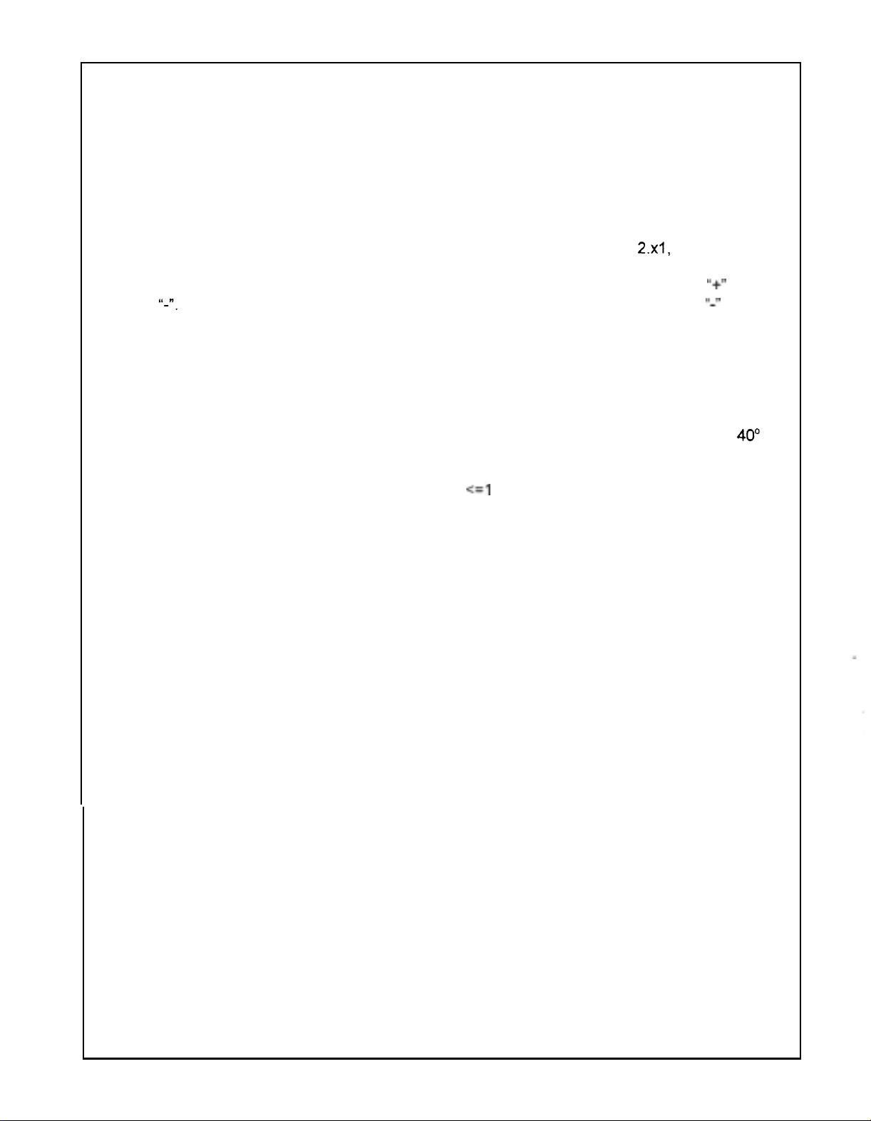
Beginning with software version
2.~1,
several
that affect the frequency display have been incorporated. First, the "up/down"
buttons that identify the currently selected tuning digit have been replaced with a
Il-".
If
tuning with a mouse, click on the
rnove the frequency downward. Second, to increase the visibility
selected digit, you may now choose to display
yellow, or normal video green. This is accomplished
the
Special
Two-speed
The fan
C, at which time the fan
temperature fault message
menu.
Cooling
Will
normally operate at low speed unless the heat sink temperature exceeds
Fan
Will
-
The
505DSP
switch automaticaily to high speed operation and a
Will
light. This message
operator reduces transmitter power output to
-
telemetry goes off
or the radio has been exposed
autornobile parked
VSWR
Alarm
line. A temperature fault message normally occurs only if the fan fails
to high temperatures, such as found in an enclosed
in direct cunlight.
-
If the antenna VSWR exceeds
above the transmit meter when transrnitting. If the
Will
be
alarm
VSWR
the
yellow in color.
exceeds
3:l
If
the VSWR is above
you should discontinue transmission and
"+"
to move the frequency upward,
of
the currently
it
in reverse video green, reverse video
by selecting
is
equipped with a two-speed cooling fan.
Will
remain on screen until the
<=I
O
watts,
2:1, a
VSWR
presses the Reset button or
VSWR alarm
is between
3:1,
the alarm
Tuning
will
be displayed
2:l
Will
be red in
check
the antenna for
or
Digit
and
the
Color from
3:1,
faults.
'I+"
and
IL-I'
to
-
the
color.
40"
If
Setting
the
Parallel
(Printer)
the parallel port select
Set
Port
Printer
-
You may
fort
from the
select
Special
parallel port 1, 2 or 3. To change
menu.
Page 5

KACHINA COMMUNICATIONS, INC.
LIMITED
Kachina Communications, Inc. (“Kachina”) warrants its amateur radios, accessories and options, as follows:
PERIOD
This warranty
WHO
IS
This warranty is enforceable only by the original purchaser.
WHAT
Except as specified below, this Warranty covers all defects in materials and workmanship in Kachina amateur radios,
accessories and options. The following are not covered by the warranty:
1.
2.
3. Any unit which is not new when
WHAT WE WILL PAY FOR AND WHAT YOU MUST PAY FOR
Kachina
product for Warranty service, you are responsible for the initial shipping charges, but, within the United States of
America only, excluding Puerto Rico and other territories, we Will
repaired
vehicle or other site
HOW TO OBTAIN WARRANTY SERVICE
Within the United States your Kachina amateur radio, accessory
Communications, Inc. , Attention: Service Department,
the U.S.A., the radio may be serviced by any authorized Kachina Amateur Radio Dealer or Service Center.
Whenever
of purchase. If you have difficulty obtaining service, please write
Box
1949,
mail address: [email protected].
LIMITATION
ALL IMPLIED WARRANTIES, INCLUDING WARRANTIES
PARTICULAR PURPOSE,
EXCLUSION
KACHINA’S LIABILITY
SHALL
BECAUSE
POSSIBILITY OF SUCH DAMAGES.
SOME
NOT ALLOW THE EXCLUSION OF INCIDENTAL OR CONSEQUENTIAL DAMAGES,
LIMITATIONS AND EXCLUSIONS MAY NOT APPLY TO YOU.
This warranty gives you specific legal rights, and you may also
This warranty is enforceable only if the product has been purchased in the United States of America.
WARRANTY
OF
THE WARRANTY
Will
remain in effect for
PROTECTED
IS
COVERED AND WHAT
Damage, deterioration
a. Accident, misuse, abuse, neglect, unauthorized product modification
contained in your Installation and Operation Guide.
b.
Water or other elements.
c. Repair
d. Installation of parts
e. Installation of accessories or options from other manufacturers.
Damage
modified
Will
or
replaced under Warranty. You are responsible for any charges incurred in removing the product from the
a
Cottonwood, Arizona, 86326, U.S.A., telephone:
NOT BE LIABLE FOR ANY DAMAGES, WHETHER INCIDENTAL, CONSEQUENTIAL
OF
STATES DO NOT ALLOW LIMITATIONS ON HOW LONG AN IMPLIED WARRANTY LASTS AND/OR DO
or attempted repair by anyone not authorired by Kachina.
or
accessories.
or
loss
occurring during shipment of the product (claims must be presented to the carrier).
or
removed.
pay all labor and material expenses
of
use and
product is presented for warranty service, you must supply a sales receipt
OF
IMPLIED WARRANTIES
OF
DAMAGES
IS
LIMITED TO REPAIR
ANY DEFECTIVE KACHINA PRODUCT, EVEN IF KACHINA HAS BEEN ADVISED OF THE
ON
AMATEUR RADIOS,
two
(2) years from the date of purchase by the original purchaser.
IS
NOT COVERED
or
failure resulting from:
or
accessories that do not conform to the quality
sold
to the first end user
for
items covered by this warranty.
for
reinstallation of the repaired
30
N. Alamos Drive, Cottonwood, Arizona, 86326. Outside of
(520)
OF
ARE LIMITED IN DURATION TO THE LENGTH OF THIS WARRANTY.
OR
REPLACEMENT
ACCESSORIES
or
failure to follow instructions
or
specifications of the original parts
or
upon which the serial number has been defaced,
If it is necessary
pay the return shipping charges if the product is
or
replaced product.
or
option should be returned to Kachina
or
telephone Kachina Communications, Inc. at P.O.
634-7828,
MERCHANTABILITY AND FITNESS FOR A
have other rights which vary from state to state.
facsimile:
OF
ANY DEFECTIVE PRODUCT. KACHINA
AND
or
other evidence of the date
(520)
634-8053,
OR
SO
THE ABOVE
OPTIONS
to
ship the
intemet e-
OTHERWISE,
.
Page 6
-e-------_---c------____I_______________-----------------~--------------------
RADIO
L------I------Ic--I------~----i-I-------------------------------~---~--
SSB
SSB
AM
PRE-AMPLIFIER
ATTENUATOR
AGC
S-METER
FREQUENCY
TEMPSENS B VOLTAGE:
TCXO
AUDIO
AUDIO
RX
RX
AGC
PHASE
SYNTHESIZER
CW
CW
TX
LOCAL
SSB
SSB
SSB
SSR
SSB
AM
TX
TX
OVERTEMP
ACC1,
ACC2,
ACC3,
BITE,
ANTENNA
SERIAL
RX
SENSITIVITY,
RX
SENSITIVITY,
RX
SENSTTTVITY,
KNEE,
NUMBER:
GAIN
(20dB
PRE:
CALIBRATION,
+/
AMP
REFERENCE
VOLTAGE:
POWER,
THD,
3RD-ORDER
2ND-ORDER
ATTACK
JITTER,
ALC
ACTION,
ALC
OVERSHOOT,
HARMONICS,
3.0
PIN
POUT
=
INTERCEPT
INTERCEPT
TIME,
LOCK
PIN
1
kHz,
TIME,
MIC
SPURIOUS,
OSCILLATOR IMAGE
ALC
ACTION,
TX
LINEARITY,
TX
CARRIER
TX
OPPOSI‘I‘E
TX
SIGNAL-TO-NOISE
ALC ACTION,
METERS,
VSWR
AUDIO
PF,
CUTBACK,
CUTBACK:
ATUINIT,
BAND
SELECT,
SERIAL
TUNER:
MIC
SUPPRESSION,
SIDEBAND
VIN
PR,
VSWR
I/O,
PTT,
KEY,
NUMBER
OK
91900XXX
2.4
kHz
2.4
kHz
PRE-AMP
(15dB
-
OFF:
+/
1dB):
-
99
130
TO
ACCURACY,
3.2
V
V
-90dBm:
2.OW,
4
POINT,
POINT,
=
-60dBm:
PIN
=
LARGE
GAIN
100
FULL:
WATT
IOOW
REJECTION,
GAIN
2-TONE,
SUPPRESSION,
RATIO,
=
TALK
ALC,
OK
VSWR:
=
3:l:
CONT,
+12VDC:
EXT
ALC,
PGMG,
KACHINA
505DSP
FIRMWARE
FILTER,
FILTER,
ON, 10dB
-
1dB):
20
dB
dBm
OdBm:
+/-
COMMUNICATIONS,
FINAL
VERSION:
PRE-AMP
PRE-AMP
SINAD:
15
dB
5
dB:
POST-CALIBRATION,
5
W
OHM:
OK
20
kHz
8
+
<=
-6OdBm
STEP:
14
dB
LEVEL:
:
OK
FULL,
TALK
1OOW,
TEST,
100
100
1W,
WATT
WATT
MIC
SPACING,
6
MHz,
10
<=50
<=
<=
100W:
ARRL
ms:
OK
US:
20
ms:
1
dB:
OK
TEST:
400
+
LEVEL:
100
LEVEL:
GAIN
OK
OK
+12
VDC:
OK
OK
AMPPTT:
SEND,
OK
RECEIVE:
OK
TEST
ON,
OFF,
0.28
OK
ARRL
METHOD:
25
u
s
OK
OK
>=
5
dB:
1800
Hz:
>=
60
WATT
FULL:
LEVEL:
>=
17
REPORT
3.490
10dB
SINAD:
10dB
uV
10
Mz:
METHOD:
6
OK
dB:
50
dB:
dB
INC,
SOFTWARE
0.10
SINAD:
0.25
OK
+19
*57
dBm
OK
>=
60
dB:
OK
VERSION:
U
V
U
3.44
V
dBm
OK
._
*
RX
SENSITIVITY:
S-METER
CW/VOICE
TX
GAIN,
TX
GAIN,
AM
CARRIER
CW
TALK
VOICE
ANTENNA
WWV
VIBRATION
-------.P
FACTORY
TESTED
PACKED
CALIBRATION:
SIDETONE:
VOICE:
CW:
POWER:
TEST:
TALK
TEST:
TUNER:
CALIBRATION:
TEST:
----c“_---c-_-_---_-c______c__c_________-----~-------~---------~----
CODE:12347
BY
BY
OK
OK
OK
OK
OK
OK
OK
OK
OK
OK
OK
QUALITY
ASSURANCE
 Loading...