

INSTALLATION INSTRUCTIONS FOR THE WATERPROOF MANUAL CALL POINT MODELS WCP1A....
Installation
The integral back box has three
20mm diameter threaded holes.
Two hole stoppers are provided
for use as required. The cable
entry holes of the back box must
not be subjected to stress by the
cable or conduit. The use of
sealant such as Loctite product
5331 is recommended.
Wiring
Connection to the WCP is made
via the 4 way terminal connector
as shown overleaf
Each terminal will accommodate a
conductor of 2.5mm2.
Earthing
An Earth Continuity Terminal is
situated in the rear of the back
box. This is designed to
accommodate 2 conductors of up
to 2.5mm2.
An earthing plate is provided for
continuity of metal conduits. This
must be placed behind the back
box prior to fixing the box to the
wall.
1
3
2
4
3
1
2
6
5
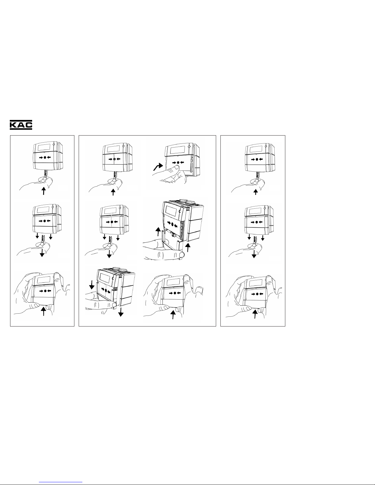
TO TEST TO REPLACE GLASS / RESETTABLE ELEMENT TO RESET
1
2
3
Important Notes; Please do not over tighten fixing screws.
The use of lubricants, cleaning solvents or petroleum based products should be avoided.
The O-ring should be replaced when refitting or replacing the Waterproof Cover.
KAC ALARM COMPANY LIMITED, KAC House, Thornhill Road, Redditch, Worcestershire, England. B98 9ND. T. +44 (0) 1527 406655 F. +44 (0) 1527 406677 E. technical@kac.co.uk W. www.kac.co.uk
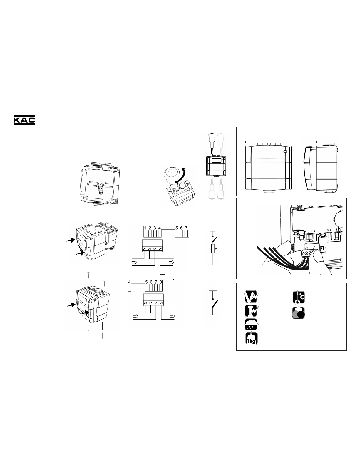
CONNECTION DETAILS
27.5mm
43mm
WCP1A-X
TECHNICAL DATA
-250C to +700C
Red, Ral 3001
Yellow, Ral 1006
Green, Ral 6024
White, Ral 9010
Blue, Ral 5005
PUSH FIT CONNECTOR
93mm
D900 issue 8
INSTALLATION INSTRUCTIONS FOR THE WATERPROOF MANUAL CALL POINT MODELS WCP1A....,
After wiring the
terminal connector,
plug into the
appropriate position,
see connection
details
(left).
OR
97.5mm
X in the WCP code (above) represents the final digits of the part number, which
indicate MCP colour, component values, mounting options and element type. eg
WCP1A -R470SF = (WCP1A, Red, 470R, Surface, Flexible Element).
DIMENSIONS
+
+
-
Model WCP1A
This Model provides a Normally Open contact with
series monitoring resistor or a clean, normally open
contact by means of the alternative positioning of the
terminal connector.
General
These Call Points are suitable for
IP67 environments.
Wall Mounting of Back Box
Mount the back box to a suitably
flat surface using the three fixing
holes and the screws provided in
the installation pack. The cable
entry holes should be in the
vertical plane. The back box can be mounted with
either the single or the double entry holes at the top.
Fitting the WCP Cover
to the back box
Plug the 4 way terminal
connector onto the
appropriate position as
shown. Ensure that the
O-ring is correctly seated
in the channel on the rear
of the cover. Place the
cover squarely over the
back box and carefully
push the cover until the
locating clips have
engaged. Do not use
excessive force. It is
recommended that the 4
cover fixing screws are
used to lock the cover
into place.
WCP Cover removal
To remove the cover, undo and
remove the 4 Cover fixing screws.
Place the edge of a large flat bladed
screwdriver into the slot between the
Cover and back box as shown in
below and gently twist until the
latches are
disengaged. Pull
cover away from
backbox.
-
30VDC Max
2A Max
IP 67
350g
1 2
3 4
7 8
5 6
We reserve the right to amend the content of this document without prior notice.
 Loading...