


User manual KB-ECOLINE series English
CH
Calorifier
Combi
Ecoline serie

Instruction manual Kabola KB-Series version 6, 2018
2
Preface
This user-manual is written to enable the safe operation of the central heating boilers with integrated tap
water supply ore boiler function. The user must read this manual before installation of the boiler and
must follow the instructions within this manual.
Therefore, this manual must be kept with the boiler.
In chapter 2, the safety instructions are detailed, which have to be complied with, when installing and
using the boiler. In other chapters you will find safety instructions, that can be identified in the following
way.
Hint: This gives the user suggestions and advises to facilitate the execution of
certain tasks.
Attention: Additional information is supplied to the user, and possible problems are
indicated.
Warning: Watch out for possible (life-threatening) injuries.
For any remarks, wishes or omissions you can contact Kabola Heating Systems. We also welcome
any remarks to improve this manual. We wish you a lot of pleasure from your purchase.
Kabola Heating Systems
Placotiweg 1E
NL 4131 NL Vianen
The Netherlands
Phone +31 (0)347-320030
Web: www.kabola.nl
E-mail info@kabola.nl
Vianen 2018
© 2018 Kabola Heating Systems
Copying of (parts of) this manual, is only allowed with written consent of Kabola Heating Systems.

Instruction manual Kabola KB-Series version 6, 2018
3
Table of contents
Preface 2
Table of contents 3
1 Introduction 4
1.1 General 4
1.2 Range of application 4
1.3 Product description 4
1.4 Technical specifications 4
2 Safety 5
2.1 General safety 5
2.2 Safety instructions 5
3 Transport and storage 6
3.1 Transport 6
3.2 Storage 6
4 Installing and preparing for first use 7
4.1 Installation 7
4.1.1 Fitting the boiler 7
4.1.2 Connection to the central heating system and domestic hot water 8
4.1.3 Flue gas outlet 9
4.1.4 Electrical connection 12
4.1.5 Filling the central heating system 14
4.1.6 Mounting the oil filter and oil burner. 15
4.2 Starting your system 15
5 Operating the boiler 16
5.1 Explanation of the dashboard 16
5.2 Operating the tap water on/off button 18
6 Cleaning and maintenance 19
6.1 Points for attention 19
6.2 Cleaning and maintenance 19
7 End of life of the boiler 19
Appendix A Technical specifications 20
Appendix B Electrical diagram 230 V 21
Appendix C Troubleshooting 23
Appendix D Boiler parts 24
Appendix E EG-declaration 29
Appendix F CE declaration 30
Appendix G Guarantee conditions 32

Instruction manual Kabola KB-Series version 6, 2018
4
1 Introduction
1.1 General
Congratulations with your purchase of this Kabola boiler. This user-manual covers all kind of boilers in
the KB-series. The KB- boilers cover a wide range of boilers with a broad range of applications. By
purchasing this boiler, you have acquired a product, which is of high quality through the application of
the latest European standards and directives.
1.2 Range of application
The Kabola KB-Series are designed to generate heat for the heating of water and for a central heating
system. The boilers can also be used for the generation of domestic hot water generated by a compact
brazed heat exchanger. The dimensions of the rooms to be heated, have to be taken into consideration.
These boilers are not designed for direct heating of the rooms in which they are installed.
1.3 Product description
The boilers of the KB- series heats the boiler water by means of a pressure jet burner which is installed
at the front of the boiler. The boilers are available in both 230 VAC version. For fuel, diesel oil has to be
used.
1.4 Technical specifications
The most important technical specifications are listed on the plate at the back of the boiler. More
technical details are listed in Appendix A.

Instruction manual Kabola KB-Series version 6, 2018
5
2 Safety
In this chapter we emphasis the safety-related points for operating the boiler.
2.1 General safety
Warning: Although Kabola Heating Systems designs and produces its products
according to the current safety standards, it is possible that dangers may
present themselves, which could lead to injuries or damage to the boiler, if the
safety instructions in this manual are not complied with.
The user must:
Have read and understood the chapter "safety";
Avoid any actions which may lead to dangers to his health or others;
Avoid any actions which may lead to damage to the boiler;
Ensure that the boiler is only used when the boiler is in sound technical condition;
Ensure that the safety regulations are observed whilst operating the boiler.
Attention: No alterations to the boilers may be done, without the explicit written consent
of Kabola Heating Systems!
2.2 Safety instructions
In this chapter we emphasis the safety-related points for operating the boiler.
MEASURES FOR A SAFE INSTALLATION
Don't store any flammable and/or gaseous products in the room where the boiler is installed to avoid
explosions and fires.
Install the boiler in a non-humid environment on a firm horizontal base.
Ensure that there is sufficient ventilation in the room where the boiler is installed (See also § 4.1.1).
Make sure, before you start connecting the boiler, that the system is disconnected from the power
supply.
Only use multi-stranded wire for electrical connections.
MEASURES FOR A SAFE OPERATION
Never change the settings of the burner.
Don't use any aggressive solvents which may affect the boiler (like petrol or turpentine).
Insulate the chimney, when it can be touched by body parts.
Make sure that the boiler and burner are checked annually by a skilled expert.
Make sure that before you start any work on the boiler that the system is disconnected from the
power supply.
Make sure that any surplus oil is collected in case of oil spillage.
We advise you to have any maintenance or repairs carried out by skilled experts.

Instruction manual Kabola KB-Series version 6, 2018
6
3 Transport and storage
Figure 1
3.1 Transport
Take following precautions before transporting the
boiler:
Drain the water from the boiler;
Uncouple the fuel system;
While transporting the boiler take following precautions:
Don't damage the boiler, use a blanket to cover the
boiler;
Transport the boiler standing up.
3.2 Storage
Take the following precautions when the boiler is
stored for a longer period of time:
Store the boiler and accompanying parts in a dry
place;
Store the boiler standing up;
Store the boiler on a firm horizontal base.

Instruction manual Kabola KB-Series version 6, 2018
7
4 Installing and preparing for first use
In this chapter you will find directions and hints for a correct placement and fitting of the boiler and
accompanying parts.
Warning: Do not store any flammable or gaseous substances in the room where the
boiler installed. This is to ensure that no explosions or fires can occur.
4.1 Installation
4.1.1 Fitting the boiler
Install the boiler in a dry place.
Install the boiler on a firm horizontal base.
Make sure there is sufficient supply of fresh air in the room where the boiler is installed (see hint
below).
To avoid movement secure the base of the boiler by using the holes with M5 threat in the feet from
the boiler (figure 1)
Keep a minimum distance of 250 mm behind the boiler for the flue-gas outlet
Use an earthed plug socket for connecting the 230 Volt AC versions to the power supply.
Hint: As a rule of thumb for the ventilation openings, take 2,5 times the diameter
of the flue gas outlet.
Instruction manual Kabola KB-Series version 6, 2018
8
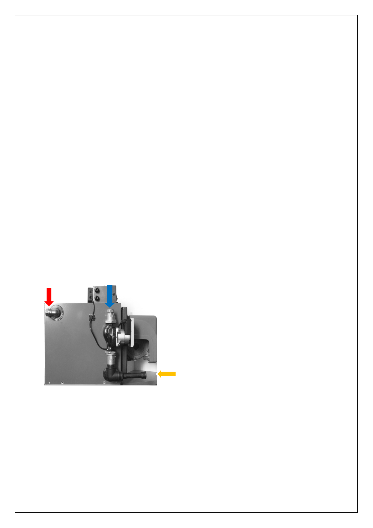
4.1.2 Connection to the KB central heating system
4
2
1
PIPING
Take note of the following points, when installing the piping:
Install the piping in such a way, that the boiler (cover and dashboard) remains accessible;
Provide enough bleeding points in places where air may collect, especially near the boiler.
Attention: Install a bleeding point near the boiler, especially when the piping does not
go up.
Installation KB - CH:
Connect the piping to the boiler as follows (see figure 2 –2.2):
1. Install the feed of the boiler on nr 1
2. Install the return of the boiler on nr 2
3. Install the fill and pressure gauge on nr 4
Hint: Because the water pressure in the domestic water system is not always
stabile, we recommend to use thermostatic controlled water cranes.
It is possible to use the boiler when the domestic water side is not connected
KB-20 / 40 / 45 / 50 / 75

Instruction manual Kabola KB-Series version 6, 2018
9
Installation KB boiler with Calorifiercontrol:
2
4
1
3
B
A
Figure 2.3
1. Install the feed of the Calorifier on nr 1 / B
2. Install the return of the boiler and Calorifier on nr 2
3. Install the feed of the boiler on 3 / A
4. Install the fill and pressure gauge on nr 4
5. The numbers A and B you will find on the housing of the three-way valve
Note: There must always be a thermostat mounted on the Calorifier to
communicate with the KB series (available at your Kabola supplier with number: 9-i025)

Instruction manual Kabola KB-Series version 6, 2018
10
Installation KB –Combi:
1
2
5
6
Figure 2.4
1. Install the feed of the boiler on nr 1
2. Install the return of the boiler on nr 2
3. Install the fill and pressure gauge on nr 4 (see figure 2.3)
4. Install the output (hot water) of the combi on nr 5
5. Install the input (cold water) of the combi on nr 6
4.1.3 Flue gas outlet
GENERAL
The flue gas outlet is an essential part of your heating installation. An incorrect flue gas outlet reduces
the lifespan of your boiler considerably and has a negative impact on the efficiency. Remember when
installing the flue, that even the best boiler won't work properly unless the flue is properly installed.
Warning: Because the flue gas temperature lies between 150-200°C, it is advisable to
insulate the flue with heat-resistant material on those parts where contact with
human body parts is possible.
For a correct flue gas outlet the following points need to be observed:
Use the proper diameter, use a diameter equal to the diameter of the flue gas outlet on the boiler
(see also technical specification).
Use double-walled chimney pipe outside to prevent a rapid cooling of the exhaust gasses, which
may result in condensation in the chimney.
Hint: When using an existing chimney of a larger diameter than the diameter on the
boiler, you can install flexible piping of the correct diameter insides the
existing chimney.
Warning It is necessary that condensation water always can flow back to the drain of the
boiler, avoid water bags!! The boiler has got a high efficiency, and the burner will
start even when there is no heat demand, this is done to avoid that there is a lot
of condensation in the boiler. Condensation will short the life time of the boiler
Instruction manual Kabola KB-Series version 6, 2018
11
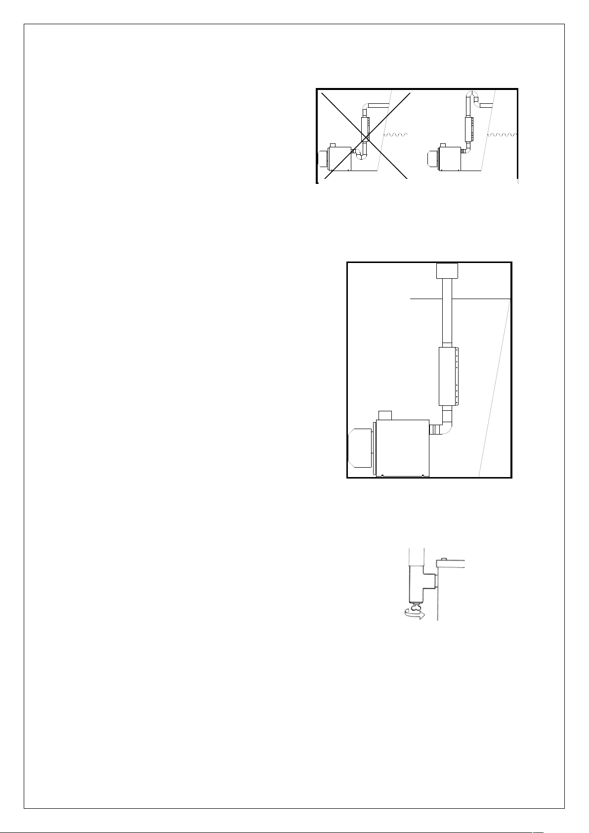
Figure 3
Figure 4
HORIZONTAL FLUE GAS OUTLET
Always install a drain with tap directly on the boiler
See Figure 4.a
It is possible to fit a horizontal flue gas outlet to the
boiler. The following points need to be observed:
Make sure that the outlet is positioned at a sufficient
height above the waterline. If this is not possible use
a swan neck bend in the pipe as in figure 3.
Use the correct hull fittings for installing the flue
through a hull side
The maximum allowed length, without curves is 10
meters. At more than 10 meters in length, always contact Kabola for advice.
Don’t use more than 4 elbows of 90°.
Every elbow of 90° is equivalent to 1 meter straight pipe
VERTICAL FLUE GAS OUTLET
This way if installation is preferable for seagoing boats and
sailing boats, because these boats encounter large angles of
heel through waves and under sail. For this kind of flue gas
outlet, the following points are important:
Install a proper storm cowl on top of the chimney (this must
stop rain from entering) (figure 4).
Install deck fittings for installing the flue through a deck.
Install a water trap, to drain possible water caused by
condensation
Keep the chimney as vertical as possible.
Don't use more than 4 elbows 90°.
The maximum allowed length is 10 meters. At more than
10 meters in length, always contact Kabola for advice.
Every elbow of 90° is equivalent to 1 meter straight pipe.
Use outside double walled chimney pipe
Hint: To reduce the noise from flames, it
is wise to install a silencer in the
exhaust.
Figure 4.a
Your Kabola supplier can provide you with all components which may be required for installation such
as:
Cowls;
Flexible piping;
Single and double walled chimney pipes;
Hull and deck fittings;

Instruction manual Kabola KB-Series version 6, 2018
12
Silencers;
Lx L1
Figure 6.2
Water traps;
Insulation.
Be aware that the 3-way valve only opens to the central heating system when the
temperature in the boiler is above the 50 Celsius degrees, this is to avoid that there is
condensation in the boiler.
4.1.4 Electrical connection
Warning: Disconnect the power supply from the boiler before you start the installation.
The quality of 230 VAC power supply to the boiler should be as good as
the power supply from a land line.
To connect the room thermostat for KB-Standard:
Remove the cover of the thermostat
Connect the two thermostat wires to point Lx and L1 (figure 6.2)
Remove the cover from the connector that is located on the left backside of the dashboard
(green arrow).
Remove the bridge from T1 and T2 and connect the 2-core cable of the room thermostat to T1
and T2, as indicated on the sticker in the connector.

Instruction manual Kabola KB-Series version 6, 2018
13
To connect the room thermostat for KB- Combi – Calorifier:
Q14 Q11 Q21 Q22
↓ ↓ ↓ ↓
T1 T2 S3 B4
Figure 6.1
Figure 6
Right plug Fig. 12
Figure 11
Before you connect the room thermostat with Frost Guard, use a 4-core insulated wire 0,75
mm2.
Remove the right plug (green arrow) which you can find at the backside of the Kabola
dashboard (figure 12).
Connect the 4 wires of the room thermostat at T1 and T2 and S3 and B4 in connection A
(figure 11) at the backside of the dashboard as shown on the sticker inside the connector.
Connect the wires inside the room thermostat (Fig. 6.1) to Q14 (T1) and Q11 (T2)
Connect the Frost Guard connections (Fig 6.1) of the room thermostat to connections Q21
(S3) and Q22 ( B4) and in the plug on S3 and B4 (figure 11) at the back of the dashboard.
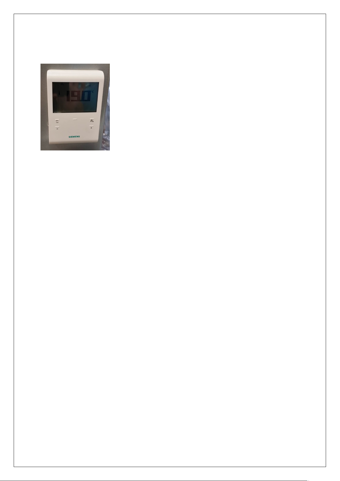
If the room thermostat shows a tap on its display the tap water is switched on, if there’s no tap
visible on the display, tap water is switched off.

Instruction manual Kabola KB-Series version 6, 2018
14
Figure 7
4.1.5 Filling the central heating system
The pressure in the system should:
Never be lower than 0,5 bar cold;
Never be higher than 2,5 bar hot.
Follow the procedure below for filling the CH-system (see figure
7):
Switch off the boiler;
Remove nob 4
Screw the adaptor 3 at the thread,
Connect the filling tube at 3 and open 5 by turning it;
Fill the system slowly with water, until the pressure indicator
indicates a pressure of 2 bar;
Close the valve (2);
Bleed the CH-system;
If necessary, fill with water again up to 2 bar of pressure;
Switch on the boiler and let the pump run for about 5
minutes;
Switch off the boiler;
Check the water pressure, if it is too low, repeat steps 5 through 10;
Remove the hose.
Hint: The CH-system can be filled with cooling fluid, suited for CH-systems (pH-
value 8.5)
Bleeding the circulation pump
Adjust the temperature of the room thermostat higher than the ambient temperature (for
example, 5 degrees higher);
Set the on / off switch (button lights);
Put the heating pump in automatic venting position. Control knob to 12 hours (see Figure 9);
Turn a quarter of a turn the red button after about 5 minutes, to position 3 (see Figure 10);
Check the entire system for air and check the pressure (fill if necessary).
Tip: If you do not live permanently on board we recommend to fill the heating system with coolant.
The cooling liquid must be suitable for heating systems (pH value 8.5). For more information please
contact your dealer or Kabola, Netherlands
See manual from the circulation pump.
Attention: When locking pump couplings are supplied with the boiler, the adjusting
grooves must point towards the pump.
Venting mode: Turn switch on 12 o’clock Operating mode: Turn switch at +/-position 3
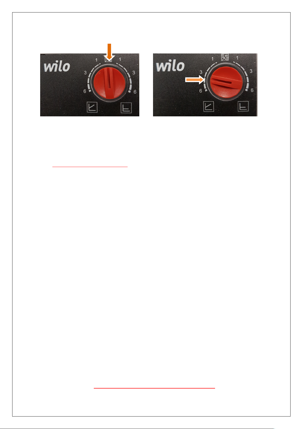
Instruction manual Kabola KB-Series version 6, 2018
15
(light flashes) (the light will burn continuous)
Figure 8
4.1.6 Mounting the oil filter and oil burner.
The KB-series will be standard supplied with a self-bleeding oil filter, what is SI approved, this oil filter
should always be hung above the burner, if this filter is not above the level from the oil pump it will not
work correctly!
The oil burner is already mounted on the boiler, the flexible oil hoses, what are fitted on the burner,
needs to be connected to the oil filter, those two flexible oil tubes, an inlet, and a return line. Place
these lines on the filter. On the filter are arrows!
Use the oil line from the fuel oil pipe stainless steel with an inner diameter of 6-8 mm.
For further instructions from the oil burner, refer to the instructions of the burner.
4.2 Starting your system
After the room thermostat is connected, the following steps:
1. Insert the plug into the grounded socket for 230 volt version.
2. Switch the boiler on, at the on / off switch on the control panel. The lamp in the switch indicate
that the system is on.
3. Set the room thermostat. (see manual of the room thermostat)
4. Open the valve on the fuel tank;
5. Open the valve on the oil filter;
6. Disconnect the power from the motor to the oil burner (only Kabola engineer)
7. Use the startup cable, and connect with this cable the power to the motor from the oil pump
8. Assemble the pump pressure gauge at plug P from the oil pump
9. Check if the system is bleeded and check the right oil pressure
10. Start the burner;
11. After ± 2 minutes, the burner will start
12. Check all oil connections for leaks;
13. If the burner does not start, the fault light is on;
14. Wait about 3 minutes;
15. Reset the burner and go to 5.4 (repeat if necessary).
Attention: The oil burner is tested by the manufacturer, not adjusted. The adjustment of
the burner has to be done by an experienced installer, because this
requires expert knowledge. To be eligible for warranty, the boiler has to be
adjusted by an approved installer. Contact your Kabola supplier to make an
appointment.
Never adjust the burner using your own initiative!!

Instruction manual Kabola KB-Series version 6, 2018
16
5 Operating the boiler
Numbers
Explanation
Photo
0
Rest position (boiler is on stand-by)
Circulation pump stopped
1
Room thermostat demands heat.
Circulation pump operating
3
Circulation pump further running time.
Circulation pump operates for ± 3
minutes
When the boiler has been started and adjusted according to 4.2, operation for the boiler is very simple.
The required temperature is set with the room thermostat, which controls the boiler. The boiler
thermostat controls the 3-way valve on the boiler. The operation of the room thermostat is explained in
the manual of the room thermostat.
If problems arise with the operation of the boiler, you will find a list of possible problems and solutions
in Appendix C.
5.1 Explanation of the dashboard
KB-series Boiler
Display
On/off switch Boiler thermostat
Explanation of the operating panel
Set the required boiler temperature at 80 °C (Boiler thermostat: press knob and turn).
KB-series Combi-Calorifier

Instruction manual Kabola KB-Series version 6, 2018
17
Dashboard front of the KB-series
0
Rest (boiler is stand-by)
Circulationpump not active
1
Room thermostat is demanding
Circulation pump active
2
Hot water is being tapped or external boiler requires
heat.
Circulation pump active
3
Pumptimer active
Circulation pump running ± 3 minutes
4
Boiler is heating to keep domestic water on
temperature.
Blinking dot = Hot water out
Burning dot = Hot water stand-by
The number (19) on the right side of the display shows
the current boiler water temperature
Display
On / Off switch Figure 9 Boiler thermostat
Set the required boiler temperature at 80 °C (Boiler thermostat: press knob and turn).
Instruction manual Kabola KB-Series version 6, 2018
18
5.2 Operating the tap water on/off button
By pushing the tap-button on the room thermostat tap water can be switched on and off. If the display
shows the tap, than tap water is switched on. If the display doesn’t show a tap, than the tap water is
switched off.
To switch on the Frost Guard, you’ll have to proceed the following steps:
1. Switch off the tap water. There shouldn’t be a tap visible on the display of the room thermostat.
2. At the Kabola dashboard you’ll see a flashing dot.
If you just want to use tap water and no heating, you’ll have to proceed the following steps:
1. If the tap is visible at the display of the room thermostat, than the tap water is switched on. If not, it’s
switched off. Please switch on.
2. The display on the Kabola dashboard won’t show the flashing dot anymore, if correct.
3. Put the room thermostat on a low temperature.
If you want to use both tap water and central heating, please follow the next steps:
1. If the tap is visible on the display of the room thermostat, the tap water is switched on
2. On the display of the Kabola dashboard, the dot won’t flash anymore
3. Make sure the temperature on the room thermostat is set for demand (if you want to test: put it
higher than the current temperature).

Instruction manual Kabola KB-Series version 6, 2018
19
6 Cleaning and maintenance
6.1 Points for attention
Spare parts must be ordered through your Kabola supplier. For warranty purposes only original spare
parts must be used. When ordering spare parts, state the type of boiler and its serial number. Your
Kabola supplier will then be able to supply the correct parts. In Appendix B, the main spare parts are
listed.
6.2 Cleaning and maintenance
Warning: Maintenance and repairs should only take place when the boiler is switched
off, this is because the boiler may start unexpectedly. Take the plug form the
wall socket for the 230 VAC versions.
Warning: Maintenance and repairs may only be performed by personnel, who have read
and understood the information in this manual, preferably an expert installer
or a service engineer from Kabola Heating Systems.
Every year
1. Clean the boiler
1.1. Remove the burner with the door from the boiler;
1.2. Remove the insulation.
1.3. Clean the inside of the boiler, using a stiff brush;
Attention: Don’t use any aggressive solvents like thinner or gasoline.
1.4. Clean the boiler with a vacuum cleaner;
1.5. Replace the isolation;
1.6. Replace the door with burner;
2. Clean the chimney;
3. Change the oil filter element;
4. Clean the burner (see manual of the burner)
Attention: The old oil filter element has to be processed as chemical waste.
7 End of life of the boiler
When the boiler is scrapped, take note of the points listed below:
Process the oil filter and the oil hose as chemical waste;
Separate the metal from the plastic parts and dispose of them separately.
Process any excess oil in an environmentally friendly way.
Transport the boiler according to the instructions in chapter 3
Recycle this manual.

Instruction manual Kabola KB-Series version 6, 2018
20
Appendix A: Technical specifications

Instruction manual Kabola KB-Series version 6, 2018
21
Appendix B Electrical diagram 230 V

Instruction manual Kabola KB-Series version 6, 2018
22
Appendix B Electrical diagram 230 V

Instruction manual Kabola KB-Series version 6, 2018
23
Appendix C Troubleshooting
Problem
Possible reason
Possible solution
Burner will not start
Oil supply interrupted
Maximal thermostat
Bleed the oil filter
Change contaminated filter element
Fill the oil tank
Reset the maximal thermostat
Power supply interrupted
Check the fuses (4-8A)
Check the power supply
Shut down power supply, and
disconnect the photo cell, switch
power on and when burner starts
connect the photo cell.
Burner stops
Reset burner (once)
Flame protection dirty (photo cell)
Clean glass of flame protection
Flame protection defect
(photo cell)
Replace flame protection
Burner starts pulsing
Flue gas flow interrupted
Clear chimney opening
Boiler dirty
Clean boiler
Oil supply interrupted
See above
Nozzle defective
Replace nozzle
Burner shows error
Reset burner (once)
Low voltage
Check voltage level
Press the reset button for more
than 3 seconds
2 blinks, alarm on terminal 10
No establishment of flame at the
end of safety time
Faulty or soiled fuel valves
Faulty or soiled flame detector
Poor adjustment of burner, no fuel
Faulty ignition equipment
3x blinks, alarm on terminal 10
Free
4 blinks, alarm on terminal 10
Extraneous light on burner startup
5 blinks, alarm on terminal 10
Free
6 blinks, alarm on terminal 10
Free
7 blinks, alarm on terminal 10
Too many losses of flame during
operation (limitation of repetitions)
Faulty or soiled fuel valves
Faulty or soiled flame detector
Poor adjustment od burner
8 x blinks, alarm on terminal 10
Time supervision oil preheater
Oil preheater failed 5 times during
prepurging
9 blinks, alarm on terminal 10
Free
10 blinks
Wiring error or internal error, output
contacts, other fault
Press the lockout reset button for
about 1-3 sec to reset burner
Oil supply interrupted
See above
Boiler does not react to thermostat
Wire in main connector has not
been removed (room thermostat)
Remove wire from main connector
between T1 and T2
Boiler thermostat incorrectly
adjusted
Adjust boiler thermostat
Battery of room thermostat flat
Replace battery
Water is not circulating
Pump couplings are closed
Open pump couplings
Pump not connected to electricity
supply
Connect pump
Rotor of pump is stuck
Turn pump with your hand (see
pump manual)
Listed below you will find a list with possible problems, their reasons and solutions. When you encounter
problems not listed, you should contact your dealer. Never try to solve problems on your own.
When problems with the boiler will not disappear, call an engineer from Kabola.

Instruction manual Kabola KB-Series version 6, 2018
24
Appendix D Boiler parts model 2012 - 2016

Instruction manual Kabola KB-Series version 6, 2018
25
Appendix D Boiler parts model 10-2016- 2017
Spareparts list model 2012 - 2016

Instruction manual Kabola KB-Series version 6, 2018
26
Pos
Description
Article number
1Boiler housing
2
Dashboard KB-series 230V
51-001
3
Stainless steel efficiency tube only KB20
44-005
4
Insulation boiler KB40 300 x 300 x 20 mm
46-005
4
Insulation boiler KB45/KB50 327 x 299 x 20 mm
47-005
4
Insulation boiler KB75 420 x 360 x 20 mm
49-005
5
Door gasket
9-I083
6
Insulation door KB40 282 x 282 x 15 mm
46-004
6
Insulation door KB45-KB50 310 x 282 x 15 mm
47-004
6
Insulation door KB75 404 x 342 x 15 mm
49-004
7
Door-8
Bolt M10-9
On request
-
10
Burner plate
-
11
Burner Block Module
52-001
12
Ring adapter for burner module
52-002
13
Adapter tube 80 x 1.5 x 109 mm
52-003
14
Burner tube KB-serie
52-004
15
Seal for KB-burner
52-005
16
Door bolt with shim
52-006
17
Feed burner control LOA24
52-007
18
Burner connector 7 pole KB-series
52-008
19
Burner controlt LOA24
52-009
20
Motor 70 watt
52-010
21
Bearing plate for oil pump motor
52-011
22
Oilpump coupling KB-series
52-012
23
Scheer oil pump KB-series
52-013
24
Oilhose KB-series
52-014
25
Blower fan RG148 KB-series
52-015
26
Seal adapter tule
52-016
27
Seal for nozzle stem retaining plate
52-017
28
Nozzle KB40
52-019
28
Nozzle KB50
52-046
28
Nozzle KB45
52-020
28
Nozzle KB75
52-021
29
Dosage ring KB-series
52-022
30
Mixing cartridge complete KB40
52-024
30
Mixing cartridge complete KB45
52-025
30
Mixing cartridge complete KB50
52-025
30
Mixing cartridge complete KB75
52-026
31
Nozzle holder complete KB40
52-027
31
Nozzle holder complete KB45-KB50
52-028
31
Nozzle holder complete KB75
52-029
32
Electrode KB40-KB45
52-030
32
Electrode KB50-KB75
52-031
33
Flame detector KLC2002
52-032
34
Mounting plates for number. 35, 36 en 37
-
35
Ignition transformator
52-033
Instruction manual Kabola KB-Series version 6, 2018
27
Pos
Description
Article number
36
After purge relais
52-034
37
Control board for fan speed KB40
52-036
37
Control board for fan speed KB45
52-037
37
Control board for fan speed KB75
52-038
38
Pressure sensor KB-series
52-039
39
Condensator KB-series
-
40
Circulation pump 230V 130 high
9-I053
41/42/43/49
Locking pump coupling set Kabola
24-x063
44
Knee type221 1”
18-S482
45
Conversion ring 1” bui x ½” bin
18-S297
46
Pipe nipple ½” x 120 mm
18-S483
47-48
Fill and pressure gauge
9-I015
50
Tap casing
-
51
Back of tap casing
-
52
Heat exchanger
24-x091
53
Viber ring
-
54
¾”Flexible hose 22 mm
51-003
55
Bras Knee ½”ins. X ½” out.
51-004
56
T-connection 22 x 22 x 22 mm
17-R080
57
Knee coupling 1”out x 22 mm
17-R125
58
Ball valve ½”out x ½”out
51-005
59
Prefer switch
9-I018
60
Knee coupling 1” out x 22 mm
17-R125
61
3-way valve 24 VAC (v8044c1065)
10-J004
62
Coupling 1 “out x 22 mm
17-R149
63
Coupling ½” ins. x 15 mm
17-R157
64
Knee coupling ½” x 15 mm
17-R068

Instruction manual Kabola KB-Series version 6, 2018
28
Spareparts list model 2016- 2017

Instruction manual Kabola KB-Series version 6, 2018
29
Appendix E EG-declaration
EG-declaration of conformity
We,
Kabola Heating Systems BV
Placotiweg 1 E
4131
NL
Vianen
The Netherlands
decIare under our own responsibility that the product:
Kabola KB20/KB40/ KB45/ KB50/ KB75 combi 230V
to which this declaration relates complies with the fol/owing standards
EN 303-1, EN 303-2, EN 304, EN 50081-1, EN 50082-1. EN 61010
fol/owing the provisions of the fol/owing EC-directives
73/23/EEG,
89/336/EEG,
92/42/EEG,
amended by 93/68/EEG.
Nederland, Vianen, 18th februari 2015
Arie van Soolingen
Managing Director
Instruction manual Kabola KB-Series version 6, 2018
30
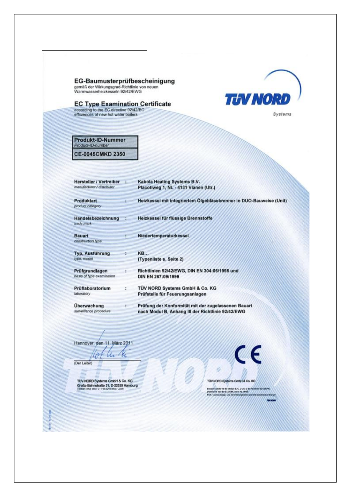
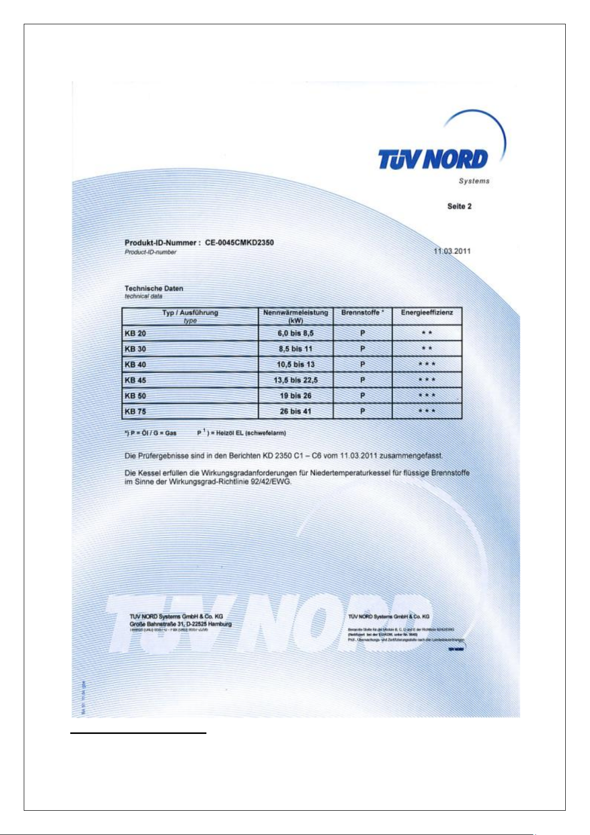
Appendix F CE declaration
Instruction manual Kabola KB-Series version 6, 2018
31
Warranty Conditions

Instruction manual Kabola KB-Series version 6, 2018
32
Appendix G Guarantee conditions
 Loading...