


SIMPLEX
®
EE1000 Series
English
Pushbutton Lock Installation Instructions
Español
Cerradura de Botones Pulsadores Instrucciones de Instalación
Français
Serrure à Button-Poussoirs Instructions d'installation

2
ETAPA PÁGINA
1 Marcado de la puerta . . . . . . . . . . . . 6
2 Perforación de los agujeros . . . . . . . 6
3 Instalación del pestillo . . . . . . . . . . . . 8
4 Ajuste de la cerradura para puertas
de 1
1
⁄
2
"
pulgada (38 mm.) . . . . . . . . 10
5 Ajuste de la cerradura para puertas
de 2 pulgadas (51 mm.) . . . . . . . . . 12
6 Cambio de la dirección de
apertura de la cerradura . . . . . . . . . 14
7 Alineación de la cerradura
exterior. . . . . . . . . . . . . . . . . . . . . . . 16
8 Prueba de la cerradura exterior . . . 16
9 Instalación de la cerradura
exterior. . . . . . . . . . . . . . . . . . . . . . . 18
10 Instalación de la cerradura
interior . . . . . . . . . . . . . . . . . . . . . . . 18
11 Prueba de la cerradura interior . . . . 20
12 Instalación del cerradero. . . . . . . . . 22
13 Cambio de la combinación . . . . . . . 24
14 Mantenimiento del pestillo. . . . . . . . 26
15 Registro de combinaciones. . . . . . . 28
16 Anulación de una
combinación perdida . . . . . . . . . . . . 30
17 Localización y reparación
de averías . . . . . . . . . . . . . . . . . . . . 34
Plantilla . . . . . . . . . Centro del manual
Tarjeta de garantía Centro del manual
#$! !
1 Marking the door . . . . . . . . . . . . . . . . 6
2 Drilling the holes . . . . . . . . . . . . . . . . 6
3 Installing the latch . . . . . . . . . . . . . . . 8
4 Adjusting the lock for doors
1
1
⁄2" (38 mm) thick . . . . . . . . . . . . . . 10
5 Adjusting the lock for doors
2" (51 mm) thick . . . . . . . . . . . . . . . 12
6 Changing the hand of the lock . . . . 14
7 Aligning the outside lock . . . . . . . . . 16
8 Testing the operation of the
outside lock . . . . . . . . . . . . . . . . . . . 16
9 Installing the outside lock . . . . . . . . 18
10 Installing the inside lock . . . . . . . . . 18
11 Testing the operation of the
inside lock . . . . . . . . . . . . . . . . . . . . 20
12 Installing the strike. . . . . . . . . . . . . . 22
13 Changing the combination . . . . . . . 24
14 Preserving the latch. . . . . . . . . . . . . 26
15 Combination setting record . . . . . . . 28
16 Clearing a lost combination. . . . . . . 30
17 Troubleshooting. . . . . . . . . . . . . . . . 34
Template. . . . . . . . . . . . center of book
Warranty card. . . . . . . . center of book
English
Table of Contents
Español
Indice
Please read and follow all
directions carefully
Since correct installation is critical,
carefully check windows, frame, door, etc.
to make sure that the recommended
procedures will not cause any damage.
KABA is not responsible for any damage
caused by installation.
Lea y siga cuidadosamente
todas las instrucciones
Dado que es muy importante instalar correctamente la cerradura, verifique meticulosamente
las ventanas, el marco, la puerta, etcétera, para
asegurarse de que el procedimiento de instalación recomendado no provocará ningún desperfecto.
KABA no se hace responsable de ningún deterioro causado por la instalación.

3
@$! !
1 Marquage de la porte . . . . . . . . . . . . 7
2 Perçage des trous. . . . . . . . . . . . . . . 7
3 Installation du pêne . . . . . . . . . . . . . . 9
4 Ajustement de la serrure pour portes
de 1
1
⁄2" (38 mm) d'épaisseur . . . . . . 11
5 Ajustement de la serrure pour portes
de 2" (51 mm) d'épaisseur . . . . . . . 13
6 Changement de la main de serrure 15
7 Alignement de la serrure extérieure 17
8 Vérification du fonctionnement
de la serrure extérieure. . . . . . . . . . 17
9 Installation de la serrure extérieure. 19
10 Installation de la serrure intérieure . 19
11 Vérification du fonctionnement de la
serrure intérieure . . . . . . . . . . . . . . . 21
12 Installation de la gâche . . . . . . . . . . 23
13 Changement de la combinaison . . . 25
14 Alignement entre la porte et
le jambage . . . . . . . . . . . . . . . . . . . . 27
15 Registre des combinaisons. . . . . . . 29
16 Annulation d'une combinaison
inconnue . . . . . . . . . . . . . . . . . . . . . 31
17 Dépannage . . . . . . . . . . . . . . . . . . . 35
Gabarit . . . . . . . . . . au centre du livret
Fiche de garantie . . au centre du livret
Français
Table des matières
For your records
Model #: ______________________
Date Purchased: ________________
Dealer: ________________________
Name: ________________________
Telephone: ____________________
Para su archivo
Modelo no : ____________________
Fecha de compra : ______________
Distribuidor : ____________________
Nombre : ______________________
Teléfono: ______________________
Pour vos dossiers
No de modèle : ________________
Date d'achat : __________________
Fournisseur : __________________
Nom : ________________________
Téléphone : ____________________
Veuillez lire et suivre
attentivement les
instructions
S’assurer que l'installation de la
serrure ne causera aucun dommage à
la fenêtre, au jambage ou à la porte.
KABA décline toute responsabilité pour
tout dommage résultant de l'installation.

4
Lista de verificación
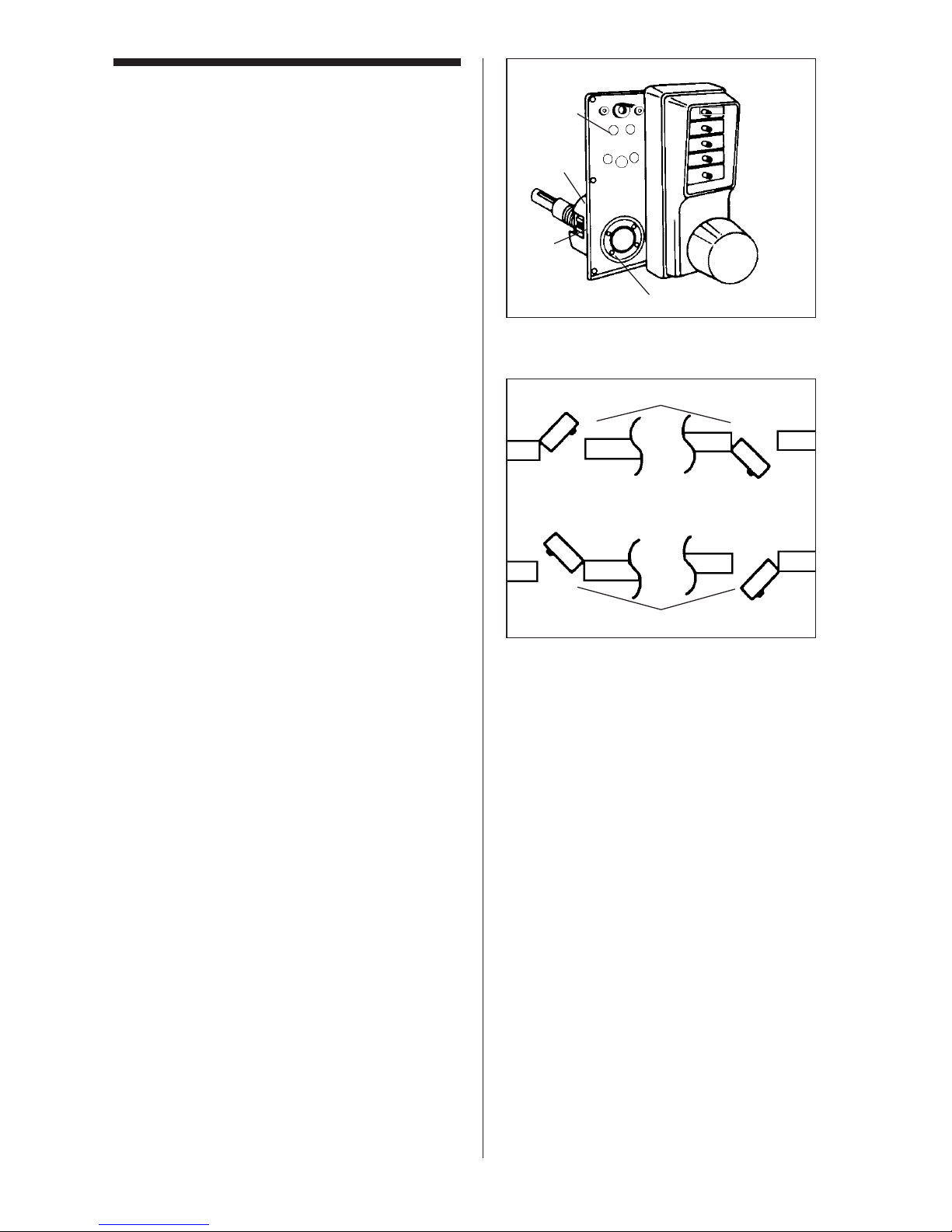
').#+8/+925)19+:/4)2;*+9
o A) Outside lock housing assembly
o B) Inside lock housing assembly
o C) Latch
o Screw/accessory pack:
a) strike box
b) strike plate
c) #10 size insert bit for “D”
d) anti tamper spanner screws
e) extra spacer,
1
⁄4" (6 mm)
f) torx anti-tamper screw
g) torx bit for “F”
h) four 8-32 x
3
⁄4" (19 mm) Phillips
combination screws (for latch
& strike)
i) four 8-32 x
11
⁄16" (17 mm) Phillips
sems screws (for spacer)
j) four 8-32 x
3
⁄16" (5 mm) Phillips
sems screws (for spacer)
k) pick for combination change
l) rubber bumpers
m) angle bracket
n) extra cross pins
o) two Phillips break-off screws
(for mounting outside lock and
angle bracket “M”)
o Warranty card
The template is included in the middle of
this booklet.
$55298+7;/8+*
o Electric drill (variable speed)
o Awl or center punch
o 2
1
⁄8" (54 mm) Hole saw with pilot drill
o 1" (25 mm) Hole saw with pilot drill
o
1
⁄4" ( 6 mm) Drill bit
o
1
⁄2" ( 12 mm) Drill bit
o 1" (25 mm) Wood chisel
o Hammer
o Phillips head screwdriver
o Small flat blade screwdriver
o Pliers (2)
Cada cerradura de la serie EE1000 incluye:
o A) Caja exterior de la cerradura
o B) Caja interior de la cerradura
o C) Pestillo
o Juego de tornillos / accesorios:
a) Caja del cerradero
b) Placa del cerradero
c) Broca de inserción para “D”,
tamaño 10
d) Tornillos inviolables para llave
de tuercas
e) Espaciador adicional,
1
⁄4" (6 mm)
f) Tornillos Torx inviolables
g) Broca Torx para “F”
h) 4 tornillos Phillips, 8-32 x
3
⁄4"
(19 mm) para la combinación
(para pestillo y cerradero)
i) 4 tornillos Phillips con arandela
premontada, 8-32 x
11
⁄
1
6
" (17 mm)
para espaciador
j) 4 tornillos Phillips con arandela
premontada, 8-32 x
3
⁄16" (5 mm)
para espaciador
k) Ganzúa para cambiar la
combinación
l) Topes de caucho
m) Soporte en escuadra
n) Pasadores transversales
suplementarios
o) 2 tornillos largos Phillips (para
montar la cerradura exterior y el
soporte en escuadra “M”)
o Tarjeta de garantía
Plantilla (en el centro del folleto)
Herramientas necesarias:
o Taladro eléctrico (de velocidad
variable)
o Punzón o punzón centrador
o Sierra de perforación 2
1
⁄8" (54 mm)
con broca guía
o Sierra de perforación 1" (25 mm)
con broca guía
o Broca
1
⁄4" (6 mm)
o Broca
1
⁄2" (12 mm)
o Formón para madera 1" (25 mm)
o Martillo
o Destornillador para tornillo Phillips
o
Destornillador pequeño de cabeza
plana
o 2 alicates
Checklist

5
.'7;+9+88;8+*+2'9B8/+
)5368+4*2+96/C)+99;/<'4:+9
o A) Serrure extérieure
o B) Serrure intérieure
o C) Pêne
o Jeu de vis et d'accessoires:
a) boîtier de gâche
b) gâche
c) outil rapporté n°10 pour accessoire D
d) vis à tête d’écrou inviolables
e) entretoise supplémentaire,
1
⁄4" (6 mm)
f) vis Torx inviolables
g) outil rapporté pour accessoire F
h) 4 vis à tête combinée Phillips 8-32 x
3
⁄4" (19 mm) pour pêne et gâche
i) 4 vis sem Phillips 8-32 x
11
⁄16"
(17 mm) pour entretoise
j) 4 vis sem Phillips 8-32 x
3
⁄16"
(5 mm) pour entretoise
k) crochet pour vis antivol du cylindre
de changement de combinaison
l) butées de caoutchouc
m) équerre de fixation
n) contre-goupilles supplémentaires
o) 2 vis cassables Phillips pour serrure
extérieure et accessoire M
o Fiche de garantie
Le gabarit se trouve au centre de ce livret.
;:/298+7;/9
o Perceuse électrique (à vitesse variable)
o Poinçon ou pointeau
o Scie-cloche de 2
1
⁄8" (54 mm)
avec foret-guide
o Scie-cloche de 1" (25mm) avec foret-guide
o Foret de
1
⁄4" (6 mm)
o Ciseau à bois de 1" (25 mm)
o Marteau
o Tournevis Phillips
o Tournevis à petite lame plate
o Pinces (2)
Liste de vérification
'
)
*
,
-
/
.
0
1
2
3
4
5
(
+

6
La relación entre la puerta y el marco es
muy importante para el rendimiento y la
durabilidad del mecanismo que acciona el
pestillo. Las líneas centrales, horizontales y
verticales, son importantes cuando se coloca la cerradura. Deben responder a la
norma ANSI* A115.2.
1. Pliegue, tal como se indica, la plantilla de
papel (en la página central de este folleto).
2. Pegue bien la plantilla a la puerta con
cinta adhesiva, de forma que todos los
pliegues indicados queden bien alineados con el canto biselado alto de la puerta.
Precaución:
cuando un marco tiene un
cerradero, asegúrese de colocar la plantilla
del cerradero de tal manera que el centro
del agujero por donde entra el pestillo (A)
quede directamente alineado con el centro
del hueco del cerradero.
3. Marque la puerta (con un punzón o un
punzón centrador), tal como se indica en
la plantilla, para los 6 agujeros que hay
que perforar. Vea la ilustración 1-1.
4. Quite la plantilla.
*American National Standard Institut
[Instituto Nacional Estadounidense de
Normas] - para más información sírvase
entrar en contacto con KABA.
Marcado de la puerta
Perforación de los agujeros
1. Use un taladro con broca guía, para
hacer un agujero (A) de 2
1
⁄8" (54 mm).
Presione uniformemente hasta que la
hoja circular corte el trozo del primer lado
de la puerta y la punta de la broca guía
salga por el otro lado. Luego párese.
2. Taladre por el otro lado de la puerta
hasta terminar de cortar el agujero circular (A) de 2
1
⁄8" (54 mm).
3. Utilice brocas estándar para taladrar los
2 agujeros (B) de
1
⁄2" (12 mm) por encima
del agujero de 2
1
⁄8" (54 mm).
Door to frame relationship is critical for the
performance and durability of the
latch mechanism. The vertical and horizontal center lines are important when
positioning the lock, and must be according
to ANSI* standard A115.2.
1. Fold the paper template (found in the
middle of this booklet) along the line as
indicated.
2. Tape the template securely to the door so
that all the indicated folds are properly
aligned with the high beveled edge of the
door.
';:/54
When a frame has an existing
strike, be sure to locate the strike template
so that the latch hole center (A) is directly
aligned with the center of the strike cutout.
3. Mark the door using an awl or center
punch as indicated on the template for
the 6 holes to be drilled. (see figure 1-1).
4. Remove the template.
*ANSI — American National Standards
Institute. Contact KABA for further information.
Marking the door
1
Drilling the holes
2
1. Use a hole saw with a pilot drill bit to drill
the 2
1
⁄8" (54 mm) hole (A): apply pressure
evenly until the circular blade cuts the
first side of the door and the tip of the pilot
bit emerges through the other side, then
stop.
2. Drill through the other side of the door
until the 2
1
⁄8" (54 mm) circular hole (A) is
completed.
3. Use standard drilling bits to drill the two
1
⁄2" (12 mm) holes (B) above the 21⁄8"
(54 mm) hole.

7
L’alignement entre la porte et l’encadrement
est primordial pour un bon fonctionnement
et une durabilité accrue du mécanisme de
verrouillage. Les axes vertical et horizontal
sont essentiels lors de l’installation de la serrure et doivent répondre aux normes ANSI*
A115.2.
1. Pliez le gabarit (qui se trouve au centre
de ce livret) sur le repère de pliage.
2. Fixez le gabarit sur la porte de manière à
aligner les repères de pliage avec le bord
biseauté du chant de porte.
::+4:/54
Si l’huisserie est déjà pourvue
d'une gâche, placez le gabarit de la gâche
de façon à aligner le centre du diamètre du
pêne (A) avec le centre du pourtour de la
gâche.
3. Marquez la porte selon le gabarit en
prévison des 6 trous à percer (voir figure
1-1).
4. Enlevez le gabarit.
*ANSI - American National Standards Institute
(communiquer avec KABA pour obtenir de
plus amples renseignements)
Marquage de la porte
Perçage des trous
1. Avec une scie-cloche munie d'un foret-
guide, percez le trou de 2
1
⁄8" (54 mm) (A):
appliquez une pression uniforme jusqu'à
ce que la lame circulaire du foret-guide
apparaisse sur l'autre côté de la porte.
2. Finissez de percer le trou de 2
1
⁄8"
(54 mm) (A) sur l'autre côté de la porte.
3. Avec des forets standard, percez les
quatre trous de
1
⁄2" (12 mm) (B) au-dessus
du trou de 2
1
⁄8" (54 mm).
4. Avec des forets standard, percez les
deux trous de
1
⁄4" (6 mm) (C) le trou de 21⁄8"
(54 mm).
D
C
A
B

8
4. Utilice brocas estándar para taladrar los
2 agujeros (C) de
1
⁄4" (6 mm) por debajo
del agujero de 2
1
⁄8" (54 mm).
5. Taladre el último agujero (D) de 1" (25
mm) para el pestillo, en el borde de la
puerta. Perfore hasta que pueda ver el
taladro desde el agujero (A) de 2
1
⁄8" (54
mm). Luego párese. Vea la ilustración 2-
1.
4. Use standard drilling bits to drill the two
1
⁄4" (6 mm) holes (C) below the 21⁄8"
(54 mm) hole.
5. Drill the final 1" (25 mm) hole (D) for the
latch through the edge of the door. Drill
until the hole saw is visible through the
2
1
⁄8" (54 mm) hole (A), then stop. (see
figure 2-1).
2
Instalación del pestillo
Installing the latch
1. Insert the latch into the 1" (25 mm) hole
until the face plate butts up against the
door edge. Make sure the bevel of the
latch bolt (A) faces the same direction as
the door swings to close (see figure 3-1).
2. If necessary, draw a line around the face
plate, then remove the latch. Use a
sharp 1" (25 mm) wood chisel to
remove approximately
1
⁄8" (3mm) of
material or enough for the face plate to be
perfectly flush with the edge of the door.
3. Insert the latch into the 1" (25 mm) hole in
the door edge until the latch face plate is
flush with the door edge (see figure
3-2).
4. Secure the latch to the door with two of
the
3
⁄4" (19 mm) screws provided (item “H”
on checklist).
1. Inserte el pestillo en el agujero de 1" (25
mm) hasta que la placa de recubrimiento
toque el borde de la puerta. Asegúrese
de que el lado biselado del pestillo (A) va
colocado en la misma dirección en la que
gira la puerta para cerrarse (véase la
ilustración 3-1).
2. Si es necesario, dibuje una línea alrededor de la placa de recubrimiento y luego
quite el pestillo. Use un formón para
madera de 1" (25 mm) y quite aproximadamente
1
⁄8" (3 mm) de material o lo
suficiente como para que la placa de
recubrimiento quede perfectamente al
ras con el borde de la puerta.
3. Inserte el pestillo en el agujero de 1" (25
mm) del borde de la puerta hasta que la
placa de recubrimiento del pestillo quede
al ras con el borde de la puerta (véase la
ilustración 3-2).
4. Fije el pestillo a la puerta con dos de los
tornillos de
3
⁄4" (19 mm) provistos (artículo
“h” en la lista de verificación).
3
Perforacion de los agujeros
Continuación
Drilling the holes
Continued

9
5. Percez le dernier trou de 1" (25 mm) (D)
dans le chant de porte en prévision du
pêne. Percez jusqu'à ce que la sciecloche soit visible à travers le trou de 2
1
⁄8"
(54 mm) (A) (voir figure 2-1).
Installation du pêne
1. Insérez le pêne dans le logement de 1"
(25 mm) jusqu'à ce que la têtière affleure
le chant de porte. Assurez-vous que le
biseau du pêne demi-tour (A) soit
positionné dans le sens de fermeture de
la porte (voir figure 3-1).
2. Si nécessaire, tracez le pourtour de la
têtière, puis retirer le pêne. À l'aide d'un
ciseau à bois de 1" (25 mm), enlevez
environ
1
⁄8" (3 mm) de bois pour que la
têtière affleure le chant de porte.
3. Remettez le pêne dans le logement de 1"
(25 mm) et assurez-vous que la têtière
affleure le chant de porte.
4. Fixez la têtière dans la porte à l'aide des
deux vis de
3
⁄4" (19 mm) (accessoire H de
la liste de vérification).
Perçage des trous
Suite
A
D
C
A
B
A

10
Ajuste de la cerradura
11⁄2pulg. (38 mm)
Adjusting the lock
11⁄2" (38 mm)
4
The EE1000 Series lockset has been
preassembled at the factory to
accommodate doors 1
3
⁄4" (44 mm) thick.
58*5589
E 33:./)1, adjust lock
as follows:
1. Remove the back plate assembly (AA)
from the outside lock housing by removing the six back plate screws. One of the
screws may be under the serial number
sticker.
2. Remove the cylindrical drive unit (CC)
from the back plate assembly (AA) by
removing the four Phillips head sems
screws (EE) from the underside of the
back plate (AA).
3. Remove (and discard) the spacer (BB)
located between the back plate assembly (AA) and the cylindrical drive unit
(CC) .
4. Remount the cylindrical drive unit (CC)
onto the back plate assembly (AA) using
the four 8-32 X
3
⁄16 (5mm) shorter Phillips
head sems screws provided in the screw
pack (item “J” from the checklist).
5. Remove the cross pin from position B on
the drive shaft (DD).
6. Reposition the cross pin in position C on
the drive shaft (DD). Drive shaft pins
should be vertical.
7. Reinstall the back plate assembly (AA)
onto the outside lock housing.
La cerradura serie EE1000 ha sido
ensamblada en fábrica para las puertas de
1
3
⁄4" (44 mm) de espesor.
Para las puertas de 11⁄2" (38 mm) de espesor
, ajuste la cerradura de la manera sigu-
iente:
1. Quite la placa de montaje posterior (AA)
de la caja exterior de la cerradura,
sacando los seis tornillos de la placa.
Uno de los tornillos puede estar situado
debajo de la etiqueta con el número de
serie.
2. Saque la unidad cilíndrica (CC) de la
placa posterior (AA), quitando los 4
tornillos Phillips con arandela
premontada (EE) de la parte de abajo de
la placa posterior (AA).
3. Quite (y tire) el espaciador (BB) situado
entre la placa posterior (AA) y la unidad
cilíndrica (CC).
4. Vuelva a montar la unidad cilíndrica (CC)
sobre la placa posterior (AA), utilizando
los 4 tornillos más cortos Phillips con
arandela premontada, 8-32 x
3
⁄16" (5 mm)
provistos en paquete del tornillo (artículo
“j” en la lista de verificación).
5. Quite el pasador transversal de la posición B del eje de transmisión (DD). Los
pernos del eje impulsor deben ser verticales.
6. Vuelva a instalar el pasador transversal
en la posición C del eje de transmisión
( D D ) .
Los pernos del eje impulsor deben ser
verticales.
7. Vuelva a instalar la placa de montaje
posterior (AA) en la caja exterior de la
cerradura.

11
Ajustement de la serrure
11⁄2" (38 mm)
La serrure de la série EE1000 a été
préassemblée à l'usine pour être installée
sur des portes de 1
3
⁄4" (44 mm) d'épaisseur.
!5;82+9658:+9*+E33*B6'/9
9+;8'0;9:+?2'9+88;8+)533+9;/:
1. Enlevez le palastre (AA) de la serrure
extérieure en desserrant les six vis. L’une
de ces vis peut se trouver sous l’étiquette
du numéro de série.
2. Enlevez l'unité cylindrique d'entraînement (CC) en desserrant les quatre vis
sem (EE), côté inéérieur du palastre.
3. Enlevez (et jetez) l'entretoise (BB) située
entre le palastre (AA) et l'unité
cylindrique d'entraînement (CC).
4. Remontez l'unité cylindrique d'entraînement (CC) sur le palastre (AA) en serrant
les quatre vis sem plus courtes sont dans
le sac de vis (accessoire J de la liste de
vérification).
5. Enlevez la contre-goupille de la position
de l'arbre d'entraînement (DD).
6. Placez cette contre-goupille dans la
position
de l'arbre d'entraînement (DD).
L'arbre d'entraînement doit être
en position vercitale.
7. Remontez le palastre (AA) sur le boîtier
de la serrure extérieure.
(AA)
(BB)
(EE)
(CC)
(DD)

12
Adjusting the lock
2" to 2
1
⁄
4
" (51-57mm)
58 *5589 :5
E 33 :./)1,
adjust the lock as follows:
1. Remove the back plate assembly (AA)
from the outside lock housing by removing the six back plate screws. One of the
screws may be under the serial number
stickers.
2. Remove the cylindrical drive unit (CC)
from the back plate assembly (AA) by
removing the four Phillips head sems
screws (EE) from the underside of the
back plate.
3. Insert the extra spacer provided in
the accessory pack (item “E” on the
checklist) between the cylindrical
drive unit (CC) and the back plate
assembly (AA).
4. Remount the cylindrical drive unit (CC)
onto the back plate assembly (AA) using
the four
1
1
⁄16" (17 mm) Phillips head sems
screws provided in screw pack (item “I”
on checklist).
5. Add a cross pin (item “N” on the
checklist) in position A on the drive shaft
(DD) of the outside lock housing (see figure 5-3).
6. Remount the back plate assembly (AA)
onto the outside lock housing.
&'84/4- Damage may result if the knob hits
against either the wall or the wall stop. In
such a case, ALL warranties are null and
void.
5
Ajuste de la cerradura
2 pulg. a 21/4 pulg. (51-57 mm)
Para las puertas de 2" a 2
1
⁄4" (51-57 mm) de
espesor, ajuste la cerradura de la manera
siguiente:
1. Quite la placa de montaje posterior (AA)
de la caja exterior de la cerradura,
sacando los seis tornillos de la placa.
Uno de los tornillos puede estar situado
debajo de la etiqueta con el número de
serie.
2. Saque la unidad cilíndrica (CC) de la
placa posterior (AA), quitando los 4 tornillos Phillips con arandela premontada
(EE) de la parte de abajo de la placa posterior.
3. Inserte el espaciador adicional, que viene
con el juego de accesorios (artículo “e”
en la lista de verificación), entre la unidad
cilíndrica (CC) y la placa posterior (AA).
4. Vuelva a montar la unidad cilíndrica (CC)
sobre la placa posterior (AA), utilizando
los 4 tornillos Phillips con arandela
premontada,
11
⁄
1
6
" (17 mm) provistos
en paquete del tornillo (artículo “i” en la
lista de verificación).
5. Añada un pasador transversal (artículo
“n” en la lista de verificación) en la
posición A del eje de transmisión (DD) en
la caja exterior de la cerradura en paquete del tornillo (véase la ilustración 5-3).
6. Vuelva a instalar la placa de montaje
posterior (AA) en la caja exterior de la
cerradura.
Advertencia:
Pueden producirse daños si
el pomo golpea contra la pared o el tope de
la puerta. En tal caso, quedarán anuladas
TODAS las garantías.

13
Ajustement de la serrure
2" à 2
1
⁄
4
" (51-57 mm)
!5;8658:+9*+AE33*B
6'/99+;8'0;9:+?2'9+88;8+)533+9;/:
1. Enlevez le palastre (AA) de la serrure
extérieure en desserrant les six vis. L’une
de ces vis peut se trouver derrière
l’étiquette du numéro de série.
2. Enlevez l'unité cylindrique d'entraînement (CC) du palastre (AA) en retirant les
quatre vis sem (EE), côté
intérieur du palastre (AA).
3. Insérez l'entretoise supplémentaire
fournie dans le paquet d’accessoires
(accessoire E de la liste de vérification),
entre l'unité cylindrique d'entraînement
(CC) et le palastre (AA).
4. Remontez l'unité cylindrique d'entraînement (CC) sur le palastre (AA) en serrant
les quatre vis sems de
11
⁄16" (17 mm) sont
dans le sac de vis (accessoire I de la
liste de vérification).
5. Ajoutez la contre-goupille supplémentaire
(accessoire N de la liste de vérification)
dans la position A de l'arbre
d'entraînement (DD) du boîtier de la
serrure extérieure (voir figure 5-3).
6. Remontez le palastre (AA) sur le boîtier
de la serrure extérieure.
<+8:/99+3+4:
Tout dommage résultant
d'un coup de poignée contre le mur ou le
butoir mural annulerait TOUTES les
garanties.
(A)
(AA)
(BB)
(EE)
(CC)
(DD)

14
Cambio de la direccion del
movimiento de la cerradura
Changing the hand of
the lock
5:+ Unless otherwise stated, all locks are
factory assembled for left hand operation (A)
see figure 6-2. Use the following
procedure to change the hand of the lock to
right hand operation (B) 6-2.
1. Remove the back plate assembly (A)
from the outside lock housing by
removing the four back plate screws (see
figure 6-1).
2. Unscrew the four Phillips head sems
screws (B) on the underside of the body
plate and remove the cylindrical
drive unit (C) from the back plate
assembly (A).
3. Turn the cylindrical drive unit (C) so that the
cutout for the latch (D) faces the
opposite direction (180°).
4. Reattach the cylindrical drive unit (C) to
the back plate assembly (A) using the
four Phillips head screws removed in step
2.
5. Remount the back plate assembly onto
the front lock housing assembly.
6. Tighten all four screws securely.
7. Test the lock to make sure it is still
working properly (see page 16 “Testing
the operation of the outside lock”).
Nota: A menos que se haya especificado lo
contrario, todas las cerraduras montadas en
fábrica vienen con la dirección de apertura
hacia la izquierda (A) (véase la ilustración
6-2). Siga el procedimiento especificado a
continuación para cambiar la dirección de
apertura de la cerradura (B) (6-2).
1. Quite la placa de montaje posterior (A) de
la caja exterior de la cerradura, sacando
los cuatro tornillos que están en la placa
(véase la ilustración 6-1).
2. Desatornille los 4 tornillos Phillips
con arandela premontada (B) en el
superficie inferior de la placa del cuerpo y
quite la unidad cilíndrica (C) de la placa
posterior (A).
3. Haga girar la unidad cilíndrica (C) de tal
manera que el hueco del pestillo (D) esté
en la dirección opuesta (180 ).
4. Vuelva a instalar la unidad cilíndrica (C)
en la placa de montaje posterior (A),
utilizando los 4 tornillos Phillips que se
habían quitado en la etapa 2.
5. Vuelva a instalar la placa de montaje
posterior en la caja delantera de la cerradura.
6. Ajuste bien los cuatro tornillos.
7. Pruebe la cerradura para asegurarse de
que funciona correctamente (véase la
página 16 - “Prueba de la cerradura exterior”).
6
15
Changement de la main de
serrure
Sauf indication contraire, toutes les
serrures sont conçues pour un fonctionnement à main gauche (A) (voir figure 6-2).
Suivez les instructions ci-dessous pour
inverser la main de serrure à droite.
1. Enlevez le palastre (A) de la serrure
extérieure en desserrant les quatre vis
(voir figure 6-1).
2. Enlevez l'unité cylindrique d'entraîne-
ment en desserrant les quatre vis Phillips
(B) sur le dessous du palastre (A).
3. Faites pivoter l'unité cylindrique
d'entraînement (C) pour que le logement
du pêne (D) soit en direction opposée
(180º).
4. Remontez l'unité cylindrique d'entraîne-
ment (C) au palastre (A) avec les quatre
vis Philips enlevées à l’étape 2.
5. Remontez le palastre sur le boîtier de la
serrure.
6. Serrez les quatre vis solidement.
7. Vérifiez si la serrure fonctionne
correctement (voir page 16, Vérification
du fonctionnement de la serrure).
A
C
D
B
A
B

16
Alineación de la cerradura
exterior
Aligning the outside
lock
1. Place the outside lock unit on the door so
the screw studs (A) pass through
the two
1
⁄2" (13 mm) holes (see figure
7-1, 7-2).
2. Align the latch tailpiece (A) with the shoe
retractor (B) of the cylindrical drive unit
(D) by depressing the latch bolt slightly.
Make sure that the latch prongs (C) and
cylindrical drive unit (D) engage each
other as shown in figure 7-3.
1. Coloque la cerradura exterior en la puerta, de forma que las terminales de los
tornillos largos (B) y los espárragos (A)
atraviesen los 2 agujeros de
1
⁄2" (13 mm)
(véase las ilustraciones 7-1, 7-2).
2. Alinee la cola del pestillo (A) con el
dispositivo retráctil (B) de la unidad
cilíndrica de transmisión (D), ejerciendo
una presión ligera en el pestillo.
Asegúrese de que los dientes del pestillo
(C) y la unidad cilíndrica de transmisión
(D) se enganchan como lo muestra la
ilustración 7-3.
7
Prueba de la cerradura
exterior
Testing the operation of
the outside lock
1. Turn the outside knob clockwise to the
stop position then release it.
2. Enter the factory-set combination:
Depress buttons 2 and 4 at the same
time (release), then depress button 3
(release). You should feel a “click” as
each button is depressed.
3. Turn the outside knob clockwise to the
stop position and hold. Make sure the
latch is fully retracted, flush with the doors
edge.
4. Release the knob. The latch should
return to the fully extended position.
1. Gire el pomo exterior hacia la derecha
hasta el tope y luego suéltelo.
2. Ponga la combinación que viene de
fábrica: oprima los botones 2 y 4 al
mismo tiempo (suelte); luego oprima el
botón 3 (suelte). Con cada uno de los
botones que apriete, deberá oír un
chasquido.
3. Gire el pomo exterior hacia la derecha
hasta el tope y manténgalo en esa
posición. Asegúrese de que el pestillo se
repliega totalmente, al ras con el borde
de la puerta.
4. Suelte el pomo. El pestillo debe salir
completamente.
8

17
Alignement de la serrure
extérieure
1. Placez la serrure extérieure sur la porte
de manière à engager les tenons de
blocage (B) et les tétons de blocage (A)
dans les 2 trous de
1
⁄2" (13 mm). (Voir
figures 7-1 et 7-2.)
2. Alignez la tige de connexion(A) du pêne
avec le sabot rétracteur (B) de l'unité
cylindrique d'entraînement (D) en
appuyant légèrement sur le pêne demitour. Assurez-vous que les mentonnets
(C) du pêne et l'unité cylindrique
d'entraînement s'engagent correctement
(voir figure 7-3).
Vérification du fonctionnement
de la serrure extérieure
1. Tournez la poignée dans le sens des
aiguilles d’une montre jusqu'en fin de
course, puis relâchez-la.
2. Entrez la combinaison préréglée à
l'usine : appuyez sur le 2 et le 4 ensemble, puis relâchez. Appuyez sur le 3, puis
relâchez. Vous devriez sentir un léger
déclic chaque fois que vous pressez un
bouton.
3. Tournez la poignée dans le sens des
aiguilles d’une montre jusqu'en fin de
course et maintenez-la ainsi. Assurezvous que le pêne est complètement
rétracté et qu’il affleure avec le chant de
porte.
4. Relâchez la poignée. Le pêne devrait
reprendre sa position initiale d'extension.
A
A
C
B

18
Instalación de la cerradura
interior
Installing the inside lock
1. Place the inside lock housing (C)
as shown in figure 10-1. Make sure the
drive shaft pin (B) enters the corresp-onding vertical slot (A) of the drive sleeve
(see figure 10-1 and 10-2).
1. Coloque la caja interior de la cerradura
(C) inclinada, tal como aparece en la ilustración 10-1. Asegúrese de que el
pasador del eje de transmisión (B) entra
en la ranura correspondiente vertical (A)
del manguito del eje (véase la ilustración
10-1 & 10-2).
10
Instalación de la cerradura
exterior
Installing the outside
lock
1. Shorten the Phillips screws (item “D” on
checklist) if necessary by breaking off at
the score marks (see figure 9-1).
2. Insert the two Phillips head screws (A)
through the angle bracket (B) and into the
two
1
⁄4" (6 mm) holes in the door (see fig-
ure 9-2).
3. Tighten the Phillips head screws (A),
securing the outside lock assembly to the
door (see figure 9-3).
1.
Si es necesario, acorte los tornillos Phillips
(artículo “d” de la lista de verificación),
cortándolos por la línea de ruptura
correspondiente (véase la ilustración 9-1).
2. Pase los dos tornillos Phillips (A) a través
del soporte en escuadra (B) y métalos en
los dos agujeros de
1
⁄4" (6 mm) taladrados
en la puerta (véase la ilustración 9-2).
3. Ajuste los tornillos Phillips (A) fijando la
cerradura exterior en la puerta (véase la
ilustración 9-3).
9

C
A
C
B
19
Installation de la serrure
intérieure
1. Inclinez le boîtier de la serrure intérieure (C) comme sur la figure 10-1).
Assurez-vous que la goupille de l'arbre
d'entraînement (B) s'engage dans la
fente correspondante verticale (A) du
manchon d'entraînement (voir figure
10-1 & 10-2).
2" (51mm) 13⁄8" (35mm)
13⁄4" (45mm)
B
A
A
Installation de la serrure
extérieure
1. Si nécessaire, raccourcissez les vis
Phillips (accessoire D de la liste de
vérification) en les brisant sur l’une de
leurs stries (voir figure 9-1).
2. Insérez les deux vis Phillips (A) dans
l'équerre de fixation (B) et dans les deux
trous de
1
⁄4" (6 mm) de la porte (voir
figure 9-2).
3. Serrez les vis Phillips (A) fixant le boîtier
extérieur sur la porte (voir figure 9-3).

KABA SIMPLEX
®
LIMITED WARRANTY
Kaba Access Control warrants this product to be free from defects in material
and workmanship under normal use and service for a period of one (1) year. Kaba
Access Control will repair or replace, at our discretion, locks found by Kaba
Access Control analysis to be defective during this period. Our only liability,
whether in tort or in contract, under this warranty is to repair or replace products that are returned to Kaba Access Control within the one (1) year warranty
period.
This warranty is in lieu of and not in addition to any other warranty or condition,
express or implied, including without limitation merchantability, fitness for purpose or absence of latent defects.
ATTENTION: This warranty does not cover problems arising out of improper
installation, neglect or misuse. All warranties implied or written will be null and
void if the lock is not installed properly and/or if any supplied component part is
substituted with a foreign part. If the lock is used with a wall bumper, the warranty is null and void. If a doorstop is required, we recommend the use of a floor
secured stop.
The environment and conditions of use determine the life of finishes on Kaba
Access Control products. Finishes on Kaba Access Control products are subject
to change due to wear and environmental corrosion. Kaba Access Control cannot
be held responsible for the deterioration of finishes.
Authorization to Return Goods
Returned merchandise will not be accepted without prior approval. Approvals
and Returned Goods Authorization Numbers (RGA Numbers) are available
through our Customer Service department in Winston-Salem, NC
1.800.849.8324. The serial number of a lock is required to obtain this RGA
Number. The issuance of an RGA does not imply that a credit or replacement will
be issued.
The RGA number must be included on the address label when material
is returned to the factory. All component parts including latches and strikes (even
if not inoperative) must be included in the package with return. All merchandise
must be returned prepaid and properly packaged to the address indicated.

KABA ACCESS CONTROL
2941 INDIANA AVENUE
WINSTON-SALEM, NC 27199-3770
NO POSTAGE
NECESSARY
IF MAILED
IN THE
UNITED STATES
BUSINESS REPLY MAIL
FIRST-CLASS MAIL
PERMIT NO. 1563
POSTAGE WILL BE PAID BY ADDRESSEE
WINSTON-SALEM, NC
Thank you for purchasing our product. In order to
protect your investment and to enable us to better
serve you in the future, please fill out this registration
card and return it to Kaba Access Control, or
register online at www.kabaaccess.com.
This lock will be used in what type of facility?
o Commercial Building o Industrial/ Manufacturing o Airport
o College/University o Government/Military o School/Educational
o Hospital/Healthcare o Other (please specify)
What area is being secured with this lock? (e.g. Front Door, Common Door, Exercise Room)
This lock is:
o New Installation
o Replacing a conventional keyed lock
o Replacing a Kaba Mechanical Pushbutton Lock
o Replacing a Kaba Electronic Access Control
o Replacing a Keyless Lock other than Kaba
How did you learn about Kaba Access Control Pushbutton Locks?
o Advertisement o Previous Use o Internet/Web o Another Use
o Locksmith o Maintenance o Training Class o Other (please specify)
What was your reason for buying this lock?
Who installed your lock?
o Locksmith o Maintenance o Other
o Check here if you would like more information on Kaba Access Control locks.
Name
Position
Company
Address
City
State ZIP (Postal Code) Country
Phone
Email
Name of Dealer Purchased From
Date of Purchase
Lock Model Number
REGISTRATION CARD

Notes

20
Prueba de la cerradura
interior
Testing the operation of
the inside lock
1. Turn the inside knob all the way until it
stops, then release it.
2. Enter the factory set combination:
depress buttons 2 and 4 simultaneously
(release), then depress button 3 (release)
(see figure 11-1).
3 Turn the knob clockwise to the stop
position. As the knob turns, the latch will
retract. Make sure the latch retracts fully
(flush with the latch face plate).
4. Release the knob. The latch will return to
the fully extended position.
1. Gire el pomo interior hasta el tope y
suéltelo.
2. Introduzca la combinación que viene de
fábrica: oprima los botones 2 y 4 al
mismo tiempo (lanzamiento); luego oprim a
el botón 3 (lanzamiento)(véase la ilustración 11-1).
3. Gire el pomo hacia la derecha hasta el
tope. El pestillo se replegará. Asegúrese
de que se queda totalmente replegado
(al ras con la placa de recubrimiento).
4. Suelte el pomo. El pestillo debe volver a
salir completamente.
11
Instalacion de la cerradura del
lado de adentro
Continuación
Installing the inside lock
Continued
2. Use the #10 insert bit (B) included in the
accessory pack (item “C” on checklist) to
screw in the two anti-tamper spanner
type screws (A) (item “D” on checklist)
through the face of the inside lock (see
figure 10-3).
3. Use the torx anti-tamper tool bit
included in the accessory pack (item “G”
on checklist) to install the anti-tamper
torx-type screw (A) (item “F” on checklist)
through the bottom of the lock into the
angle bracket. (see figure 10-4).
2. Utilice la broca de inserción número 10
(B) que viene en el paquete de accesorios (artículo “c” de la lista de verificación)
para introducir los dos tornillos inviolables para llave de tuercas (A) (artículo
“d” de la lista de verificación), a través de
la cara de la cerradura interior (véase la
ilustración 10-3).
3. Utilice la broca Torx que viene en el
paquete de accesorios (artículo “g” de la
lista de verificación) para instalar el
tornillo Torx inviolable (A) (artículo “f” de la
lista de verificación) en el soporte en
escuadra, atravesando la parte inferior de
la cerradura. Véase la ilustración 10-4.
10

21
Vérification du fonctionnement
de la serrure intérieure
1. Tournez la poignée intérieure jusqu'en fin
de course puis relâchez-la.
2. Entrez la combinaison préréglée à
l'usine : appuyez sur le 2 et le 4
ensemble, puis relâchez. Appuyez sur le
3, puis relâchez (voir figure 11-1).
3. Tournez la poignée dans le sens des
aiguilles d’une montre jusqu'en fin de
course. Tandis que la poignée pivote, le
pêne se rétracte. Assurez-vous que le
pêne se rétracte et affleure la têtière.
4. Relâchez la poignée. Le pêne reprend sa
position initiale d'extension.
B
A
B
A
Installation de la serrure
intérieure
Suite
2. Avec l'outil rapporté n° 10 (B) (acces-
soire C de la liste de vérification),
serrez les deux vis à écrou
inviolables (accessoire D de la liste de
vérification) sur le devant de la serrure
(voir figure 10-3).
3. À l'aide de l'outil rapporté contenu
dans le jeu d’accessoires (accessoire
G de la liste de vérification), serrez la
vis Torx inviolable (A) (accessoire F de
la liste de vérification) sur le
dessous de la serrure dans
l'équerre de fixation (voir figure
10-4).

22
Instalación del cerradero
Installing the strike
1. Mark the location of the strike on the door
frame (A) according to the template.
Make certain that the line through the
screw holes of the strike are aligned with
the line through the screw holes on the
face of the latch when the door is closed
(see figure 12-1).
2. Mortise the door frame (for strike box) to
a minimum depth of
3
⁄4" (19 mm). This will
guarantee that the latch (D) can be fully
extended into the door frame if using an
optional
3
⁄4" (19 mm) throw latch. (The
supplied KABA strike box must be used).
3. Place the strike box (B) in the mortised
cutout. Secure the strike plate (C) with
two of the
3
⁄4" (19 mm) screws (E) provid-
ed (item “H” on checklist). If necessary,
draw a line around the strike. Use this line
as a guide to cut out a minimum of
1
⁄16" (2
mm) of material or enough to make the
strike plate flush with the door frame.
';:/54
Check the operation of the latch
by making sure that the dead latch stops
against the strike plate, and does not slip
into the strike opening when the door is
closed (A) (see figure 12-2). If this situation
occurs, then a total lockout may result. This
will cancel our warranty of the complete lock
mechanism.
5:+ If there is a gap between the edge of
door and the frame (or in the case of double
doors, the edge of the door and the edge of
the door) of more than
1
⁄4" (6 mm) the dead
latch will fail to engage the strike plate.
If necessary, correct the door over-travel by
using the rubber bumpers as described in
the "Preserving the latch" section 14.
1. Marque el lugar donde va el cerradero en
el marco de la puerta (A), siguiendo las
indicaciones de la plantilla. Asegúrese
de que la línea que atraviesa los agujeros
de los tornillos del cerradero está alineada con la línea que atraviesa los agujeros
de los tornillos de la chapa del pestillo
cuando la puerta está cerrada (véase la
ilustración 12-1).
2. Corte el marco de la puerta para empotrar la caja del cerradero hasta una
profundidad mínima de
3
⁄4" (19 mm). Esto
garantizará que el pestillo (D) entre
completamente en el marco de la puerta
cuando la longitud del pestillo es de
opcional
3
⁄4" (19 mm). Deberá usarse la
caja del cerradero suministrada por
KABA.
3. Coloque la caja del cerradero (B) en el
hueco que ha hecho para empotrarla.
Fije la placa del cerradero (C) con dos de
los tornillos de
3
⁄4" (19 mm) provistos (E)
(artículo “h” en la lista de verificación). Si
es necesario, dibuje el contorno del
cerradero. Use esta línea como referencia para cortar un mínimo de
1
⁄16" (2 mm)
de material o lo suficiente para que el
cerradero quede al ras con el marco de la
puerta.
Advertencia:
Verifique el funcionamiento
del pestillo al quedar la puerta cerrada,
asegurándose de que el pin de seguridad
del mismo queda detenido por la placa del
cerradero y no entra en la abertura (A) (ver
la ilustración 12-2). Si esto ocurre, la puerta
puede bloquearse completamente. En ese
caso, la garantía de la cerradura quedará
anulada.
Observación:
Si hay un espacio de más de
1
⁄4" (6 mm) entre el borde y el marco de la
puerta (o en el caso de puertas dobles, el
borde de una puerta y el borde de la otra) el
pin de seguridad del pestillo no logrará
enganchar la placa del cerradero. Si es
necesario, corrija el exceso de batiente de
la puerta mediante topes de caucho tal
como se describe en la sección 14.
12

23
Installation de la gâche
1. Marquez l'emplacement de la gâche sur
l’huisserie (A) à l'aide du gabarit. Lorsque
la porte est fermée, assurez-vous que la
ligne de repère des trous pour les vis de
la gâche est alignée avec la ligne de
repère des trous pour les vis de la têtière
(voir figure 12-1).
2. Pratiquer une mortaise dans l’huisserie
(en prévision du boîtier de gâche) de
3
⁄4"
(19 mm) de profondeur minimum qui permettra au pêne de s'engager
complètement dans son logement s’il
s’agit d’un pêne de
3
⁄4" (19 mm) optionel.
(Utilisez le boîtier de gâche KABA fourni).
3. Placez le boîtier de gâche (B) dans son
logement mortaisé. Fixez la gâche (C) à
l'aide des deux vis de
3
⁄4" (19 mm) (E)
(accessoire H de la liste de vérification).
Tracez le pourtour de la gâche si
nécessaire. Utilisez cette ligne de repère
pour enlever environ
1
⁄16" (2 mm) de bois
pour que la gâche affleure l’huisserie.
::+4:/54
Assurez-vous que le pêne
demi-tour vient s'appuyer contre la gâche.
S’il glisse dans le logement de la gâche
lorsque la porte est fermée (voir figure 12-2),
la serrure pourrait interdire l'accès. Une
mauvaise installation annulerait toute
garantie du mécanisme de verrouillage
S'il y a un espace de plus de 1⁄4" (6 mm)
entre le chant de porte et l’huisserie (ou
entre les deux chants s'il s'agit d'une porte à
deux vantaux), le pêne ne pourra pas
s'engager dans la gâche.
Si nécessaire, corrigez l’excès de fin de
course de la porte en installant des butées
de caoutchouc comme décrit dans l’étape
14, Alignement entre la porte et l’huisserie.
A
A
B
C
D
E
3
X

24
$.+*5583;9:(+56+4
The combination for the outside and inside
locks must be changed independently.
Follow the same procedure for the outside
and inside.
1. Use the torx anti-tamper tool bit
provided item "G" on checklist to remove
the tamperproof screw from the top of
the pushbutton housing (see figure
13-1).
2. Turn the knob clockwise to the stop
position, then release.
3. Enter the existing combination. On new
installations, enter the factory-set
combination: depress buttons 2 and 4
simultaneously (release), then depress
button 3 (release). You should feel a
“click” as each button is depressed.
4. Insert the pick provided (item “K” on
checklist) through the screw hole and
lightly depress the slide inside — you will
feel a slight “click”. Remove the pick (see
figure 13-2).
5. Turn the knob clockwise all the way until
it stops, then release.
6. Choose your new combination, write it on
page 28, then enter the new combination
— press buttons carefully (a slight click
should be felt as each button is
depressed) (see figure 13-3).
5:+ You can use one button or all five for a
combination, but each button can only be
used once. You can press two buttons simultaneously as a step in the combination.
7. Turn the knob clockwise once, to the
stop position, hold in position and
make sure the latch is retracted.
Release the knob. Turn the knob
clockwise again to the stop position.
At this point, the latch should not
retract unless you enter the new
combination (see figure 13-4).
La puerta debe estar abierta.
Las combinaciones para las cerraduras
interior y exterior deben cambiarse separadamente. Siga el mismo procedimiento
para ambos lados.
1. Utilice la broca Torx (artículo “g” en la
lista de verificación) para sacar el tornillo
inviolable de la parte superior de la caja
donde están los botones pulsadores
(véase la ilustración 13-1).
2. Gire el pomo hacia la derecha, hasta el
tope, y luego suéltelo.
3. Introduzca la combinación programada.
En las instalaciones nuevas, utilice la
combinación de fábrica: oprima los
botones 2 y 4 simultáneamente, suelte,
luego oprima el 3 y suelte. Cada vez que
oprima un botón, deberá oír un chasquido.
4. Pase la ganzúa suministrada (artículo “k”
de la lista de verificación) a través del
agujero para el tornillo y ligeramente
oprima la platina hacia adentro, hasta
que oiga un leve “chasquido”. Saque la
ganzúa (véase la ilustración 13-2).
5. Gire el pomo hacia la derecha, hasta el
tope, y luego suéltelo.
6. Escoja una combinación nueva, escríbala
en la página 28 y luego introduzca la
nueva combinación. Oprima los botones
cuidadosamente (al oprimir cada uno de
los botones, se debería oír un leve
chasquido)(véase la ilustración 13-3).
Nota:
Para la combinación puede utilizarse
un botón o los cinco, pero cada botón sólo
puede utilizarse una vez. En una etapa de
la combinación puede apretar dos botones
o más simultáneamente.
7. Gire una vez hacia la derecha el pomo, a
la posición de parada ; manténgalo en
esa posición y asegúrese de que el
pestillo está replegado. Suelte el pomo.
Gírelo otra vez hacia la derecha hasta el
tope. Ahora, el pestillo no debería replegarse hasta que coloque la nueva combinación (véase la ilustración 13-4).
13
Cambio de la combinación
Changing the
combination

25
'8*+?2'658:+5;<+8:+
Vous devez changer la combinaison sur les
serrures extérieure et intérieure. Procédez
de la même façon pour les deux serrures.
1. À l'aide de l'outil rapporté fourni (accessoire “G” de la liste de vérification)
desserrez la vis inviolable sur le dessus
du boîtier (voir figure 13-1).
2. Tournez la poignée dans le sens des
aiguilles d’une montre jusqu'en fin de
course et relâchez-la.
3. Entrez la combinaison existante. S'il
s'agit d'une première utilisation, appuyez
sur le 2 et le 4 ensemble, puis relâchez.
Appuyez sur le 3, puis relâchez. Vous
devriez sentir un léger déclic chaque fois
que vous pressez un bouton.
4. Insérez le crochet (accessoire K de la
liste de vérification) dans l'orifice de la vis
et appuyez doucement sur le coulisseau
interne (vous sentirez un léger déclic).
Retirez le crochet (voir figure 13-2).
5. Tournez la poignée dans le sens des
aiguilles d’une montre jusqu'en fin de
course puis relâchez-la.
6. Choisissez la nouvelle combinaison,
écrivez-la à la page 28 etentrez-la :
appuyez à fond sur les boutons (vous
devriez sentir un léger déclic chaque fois
que vous pressez un bouton).
Vous pouvez utiliser un seul ou les cinq
boutons. Vous ne pouvez utiliser chaque
bouton qu'une seule fois. Vous
pouvez appuyer sur deux boutons ou plus
en même temps.
7. Tournez la poignée dans le sens des
aiguilles d’une montre jusqu'en fin de
course et maintenez-la ainsi. Assurezvous que le pêne est rétracté. Relâchez
la poignée. Tournez à nouveau la poignée
dans le sens des aiguilles d’une montre
jusqu'en fin de course. Le pêne ne doit
pas se rétracter, à moins que vous
n'entriez la nouvelle combinaison
(voir figure 13-4).
Changement de la
combinaison
A

26
Cambio de la combianción
Continuación
8. Vuelva a colocar el tornillo inviolable en la
parte superior de la cerradura.
9. Repita las etapas 1 a 8 para el otro lado
de la puerta.
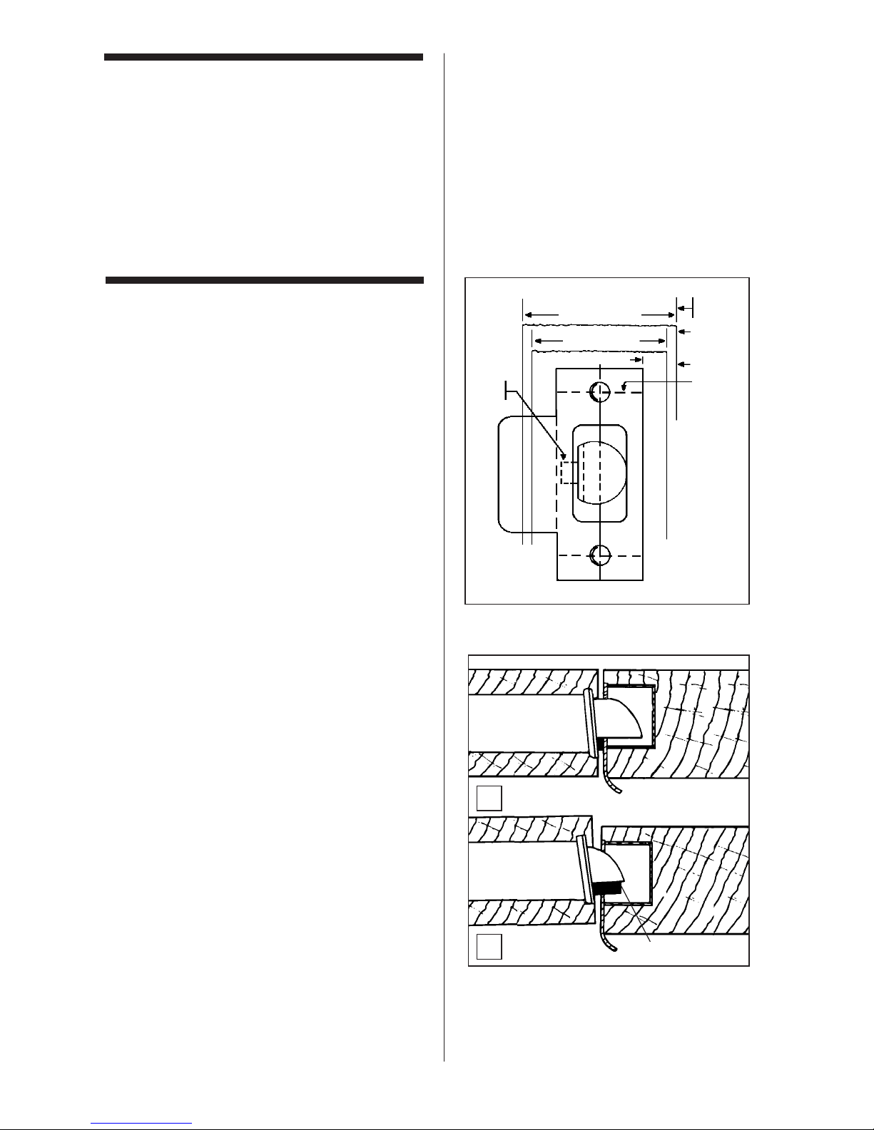
The door to frame relationship is critical for
the performance and durability of the
latch mechanism. The vertical and horizontal center lines are important when positioning the lock, the strike, and the latch, and
must be according to ANSI* standard
A115.2. To insure proper installation, you
must use the supplied strike plate.
Rubber bumpers (supplied with the lock)
may be required to properly align the door.
The adjustment becomes more significant
with metal frames, wood doors, and filler
plates when replacing existing hardware.
Figure 14-1 shows the proper alignment
between the door, the frame, the latch and
the strike plate.
When the door rests against the door stop
(A), the dead latch (B) should seat against
the strike plate. At this point, you will notice a
tolerance of
3
⁄32" (2 mm), basic according to
ANSI standards. If the door travels beyond
this tolerance, the dead latch may slip into
the strike box with the anti-friction device,
causing the latch to jam, and create a lock-in
and lock-out condition. (see A in figure 14-2).
This condition can be prevented by adding
bumpers to the door stop.
* American National Standards Institute —
contact KABA for further information.
La relación entre la puerta y el marco es
muy importante para el rendimiento y la
durabilidad del mecanismo que acciona el
pestillo. Las líneas centrales, horizontales y
verticales, son importantes cuando se coloca la cerradura, el cerradero y el pestillo.
Deben responder a la norma ANSI* A115.2.
Para realizar una instalación adecuada,
deberá usarse la placa del cerradero provista.
Quizá se requieran topes de caucho (que
vienen con la cerradura) para alinear
adecuadamente la puerta. El ajuste es más
importante en los casos de marcos de
metal, puertas de madera y placas de relleno, cuando se cambian los herrajes existentes. La ilustración 14-1 muestra la alineación adecuada entre la puerta, el marco,
el pestillo y la placa del cerradero.
Cuando la puerta llega hasta su tope (A), el
pin de seguridad (B) del pestillo debe
apoyarse contra la placa del cerradero. En
ese momento notará que existe una tolerancia de
3
⁄32" (2 mm), tolerancia estándar
según las normas ANSI. Si la puerta gira
más allá de esta tolerancia, el pin de seguridad puede deslizarse en la caja del cerradero con el
dispositivo antifricción, haciendo que el
pestillo se atasque y bloqueando el acceso
tanto desde el interior como desde el exterior (véase A en la ilustración 14-2).
Esta situación puede prevenirse añadiendo
otros topes al tope de la puerta.
* Instituto Nacional Estadounidense de
Normas - para más información sírvase
entrar en contacto con KABA.
Changing the
combination
Continued
8. Replace the tamperproof screw in the
top of the lock unit.
9. Repeat steps 1-8 for other side of door.
13
Mantenimiento del pestillo
Preserving the latch
14
27
Changement de la
combinaison
Suite
8. Remettez la vis antivol dans le trou
prévu à cet effet sur le dessus du
boîtier.
9. Répétez les étapes 1 à 8 pour l’autre
côté de la porte.
L'alignement entre la porte et le jambage est
primordial pour le bon fonctionnement et la
durabilité du mécanisme de verrouillage. Il
est très important de respecter les normes
ANSI* A115.2 ainsi que les axes vertical et
horizontal au moment de poser la serrure, la
gâche et le pêne. Pour une installation
adéquate, utilisez la gâche fournie.
Vous aurez peut-être à utiliser les butées de
caoutchouc fournies pour aligner la porte
correctement. L'ajustement est encore plus
important s'il s'agit de remplacer du matériel
déjà en place sur des huisseries de métal,
des portes en bois et des plaques de rcouvrement. La figure 14-1 illustre le bon alignement qui doit exister entre la porte, le jambage, le pêne et la gâche.
Quand la porte vient s'arrêter contre la
butée de porte, le pêne demi-tour doit
s'appuyer contre la gâche. Vous pourrez
noter un jeu de
3
⁄32" (2 mm), norme définie
par l'ANSI. Si la course de la porte n'est pas
limitée, le contre-pêne de sécurité risque de
glisser dans le logement de la gâche avec le
dispositif antifriction, interdisant l'accès de
l'intérieur comme de l'extérieur (voir A
figure 14-2).
Vous pouvez limiter l'ouverture de la porte
en installant des butées de caoutchouc sur
l’arrêt de porte.
* American National Standards Institute
(communiquez avec KABA pour obtenir de
plus amples renseignements)
Alignement entre la porte et
le jambage
1
15
⁄16"
(49mm)
3
⁄32"
(2mm)
11
⁄32"
(9mm)
1
3
⁄4"
(44mm)
B
A
A
3
X

28
Funcion de paso libre
Continuación
Preserving the latch
Continued
Instalación de los topes de caucho (provistos en el juego de accesorios - artículo “L”
en la lista de verificación).
1. Cierre la puerta y empújela, asegurándose de que el pin de seguridad se
apoya en la placa del cerradero.
2. Colocándose del lado donde va el tope
de la puerta, compruebe si quedan espacios entre la puerta y el tope, en los tres
lados del marco (izquierdo, derecho y
superior). Marque los lugares donde los
espacios son de unos
3
⁄16" (5 mm) (ver la
figura 14-2).
3. Asegúrese de que estos lugares no
tienen grasa ni polvo.
4. Saque la capa protectora de los topes sin
tocar la superficie adhesiva y péguelos
en los lugares que ha marcado.
5. Antes de hacer una prueba, deje pasar
24 horas para que el adhesivo cumpla su
función. Durante este período la puerta
puede abrirse y cerrarse normalmente.
14
49:'22/4- ";((+8 ;36+89 (provided in
accessory pack – item “L” on checklist)
1. Close door and apply pressure making
sure the dead latch rests on the strike
plate.
2. Standing on the door stop side of the
door, check for gaps between the door
and the door stop on all three sides of
the frame (left, right, and top). Mark
locations where the gaps are approximately
3
⁄16" (5 mm) (see figure 14-2).
3. Make sure these locations are free of
grease and dust.
4. Peel the bumpers from their protective
backing without touching the adhesive
surface and stick them on the marked
locations on the door stop.
5. Allow 24 hours for adhesive to set before
testing. Door may be operated normally
during this time.
Registro de combinaciones
Combination setting
record
Combination # Date
____________________________
____________________________
____________________________
____________________________
____________________________
____________________________
____________________________
____________________________
____________________________
No de Combinación # Fecha
____________________________
____________________________
____________________________
____________________________
____________________________
____________________________
____________________________
____________________________
____________________________
15

29
Alignement entre la porte et
le jambage
Suite
Installation des butées de caoutchouc qui se
trouve dans le paquet d’accessoires (accessoire J de la liste de vérification)
1. Fermez la porte et appliquer une
pression en vous assurant que le pêne
demii-tour vient s'appuyer contre la
gâche.
2. En vous plaçant du côté de l’arrêt de
porte, vérifiez le jeu entre la porte et la
butée de porte sur les trois côtés de
l’huisserie (gauche, droite et dessus).
Marquez tout emplacement dont le jeu
est d'environ
3
⁄16" (5 mm) (voir figure
14-2.)
3. Assurez-vous que ces emplacements
sont dépourvus de graisse ou de
poussière.
4. Enlevez la bande adhésive qui recouvre
les butées de caoutchouc sans toucher à
la surface collante et fixez-les à
l'emplacement marqué.
5. Attendez 24 heures avant de vérifier la
pose. Vous pouvez toutefois ouvrir et
fermer la porte entre temps.
Registre des combinaisons
Node la combinaison Date
____________________________
____________________________
____________________________
____________________________
____________________________
____________________________
____________________________
____________________________
____________________________

30
No existe ningún procedimiento para
averiguar la combinación desde la parte
delantera de la cerradura. Una combinación perdida deberá anularse quitando la
cámara de combinación de la caja de la cerradura; luego se podrá colocar una nueva
combinación.
Nota:
El procedimiento siguiente puede
utilizarse tanto para la cerradura interior
como exterior.
1. Quite la placa posterior de la cerradura
sacando los cuatro tornillos que van en
esa placa.
2. Levante la palanqueta (A) de la cámara
para sacarla del eje de control (B),
haciendo palanca con un destornillador
de cabeza plana (véase la ilustración 16-
1).
3. Quite el cojinete del eje (C).
4. Quite la cámara de combinación (D)
sacando los dos tornillos Phillips (E) que
hay en cada extremo de la cámara.
5. Quite la cubierta echada a un lado 3 del
compartimiento (A) de la cámara que
lleva la marca “KABA” (véase la ilustración 16-2) golpeando suavemente con
un destornillador el borde de la cubierta
en el extremo del eje de control de la
cámara (A) (véase la ilustración 16-3)
para separarla de las juntas (B).
6. Ponga la cámara sobre un lado como se
ilustra en figura 16-4.
7.
Mediante pinzas (u otra herramienta), quite
el aro “E” (B) del saliente de la placa de
desenganche (A) (ver figura 16-4),
después, levante suavemente el extremo
de la placa de desenganche (C) del
saliente (A).
Nota:
La placa de desenganche (C) está
sometida a la tensión de un muelle y se
levantará fácilmente si se le empuja hacia la
izquierda para disminuir la tensión. Gire la
placa de desenganche (C) lo suficiente
como para liberar los engranajes (D), pero
no más allá de donde se indica en la figura
16-5.
8. Apriete en la varilla de cierre (E). Ahora,
los engranajes (D) pueden girar libremente (ver figura 16-6).
Clearing a lost
combination
Anulacion de una
combinación perdida
16
There is no procedure for finding an
unknown combination from the front of the
lock. A lost combination must be cleared by
removing the combination chamber from the
lock housing, then a new combination can
be set.
5:+ The following procedures can be
used for both the inside and outside lock
assemblies.
1. Remove the back plate from the lock by
removing the four back plate screws.
2. Lift the chamber linkage (A) off of the control shaft (B) by prying up with a flat blade
screwdriver (see figure 16-1).
3. Remove the shaft bushing (C).
4. Remove the combination chamber (D) by
removing the two Phillips head screws
(E) at each end of the combination chamber.
5. Remove the 3 sided chamber cover (A)
marked “KABA” (see figure 16-2) by gently tapping the lip of the chamber cover at
the control shaft end of the chamber (A)
(see figure 16-3) with a screwdriver to
detach it from the staked joints (B).
6. Lay the chamber down on its side as shown
in figure 16-4.
7. With tweezers, or other tool, slide the “E”
ring (B) off the unlocking slide stud (A)
(see figure 16-4), then gently lift the end
of the unlocking slide (C) over the unlocking slide stud (A).
5:+ The unlocking slide (C) is under
spring tension and will be easier to lift if
pushed to the left to ease tension. Swing the
unlocking slide (C) sufficiently to clear the
gears (D), no further than shown in figure
16-5.
8. Depress the lockout slide (E). The gears
(D) are now free to rotate see figure 16-6.
9. Turn each gear (D) so that the gear
pockets (F) are aligned as in figure 16-6.
10.Return the unlocking slide (C) over the
unlocking slide stud (A) while making
certain the five toes (G) are engaged in
the five gear pockets (F). If necessary,
adjust each gear to make proper alignment between toes and gear slots (see
figures 16-6 & 16-7).

31
Il est impossible de retrouver une combinaison perdue à partir du clavier de la
serrure. Pour annuler une combinaison
perdue, vous devez enlever la chambre à
combinaison du boîtier de serrure, puis entrer une nouvelle combinaison.
les instructions suivantes peuvent
être exécutées pour les côtés extérieur et
intérieur.
1. Enlevez le palastre en desserrant les
quatre vis .
2. Soulevez le levier (A) de la chambre hors
de l’arbre de commande (B) à l'aide d'un
tournevis à lame plate (voir figure 16-1).
3. Enlevez la bague de l'arbre (C).
4. Démontez la chambre à combinaison (D)
en desserrant les deux vis Phillips (E) à
chaque extrémité de la chambre à
combinaison.
5. Enlevez les 3 côtés du couvercle (A) de
la chambre sur lequel est inscrit “KABA’’
(voir figure 16-2) en tapotant avec la lame
d’un tournevis sur la languette du
couvercle de la chambre à l’extrémité de
l’arbre de commande de la chambre (A)
(voir figure 16-3) pour la désengager des
pattes d'attache (B).
6. Mettez la chambre à combinaison à plat
comme indiqué sur la voir figure 16-4.
7. À l'aide de petites pinces ou d’un autre
outil, faites glisser la bague en E (B) hors
du goujon du coulisseau de déverrouillage (voir figure 16-4), puis soulevez
doucement l’extrémité de celui-ci (C)
au-dessus du goujon (A).
Le coulisseau de déverrouillage (C)
est à ressort; aussi, il sera plus facile de
le soulever vers la gauche. Tirez sur le
coulisseau de déverrouillage (C) de
manière à laisser voir les engrenages (D)
(voir figure 16-5).
8. Appuyez sur le coulisseau de verrouillage (E). Les engrenages (D) peuvent
fonctionner librement (voir figure 16-6).
9. Tournez les engrenages (D) de manière
à les aligner avec leur logement respectif
(F) comme sur la figure 16-6.
Annulation d'une combinaison
perdue
A
E
B
C
D
A
B
A
B
A
BC

32
9. Gire cada engranaje (D) para que cada
válvula del engranaje (F) se alinee, tal
como aparece en la figura 16-6.
10. Vuelva a colocar la placa de desenganche (C) sobre los salientes (A) asegurándose de que los cinco dientes (G)
se quedan engranados en sus lugares
respectivos (F). Si es necesario, ajuste
cada engranaje para alinear correctamente los dientes y las válvulas del
engranaje (ver figuras 16-6 y 16-7).
Vuelva a instalar el aro “E” (B) en el saliente
(A). Una vez que la cámara quede como
aparece en la ilustración 16-7, se podrá
volver a montar en la caja de la cerradura.
No trate de poner una combinación hasta que
toda la unidad se haya vuelto a montar.
MONTAJE
1. Vuelva a colocar la cubierta de la cámara
(A) que lleva la marca “KABA”. Asegúre
se de que las juntas (B) en las dos placas
de los extremos entran en las dos
ranuras de la cubierta posterior (ver la
ilustración 16-2).
2. Vuelva a colocar el cojinete del eje (B) con
la parte plana hacia arriba (ver figura 16-8).
3. Fije la cámara (D) con los dos tornillos
Phillips (E) que había sacado antes (ver
figura 16-8).
4. Vuelva a colocar la palanqueta de la
cámara (C) en el eje de control (F) (ver
figura 16-8).
5. Vuelva a colocar la placa posterior y fíjela
con los cuatro tornillos correspondientes.
PUESTA DE LA COMBINACIÓN
Ejecute los pasos siguientes en el orden
indicado.
1. Gire el pomo exterior hacia la derecha
hasta el tope y luego suéltelo.
2. Introduzca la nueva combinación.
3. Gire el pomo exterior hacia la derecha
hasta el tope, asegurándose de que el
pestillo se repliega completamente; luego
suelte el pomo para activar la nueva combinación.
4. Repita las etapas 2 y 3 antes de cerrar la
puerta para confirmar la combinación.
Clearing a lost
combination
Continued
Anulacion de una combinación
perdida
Continuación
16
Resecure the “E” ring (B) on the unlocking
slide stud (A). Your chamber now resembles
figure 16-7 and is ready for reassembly into
the lock housing.
Do not attempt to set a combination until the
complete unit has been reassembled.
"##$F F
1. Resecure the chamber cover (A) marked
KABA. Make sure the staked joints (B) on
both end plates fit through both slots on
the back cover (see figure 16-2).
Re-stake joints.
2. Resecure the shaft bushing (B) with flat
side facing up (see figure 16-8).
3. Secure the chamber (D) with the two
Phillips head screws (E) you removed
earlier (see figure 16-8).
4. Resecure the chamber linkage (C) onto
the control shaft (F) (see figure 16-8).
5. Replace the back plate and secure it with
the four back plate screws.
#$$F$F $
Perform the following steps in order.
1. Turn the outside knob once clockwise to
the stop position then release.
2. Enter the new combination.
3. Turn the outside knob clockwise to the
stop position, make sure the latch is fully
retracted, then release the knob to lock in
the new combination.
4. Repeat steps 2 & 3 before closing your
door to confirm code setting.

33
10Replacez le coulisseau de déverrouillage
(C) sur le goujon (A) en vous assurant que
les cinq pattes (G) sont bien engagées
dans leur logement respectif (F). Si nécessaire, ajustez les engrenages pour aligner correctement les pattes et les rainures
(voir figures 16-6 et 16-7.)
Replacez la bague en E sur le goujon. Votre
chambre à combinaison ressemble maintenant à la figure 16-7 et est prête à recevoir
son couvercle.
N’essayez pas d'entrer une nouvelle
combinaison tant que la serrure n'est pas
complètement remontée.
"@###""%"
1. Replacez le couvercle (A) de la chambre
sur lequel est inscrit KABA. Assurez-vous
que les pattes d'attache (B) s'engagent
dans les fentes du couvercle arrière (voir
figure 16-2).
2. Replacez la bague de l'arbre (B) , côté plat
sur le dessus (voir figure 16-8).
3. Fixez la chambre à combinaison (D) à
l'aide des deux vis Phillips retirées plus tôt
(voir figure 16-8).
4.
Replacez les leviers (C) de la chambre sur
l'arbre de commande (F) (voir figure 17-8).
5. Remontez le palastre et fixez-le à l'aide
des quatre vis.
"#$"$
#
Suivez les instructions ci-dessous:
1. Tournez la poignée extérieure dans le
sens des aiguilles d’une montre jusqu'en
fin de course, puis relâchez-la.
2. Entrez la nouvelle combinaison.
3. Tournez la poignée extérieure dans le
sens des aiguilles d’une montre jusqu'en
fin de course. Assurez-vous que le pêne
est complètement rétracté, puis relâchez
la poignée pour enregistrer la nouvelle
combinaison.
4. Répétez les étapes 2 et 3 avant de fermer
la porte pour confirmer l’enregistrement.
Annulation d'une combinaison
inconnue
Suite
D
C
E
D
C
AC
B
G
F
A
E
F
B
C
D

34
Cuando se gira el pomo exterior o interior, el pestillo siempre se repliega sin
apretar ningún botón.
La cerradura está en la combinación
cero.
Siga el procedimiento indicado para
cambiar la combinación, etapa 14,
página 26, omitiendo la etapa 3 (no
introduzca la combinación existente).
Después de introducir la nueva
combinación, la cerradura sólo funciona
una vez, luego no abre.
Al cambiar la combinación, los botones
no se apretaron completamente.
Consulte la etapa 17, en la página 34 Anulación de una combinación perdida.
Para obtener asistencia, puede
llamar al 1-800-849-TECH (8324)
5
.
Fuera de EE.UU. y Canadá, diríjase a
su distribuidor KABA.
Turning outside or inside knob always
retracts latch without depressing any
buttons.
Lock is in zero combination.
Follow the procedure for changing a
combination (Step 14 on page 26)
except omit step 3 (do not enter the
existing combination).
After entering a new combination, the
lock works one time only; then the lock
fails to open.
Buttons of intended combination were
not fully depressed when changing
combination.
Refer to
(Step 17 on page 34)
-
"Clearing a lost combination".
58,;8:.+8'99/9:'4)+)'22
58
;:9/*+%#'4*'4'*'62+'9+
)'22>5;8*+'2+8
Troubleshooting
Localización y reparación de
averías
17
?
Î
+
?
Î
+
?
Î
+
?
Î
+
?
= Symptom/problem
= Síntoma/problema
= Problème
= Possible cause
= Causa posible
= Cause possible
= Remedy
= Solución
= Solution
Î
+

35
Sous l'action de la poignée extérieure
ou intérieure, le pêne se rétracte sans
que vous n'ayez appuyé sur aucun
bouton.
La serrure ne possède aucune combinaison.
Vous reportez à l’étape 14,
Changement de la combinaison, page
26. Ne tenez pas compte de l'étape 3
(combinaison déjà existante).
Dès que la nouvelle combinaison est
entrée, la serrure fonctionne une
première fois, puis interdit l'accès par la
suite.
Les boutons-poussoirs de la combinaison choisie n'ont pas été pressés
complètement au moment du
changement de la combinaison.
Reportez-vous à l’étape 17, page 34,
Annulation d'une combinaison
inconnue.
!5;865;862;9*+8+9+/-4+3+4:9
)53659+8$
5;
!5;82D+=:B8/+;8*+9@%+:2+
'4'*''*8+99+?<5;9A<5:8+*/9
:8/(;:+;8
Dépannage
?
Î
+
?
Î
+

Kaba Access Control
2941 Indiana Avenue
Winston-Salem, NC 27105 USA
Tel: 800.849.8324 or 336.725.1331
Fax: 800.346.9640 or 336.725.3269
www.kabaaccess.com
PKG2282 0910
 Loading...