


B-Net 93 60
User Manual
01/2006

© Copyright by
Kaba Benzing GmbH
Albertistraße 3
D-78056 Villingen-Schwenningen
Phone +49 7720/603-0
Fax +49 7720/603-102
info@kaba-benzing.com
www.kaba-benzing.com
All rights reserved. The document and its parts are copyrighted. Only Kaba Benzing has the right to
commercialize, market and distribute this document. This document, or any part of it, may not be copied
or reproduced, adapted, arranged, reworked or modified without the prior consent of Kaba Benzing.
All company, trademark or product names are trademarks or registered trademarks of their re spective
owners and are protected.
Subject to technical changes without notice!
Order no. 04036695

1 About this manual...................................................................................................................5
2 Safety regulations...................................................................................................................7
2.1 Use as directed...............................................................................................................7
2.2 General remarks.............................................................................................................7
2.3 Installation instructions ...................................................................................................7
2.4 Handling of Lithium batteries..........................................................................................8
2.5 ESD (Electro Static Discharge) protective measures.....................................................9
3 Product description..............................................................................................................10
3.1 The B-Net 93 60 Terminal ............................................................................................10
3.2 Technical data ..............................................................................................................11
3.3 Conformity ....................................................................................................................13
3.4 Labeling ........................................................................................................................13
4 Design and function .............................................................................................................14
4.1 How to open the housing..............................................................................................14
4.2 Housing front ................................................................................................................15
4.2.1 Trimmer for display contrast.............................................................................15
4.3 Bottom casing...............................................................................................................16
4.3.1 Mains switch.....................................................................................................17
4.3.2 Buffer battery....................................................................................................17
5 Mounting and installation ....................................................................................................18
5.1 Installation conditions ...................................................................................................18
5.2 Installation scheme.......................................................................................................20
5.3 Installation lines............................................................................................................21
5.3.1 Power supply internal.......................................................................................21
5.3.2 Power supply external......................................................................................21
5.3.3 Subterminal......................................................................................................21
5.3.4 Door control......................................................................................................22
5.3.5 Host connection................................................................................................22
5.4 Wall-mounted installation..............................................................................................23
5.4.1 Direct surface mounting ...................................................................................23
5.4.2 Hole pattern......................................................................................................23
5.4.3 Using the mounting plate .................................................................................24
5.5 Insertion of the installation cables ................................................................................26
5.6 Connectors ...................................................................................................................27
5.6.1 Connections on BEX101 mother board and BECO500 CPU unit....................27
5.6.2 Ethernet connector...........................................................................................28
5.6.3 Optional serial interface or modem..................................................................28
5.6.4 Analog modem.................................................................................................29
5.6.5 ISDN modem....................................................................................................30
5.6.6 RS485 interface (BEX302)...............................................................................31
5.6.7 RS232 interface (BEX301)...............................................................................34
5.6.8 RJ-45 Connection for second reader...............................................................34
5.6.9 Digital inputs.....................................................................................................35
5.6.10 Relay outputs ...................................................................................................36
5.6.11 Input 24 V.........................................................................................................37
5.6.12 SV9001 power supply ......................................................................................38
5.7 Hardware options..........................................................................................................39
5.7.1 BEX400 memory expansion unit......................................................................39
5.7.2 Uninterruptible power supply BEX500 .............................................................40

6 Set-up.....................................................................................................................................42
6.1 Set-up process..............................................................................................................42
6.2 Set-up of optional hardware .........................................................................................43
6.2.1 Second reader (external reader, e.g. CCD hand scanner)..............................43
6.2.2 Replacing a reader module with other reader type..........................................43
6.2.3 Host connection via partyline ...........................................................................44
6.2.4 Host connection via modem.............................................................................44
6.2.5 Subterminal......................................................................................................45
6.3 Start options..................................................................................................................46
6.3.1 Function of buttons and LEDs..........................................................................46
6.3.2 Start of application............................................................................................47
6.3.3 Cold start of application....................................................................................47
6.3.4 Start of service mode .......................................................................................47
6.3.5 Start of service mode and reset to default IP...................................................47
7 BECO service module ..........................................................................................................48
7.1 Start of service module.................................................................................................48
7.2 Access to the service module.......................................................................................49
7.2.1 First access ......................................................................................................49
7.2.2 Access after executed network parameter setting...........................................49
7.3 Service functions ..........................................................................................................49
7.3.1 Demands on the HTTP browser.......................................................................49
7.3.2 Call of service functions ...................................................................................49
7.3.3 Log-in................................................................................................................50
7.3.4 Start page.........................................................................................................51
7.3.5 Overview of functions.......................................................................................52
7.3.6 System monitoring and maintenance...............................................................53
7.3.7 Hardware settings ............................................................................................62
7.3.8 Hardware analysis............................................................................................74
7.4 FTP access...................................................................................................................77
8 Operating elements ..............................................................................................................78
8.1 Badge input...................................................................................................................78
8.1.1 Contactless media............................................................................................78
8.1.2 Mag-stripe badges and barcode badges..........................................................79
8.1.3 Inductive badges..............................................................................................80
8.1.4 Verification LEGIC® & Fingerprint ...................................................................81
8.2 Matrix touch ..................................................................................................................82
8.3 Display illumination.......................................................................................................83
9 Maintenance ..........................................................................................................................84
9.1 Battery change..............................................................................................................84
10 Packaging / returns...............................................................................................................85
10.1 Devices.........................................................................................................................85
10.2 Electronic assemblies...................................................................................................85
10.3 Labeling ........................................................................................................................86
11 Disposal.................................................................................................................................87
12 Appendix................................................................................................................................88
12.1 Dimensional drawings...................................................................................................88
12.2 Exchange of passepartout............................................................................................89
13 Index.......................................................................................................................................91

User Manual B-Net 93 60 About this manual
01/2006 © Kaba Benzing GmbH 5
1 About this manual
Validity
This Manual describes the Kaba Benzing B-Net 93 60 terminal as of
Serial number: 072363 - 000500
Manufacturing date: September 2005
Boot loader version: 2.4.0
Service module version: 698-00-X-K03
Addressees
The manual addresses specialists for mounting, installation, set-up, service, and
maintenance of the device.
The descriptions in this manual require trained personnel. The information in this
manual does not substitute for product training.
Content and
purpose
The contents are limited to the assembly, installation, set-up, and basic operation of
the hardware.
Supplemental
documentation
Information regarding the application used by this terminal can be found in
• Software Manual B-Client HR3 /753, order number 04036907.
When installing the device the following remarks listed in the following Kaba
Benzing manual must be considered.
• General installation notes, order number 04023965.
The above mentioned manuals can be found in the included
• Documentation & Software CD ROM, order number 04033324.
Modification log
Listed below are the most important changes and additions compared to the last
edition of the B-Net 93 60 User Manual, 10/2005.
• Connection of subterminals, refer to chapter
5.6.6
• Changed specification of the subpartyline buslines
• Extendet description of the subpartyline
Orientation in
the manual
This manual contains the following orientation guide to easier find specific topics:
• The table of contents in the beginning of the manual shows an overview of all
topics.
• The header always contains the respective main chapter.
• An index in alphabetical order is at the end of the manual.
About this manual User Manual B-Net 93 60
6 © Kaba Benzing GmbH 01/2006
Danger
categories
Remarks with specifications or rules and restriction to prevent injuries and property
damage are particularly marked.
Please read the danger warnings and user tips carefully. This information will help
prevent accidents and damage to your equipment.
Danger warnings are divided into the following categories.
WARNING
Describes a possibly dangerous situation that can lead to substantial bodily harm or
that can lead to death.
CAUTION
Describes a possibly dangerous situation that can lead to minor injuries.
CAUTION
Describes a possibly dangerous situation where the product itself or something near
the product could be damaged.
Symbols
If the source of danger can be precisely specified the respective symbol is prefixed.
Hazardous voltage
Explosion hazard
Danger for electronic components due to electrostatic discharge
Remarks with
symbols
Please pay special attention to the remarks that are marked with symbols. The
symbols used in this manual have the following meaning:
NOTICE!
Important information for proper handling of the product. Ignoring this information
can cause device malfunction.
Remark
Tips and useful information. This information will help you to best use the product
and its functionality.

User Manual B-Net 93 60 Safety regulations
01/2006 © Kaba Benzing GmbH 7
2 Safety regulations
2.1 Use as directed
The device or system is only intended for usage as described in chapter ”Product
Description.”
Use going beyond that is not according to rules. The manufacturer is not
responsible for damages resulting from improper use. The user/operator is
responsible for any risks associated with non-duly use.
2.2 General remarks
WARNING
Hazardous voltage inside the housing!
Carelessness can lead to an electric shock.
Only skilled maintenance or service personnel may open the housing. Before you
carry out maintenance works take the following measures:
• Disconnect power.
• Secure against re-starting.
• Verify that the installation is dead.
Removal of malfunctions and maintenance may only be performed by skilled
technical specialists.
Only specialists authorized by the manufacturer may carry out reconstruction and
modification.
All reconstructions and modifications carried out by unauthorized personnel leads
to an exclusion of liability.
2.3 Installation instructions
Installations at the mains voltage may only be executed by a trained electrical
specialist.
Only trained personnel may carry out mounting and installation.
Kaba Benzing GmbH is not liable for damages resulting from improper handling or
incorrect installation.
NOTICE!
The relays are designed for 30 V AC / DC and 2 A maximum.
For device safety reasons 115 / 230 V may not be switched with this relay.
Installation may only be carried out in places that fulfill climatic and technical
conditions stated by the manufacturer.
NOTICE!
Devices that are installed outside or in splash-water endangered rooms, may not be
operated with 115 / 230 V mains voltage, but must be supplied with safety extra-low
voltage (24 V).

Safety regulations User Manual B-Net 93 60
8 © Kaba Benzing GmbH 01/2006
2.4 Handling of Lithium batteries
CAUTION
Lithium batteries can rupture or burst like an explosive.
Improper handling of Lithium batteries can lead to fire and explosions.
• Only skilled specialists authorized by the manufacturer may exchange
Lithium batteries.
• They may only be replaced by batteries of the same type.
• Do not open, bore through, or crush Lithium batteries.
• Do not burn Lithium batteries or expose to high temperatures.
• Do not short-circuit Lithium batteries.
The Lithium-ion accumulator Panasonic CGA103450 is used as buffer battery in
the BEX500 UPS (optional).
These batteries may only be charged with the BEX500’s charging connection.
The Lithium Mangandioxid battery type CR 2032 is used to buffer the memory on
the BEC0500 CPU board and the BEX400 add-on memory.
These batteries may in no case be recharged. The battery could overheat and melt
while being recharged or even explode.
NOTICE!
Used Lithium batteries must be disposed of according to state and local regulations.
Please carefully deposit the batteries that must be disposed, in order to avoid short-
circuits, crushing, or damage of the battery housing.

User Manual B-Net 93 60 Safety regulations
01/2006 © Kaba Benzing GmbH 9
2.5 ESD (Electro Static Discharge) protective measures
CAUTION
Danger for electronic components due to electrostatic discharge.
Improper handling of printed circuit boards or components can cause damages that
lead to complete failures or sporadic errors.
During installation and repair of the device, the ESD protective measures must be
considered.
Please consider the following guidelines before the installation or maintenance of
the device:
• If you deal with electronic components, always carry a wristband for the
protection against electrostatic discharge. Connect one part of the wristband
with a discharge socket or an unvarnished grounded metal component.
• Only touch the printed circuit boards at the edges. Do not touch the printed
circuit board itself or the connector.
• Place all dismantled components on an anti-static surface or in a static-proof
container.
• Avoid contact between printed circuit boards and your clothing. The
wristband only protects the printed circuit boards against electrostatic
discharge from the body, but there is still a risk of damage through
electrostatic discharge from your clothing.
• Only transport and dispatch dismantled modules in protective bags.
Product description User Manual B-Net 93 60
10 © Kaba Benzing GmbH 01/2006
3 Product description
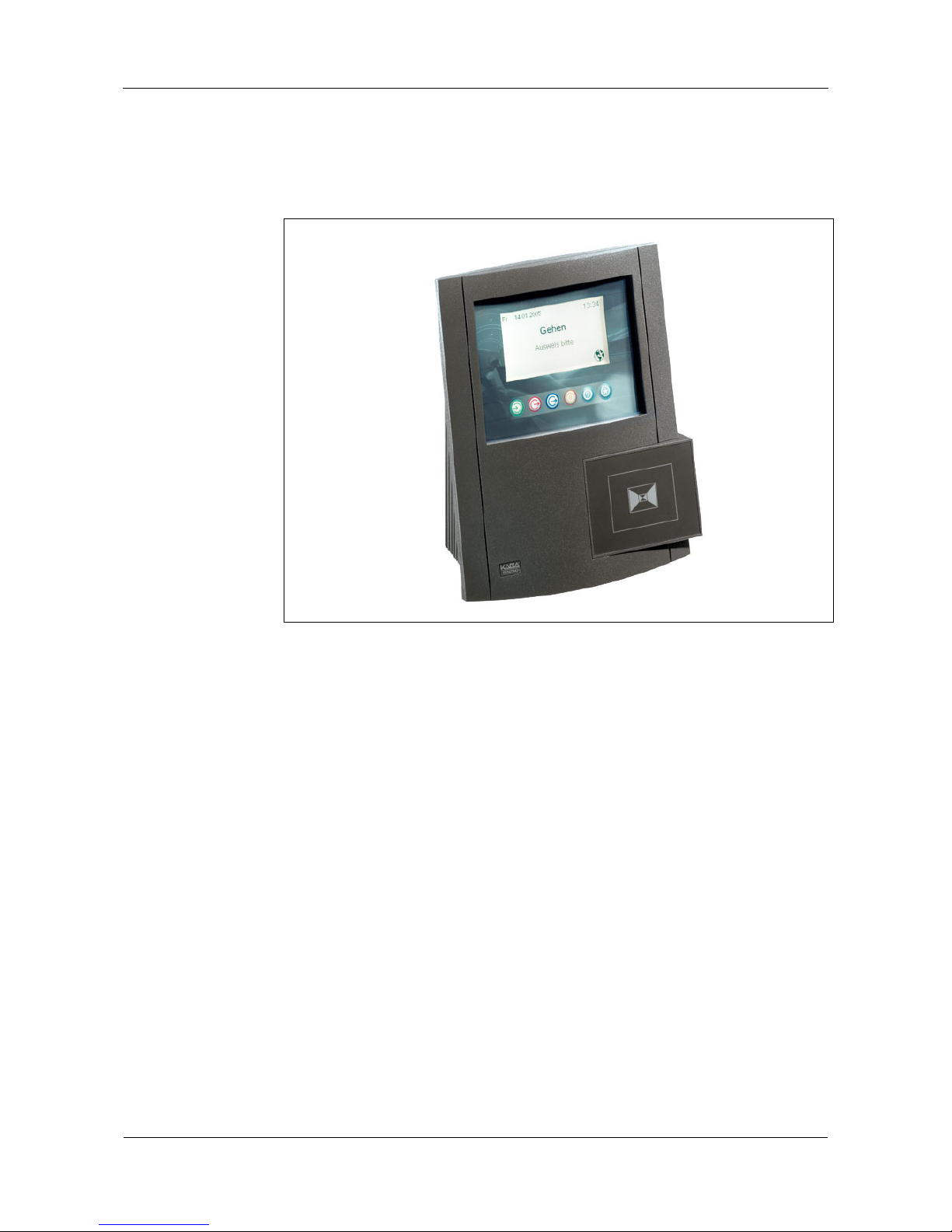
3.1 The B-Net 93 60 Terminal
Fig. 1: B-Net 93 60
The B-Net 93 60 is a terminal with state-of-the-art technology. Besides its primary
time recording functions, the 93 60 can handle additional tasks, such as access
control functions or simple PDC functions as well as project time recording.
The terminal software can be updated any time via a network connection.
The terminal features a high-contrast monochrome display with a resolution of
240 x 128 pixels. The device is operated via a 8 x 8 matrix touch where operational
elements can be designed and placed individually.
Time data capture is performed with the keyless LEGIC® identification system.
Reader modules are also available, including inductive; mag-stripe, barcode, chipcard; and contact-free readers such as Mifare, HID, and Hitag.
Up to four Bedanet subterminals can be connected optionally.
The built-in Ethernet interface allows integration into existing IT structures.
The terminal has 2 outputs (relays) and 4 digital inputs for control functions.

User Manual B-Net 93 60 Product description
01/2006 © Kaba Benzing GmbH 11
3.2 Technical data
System Processor
Netsilicon NET+ARM50 ( ARM7TDMI – Core )
Memory
16MByte SDRAM / 8MByte FLASH / 1MByte SRAM,
buffered, expandable by 4 MByte to 5 MByte
Display
Monochrome display with a resolution of 240 x 128
pixels
Keypad
8 x 8 matrix touch
alphanumeric reader keypad (optional)
Communication
Ethernet interface 10/100 Mbps auto-sensing (Twisted
Pair).
Alternatively:
• Partyline RS 485 (optional)
• Analog modem (optional)
• ISDN modem (optional)
Reader
Serial reader module integrated.
Available reader types: LEGIC®, inductive, mag-stripe,
barcode, verification LEGIC® & Fingerprint. Other
readers available on request.
with
SV9001 230 V
with
SV9001 115 V
Rated voltage
24 V AC/DC 230 V 115 V
Voltage range
12 -27 V AC
16 -32 V DC
+6 / -10% +6 / -10%
Frequency
50 -60 Hz 50 -60 Hz 50 -60 Hz
Power supply
Power consumption
25 W max. 25 VA max. 25 VA max.
Protection class
according to IEC 60529
IP54 with LEGIC®, barcode, and Verification LEGIC®
fingerprint reader modules.
IP30 with mag-stripe and inductive reader modules.
Relative humidity
10% to 95%, non-condensing.
Ambient temperature
-10°C to +40°C, no direct sunlight.
Environmental
conditions
Use
Indoors and in protected outdoor areas.
Height
300 mm
Width
251 mm
Dimensions
Depth
120 mm
Product description User Manual B-Net 93 60
12 © Kaba Benzing GmbH 01/2006
Memory size 1 MB (Standard) 5 MB (optional)
Data records
8,000 alternatively 3,000 50,000
Capacity of data
memory
Master records
2,000 alternatively 3,500 10,000
These specifications apply in connection with the B-Client HR3 application.
Data retention in
case of power
failure
Modified parameters, master records, and data records are retained approximately
6 months without power supply.
Buffer time
The optional BEX500 uninterruptible power supply allows for further operation after
power failure.
Buffer time (operating time with full function) for devices with BEX500 is in case of
heavy frequentation at least 90 minutes; however under typical conditions up to
4 hours.
These specifications apply to a new, fully charged accumulator in room
temperature.
NOTICE!
Supplying the door opener with power through the BEX500 UPS is not possible.
User Manual B-Net 93 60 Product description
01/2006 © Kaba Benzing GmbH 13
3.3 Conformity
This device complies with the standards
EN 55022
EN 61000-6-1
EN 61000-6-2
EN 300330
according to the regulations of the EU guidelines
73/23/EWG
Low voltage directive
89/336/EWG
EMC standard
FCC Compliance
This device complies with Part 15 of the FCC Rules. Operation is subject to the
following two conditions:
(1) This device may not cause harmful interference, and
(2) this device must accept an y interference received, including interference that
may cause undesired operation.
NOTICE!
Any changes or modifications not expressly approved by the party responsible for
compliance could void the user's authority to operate the equipment.
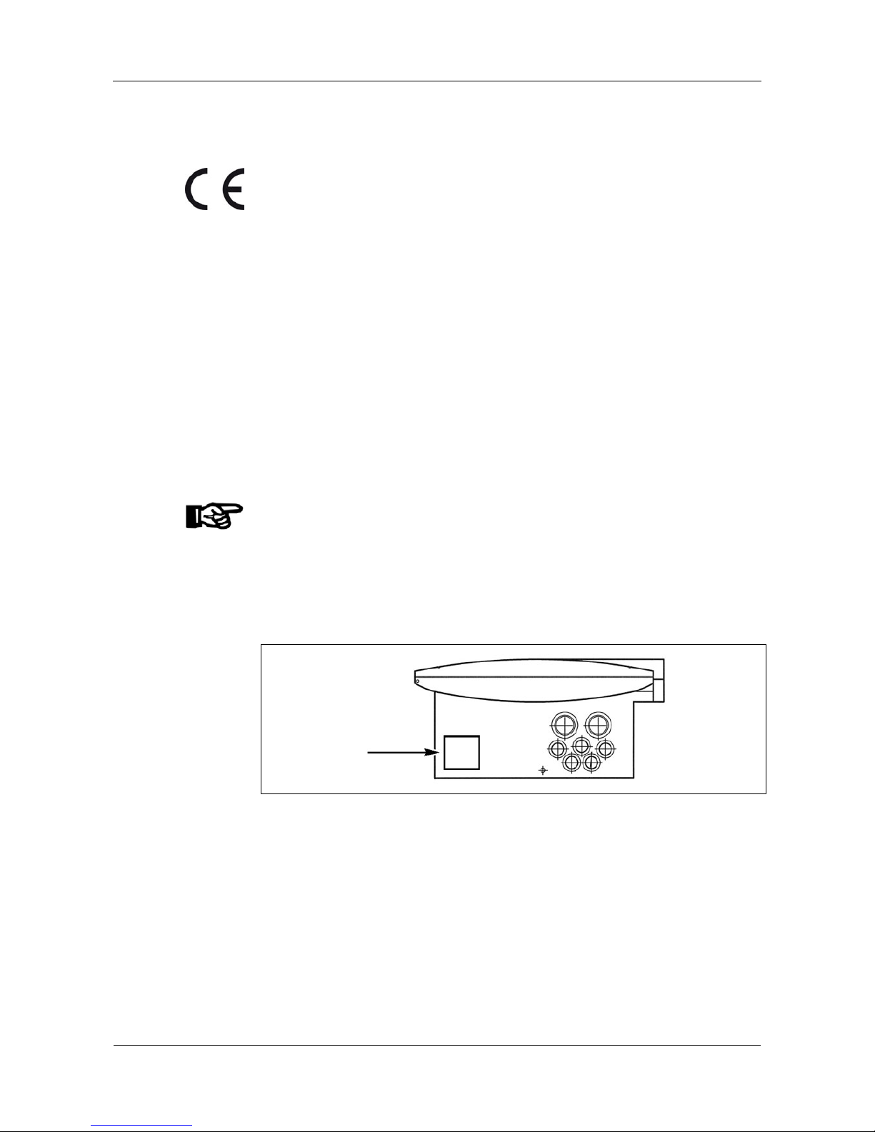
3.4 Labeling
The identification plate is located on the bottom side of the device.
Fig. 2: Position of identification plate
On the identification plate are:
• Device name
• Product number
• Serial number
• Power data
• CE identification
• WEEE specification according to DIN EN 50419, please refer to chapter
11

Design and function User Manual B-Net 93 60
14 © Kaba Benzing GmbH 01/2006
4 Design and function
4.1 How to open the housing
WARNING
Hazardous voltage at clamps
Carelessness can lead to an electric shock.
• Only skilled maintenance or service personnel may open the housing.
• Disconnect power before servicing.
• Voltage must be turned off for devices that are connected fix.
• Devices that are fed via a separable connection, the mains plug must
be pulled out.
• Secure against re-starting.
• Verify that the installation is dead.
To open the housing, please proceed as follows:
• Unlock housing front with key.
• Swing housing front to the left.
Fig. 3: How to open the housing

User Manual B-Net 93 60 Design and function
01/2006 © Kaba Benzing GmbH 15
4.2 Housing front
CAUTION
Display operating voltage 310 V AC (6 mA max.)
Hazard of electric shock
Avoid touching the area marked in yellow!
Fig. 4: B-Net 93 60 housing front with matrix touch
1 Serial reader module
2 BEX201 user interface
3 Display module
4 Trimmer for display contrast
5 BEX500 UPS (optional)
4.2.1 Trimmer for display contrast
The display contrast is set by default. Due to special conditions at the installation
site (light incidence), the contrast setting may need to be corrected again.
NOTICE!
The device has an automatic temperature-sensitive contrast control. Therefore, the
display contrast settings should only be carried out after the device has already
been operated for at least one hour with a closed housing.
Design and function User Manual B-Net 93 60
16 © Kaba Benzing GmbH 01/2006
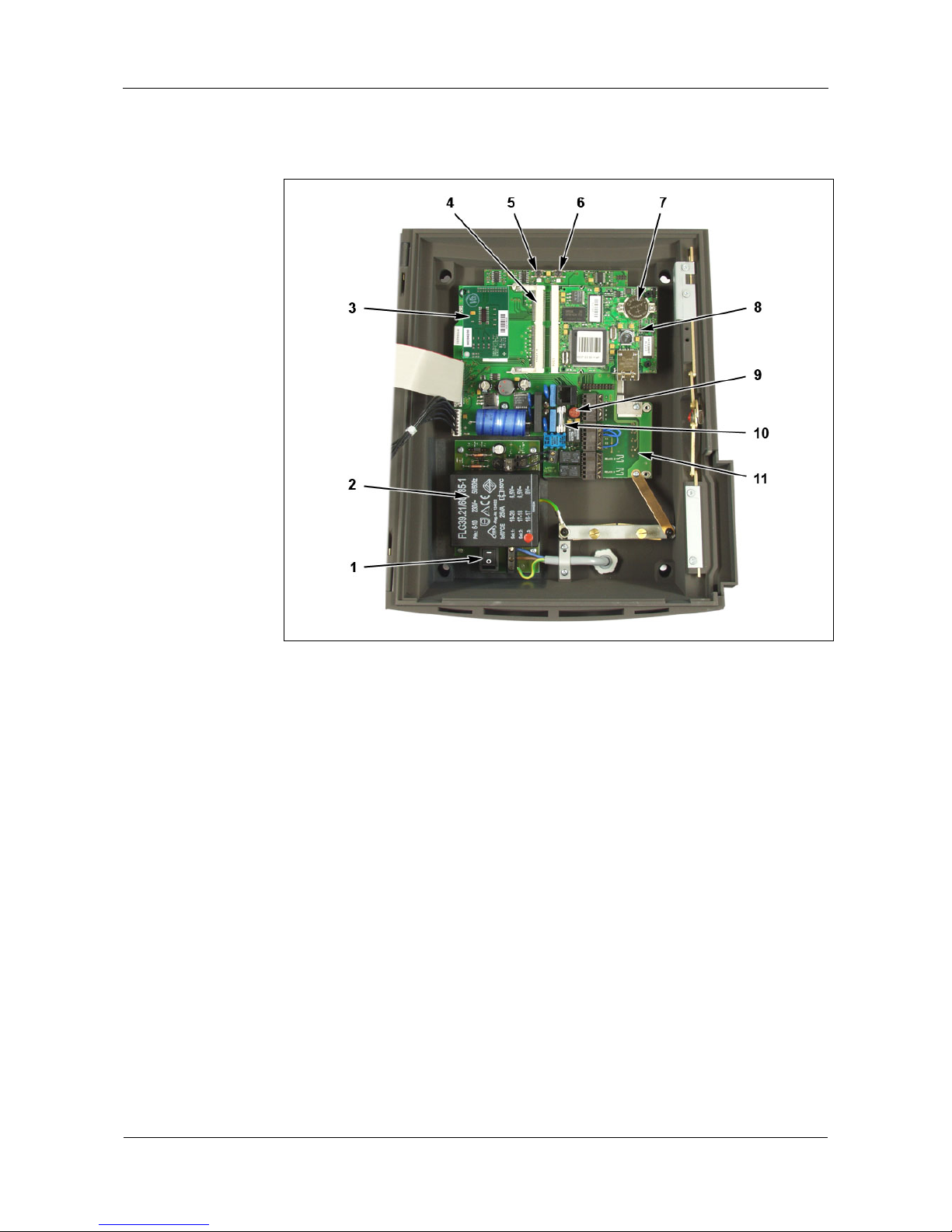
4.3 Bottom casing
Fig. 5: Bottom casing
1 Mains switch
2 SV9001 power supply (optional)
3 Optional interface or modem, refer to chapter
5.6.3
4 Slot for BEX400 memory expansion module
5 Cold start button, refer to chapter
6.3
6 Service button, refer to chapter
6.3
7 Backup battery CR2032
8 BECO500 CPU unit
9 Subminiature fuse (radial) F 315 mA / 250 V
5 V supply for second reader at RJ-45 connector on BEX101
10 Microfuse 5x20 (cartridge fuse) T 1.6 A / 250 V
input circuit of 24 V terminal supply
11 BEX101 board
User Manual B-Net 93 60 Design and function
01/2006 © Kaba Benzing GmbH 17
4.3.1 Mains switch
The mains switch is located on the SV9001 power supply unit.
Remark
The internal SV9001 power supply unit with mains switch is optional and therefore
not available in devices with external 24 V power supply.
4.3.2 Buffer battery
To buffer modified parameters, master records, and data records, a Lithium battery
type CR2032 is located on the BECO500 CPU board.
NOTICE!
The buffer battery must be replaced by a new one every two years.
Please refer to chapter
9.1 Battery change .

Mounting and installation User Manual B-Net 93 60
18 © Kaba Benzing GmbH 01/2006
5 Mounting and installation
5.1 Installation conditions
General
An accurate installation of all components is a basic requirement for proper
functioning. The following installation instructions must be adhered to.
Connectors
At the terminal’s installation site, the appropriate Ethernet connection as well as a
mains voltage supply must be prepared. Mains voltage supply can be executed as
stationary wiring or as separable connection.
NOTICE!
If the mains voltage supply is executed as separable connection the following
applies:
• The mains socket must be in the immediate vicinity of the device.
• The mains plug must be freely accessible.
For devices without an integrated power supply, the 24 V supply voltage can be
supplied by the external power supply.
Earthing
The terminal must be grounded!
In order to ensure an ideal shielding according to EMC (electromagnetic
compatibility), the conductive housing interior must be connected with earth.
If an internal SV 9001 power supply (optional) is available, the earth lead must be
connected to it.
If no internal power supply is available, the earth lead must be routed via the
external power supply and clamped to the metal holder.
Cable inlet
The network connection, the mains voltage supply, and possibly needed signal lines
can be inserted into the housing from below or from the back. Perforated holes to
insert the installation cables are available in the bottom casing.
NOTICE!
If connections are made from the back of the housing the mounting position must be
defined at an early stage and discussed with the electrical fitter.
Sun
exposure
Direct illumination as well as sun exposure leads to reflections within the display
area and a poor readability of the display.
NOTICE!
Please avoid installation in places with direct sunlight.

User Manual B-Net 93 60 Mounting and installation
01/2006 © Kaba Benzing GmbH 19
Splash water
Devices that are installed outside or in splash-water endangered rooms, may not be
connected to the 115 V / 230 V mains voltage, but must be supplied with safety
extra-low voltage (24 V).
In this case, industry-standard and waterproof screwed cable glands are to be
used for the insertion of the lines into the housing.
Please consider that the International Protection class depends on the type of
reader being used.
NOTICE!
Please arrange for a weather protection roof if installed outside.
Clearances
Between two devices with LEGIC® readers a distance of 20 cm must be observed
on all sides.
Min. 20 cm
Min. 20 cm
Min. 20 cm
Fig. 6: Minimum distance between devices with LEGIC® readers
Mounting height
Recommended mounting height: 150 cm to top edge of terminal.
150 cm
Fig. 7: Recommended mounting height

Mounting and installation User Manual B-Net 93 60
20 © Kaba Benzing GmbH 01/2006
5.2 Installation scheme
5
3
1
2
115 V / 230 V AC
4
7
8
9
10
11
12
13
6
Fig. 8: B-Net 93 60 installation scheme
1 Power supply internal* 8 Subterminal
2 Power supply external* 9 External power supply e.g. SV905
3 Data line subterminal 10 Door-opener push button
4 Door control 11 Door-frame contact
5 Host connection 12 Door han dle contact, door opener, and bolt
contact
6 B-Net 93 60 13 Door ope ner door 2
7 Host computer
* alternatively

User Manual B-Net 93 60 Mounting and installation
01/2006 © Kaba Benzing GmbH 21
5.3 Installation lines
5.3.1 Power supply internal
With devices that have an integrated power supply SV9001 (optional), the mains
voltage supply is led to the terminal.
What must be considered?
The terminal blocks on the SV9001 power supply are designed for a wire cross
section of 1.5 mm² maximum.
Line requirements
Power cord max. 3 x 1.5 mm
2
.
5.3.2 Power supply external
Devices with 24 V input are fed with an external power supply,
e.g. SV900 item no. 04021688 or SV905 item no.04033373.
What must be considered?
The terminal’s housing must be grounded. It is therefore imperative to carry the
ground wire from the power supply to the terminal.
In case of long lines, the voltage drop --caused by the line resistance-- must be
considered.
Line requirements
Cables with a cable diameter from 0.5 mm to 0.8 mm can be used.
Three wires are required for power supply + earth (SV900).
If door-opener voltage is required, two further wires are needed (SV905).
Recommended cable
CAT.5 S-UTP 4 x 2 AWG 24 or AWG 22 (according to EIA/TIA568) or higher.
5.3.3 Subterminal
The subterminals are connected via a 2-wire sub-partyline. It can be designed in
star-shape or as partyline.
What must be considered?
No further signals or voltages may be carried along inside the data cable to the
subterminal (e.g. door-opener triggering, door-frame contact, etc.).
A separate power supply must be provided for the subterminals.
The supply voltage for the subterminals may not
be taken from the terminal, it may
also not
be carried along within the data cable.
The complete bus connection (master lines and branch lines) may be up to 2,000
meters long. One branch line may not exceed 100 m.
Line requirements
Shielded line with twisted wire pairs,
for instance standard telephone cable J-Y (St) Y 2 x 2 x 0.6 mm.
Recommended cable
CAT.5 S-UTP 4 x 2 AWG 24 or AWG 22 (according to EIA/TIA568) or higher.

Mounting and installation User Manual B-Net 93 60
22 © Kaba Benzing GmbH 01/2006
5.3.4 Door control
Line to door-opener, door-frame contact, door-opener push button, door handle
contact, etc.
Line requirements
Cables with a cable diameter from 0.5 mm to 0.8 mm can be used.
Recommended cable
CAT.5 S-UTP 4 x 2 AWG 24 or AWG 22 (according to EIA/TIA568) or higher.
5.3.5 Host connection
Ethernet
Connecting cable from terminal to the Ethernet’s RJ45 connector.
Line requirements
Connection takes place via 1:1 patch cable.
Analog modem
Connecting cable from terminal to TAE outlet.
Recommended cable
Data cable with TAE jack 3 m long, item no. 04106703.
ISDN modem
Connecting cable from terminal to RJ45 outlet.
Recommended cable
Telephone cable with RJ45 jack 3 m long, item no. 04106702.
Partyline
What must be considered?
The complete bus connection (master lines and branch lines) may be up to 2,000
meters long. One branch line may not exceed 100 m.
A maximum of 30 devices may be operated with one partyline.
The length of the master line or the branch line can be increased with repeaters.
Please keep in mind that the connecting line of a repeater may not exceed
1,500 m. Up to 3 repeaters may be cascaded in an extension of a bus connection.
Line requirements
Shielded line with twisted wire pairs,
for instance standard telephone cable J-Y (St) Y 4 x 2 x 0.6 mm.
Recommended cable
CAT.5 S-UTP 4 x 2 x AWG 24 or AWG 22 (nach EIA/TIA 568), or higher (CAT.6,
CAT.7).
User Manual B-Net 93 60 Mounting and installation
01/2006 © Kaba Benzing GmbH 23
5.4 Wall-mounted installation
5.4.1 Direct surface mounting
With dowels / screws the terminal can be mounted directly to the wall.
For attachment, four mounting holes are available in the bottom casing. After
opening the device, the mounting holes are accessible in the housing corner s of
the bottom casing.
In case of soft mounting undergrounds, make sure that when installed, the housing
is not pressed into the underground.
The unevenness of the mounting surface may not exceed 0.5 mm. With spacing
washers for example, a possible unevenness must be compensated or adjusted.
Recommended mounting material:
• 4 x dowel S6
• 4 x round-head wood screw DIN 96 Ø 4.5 x 35
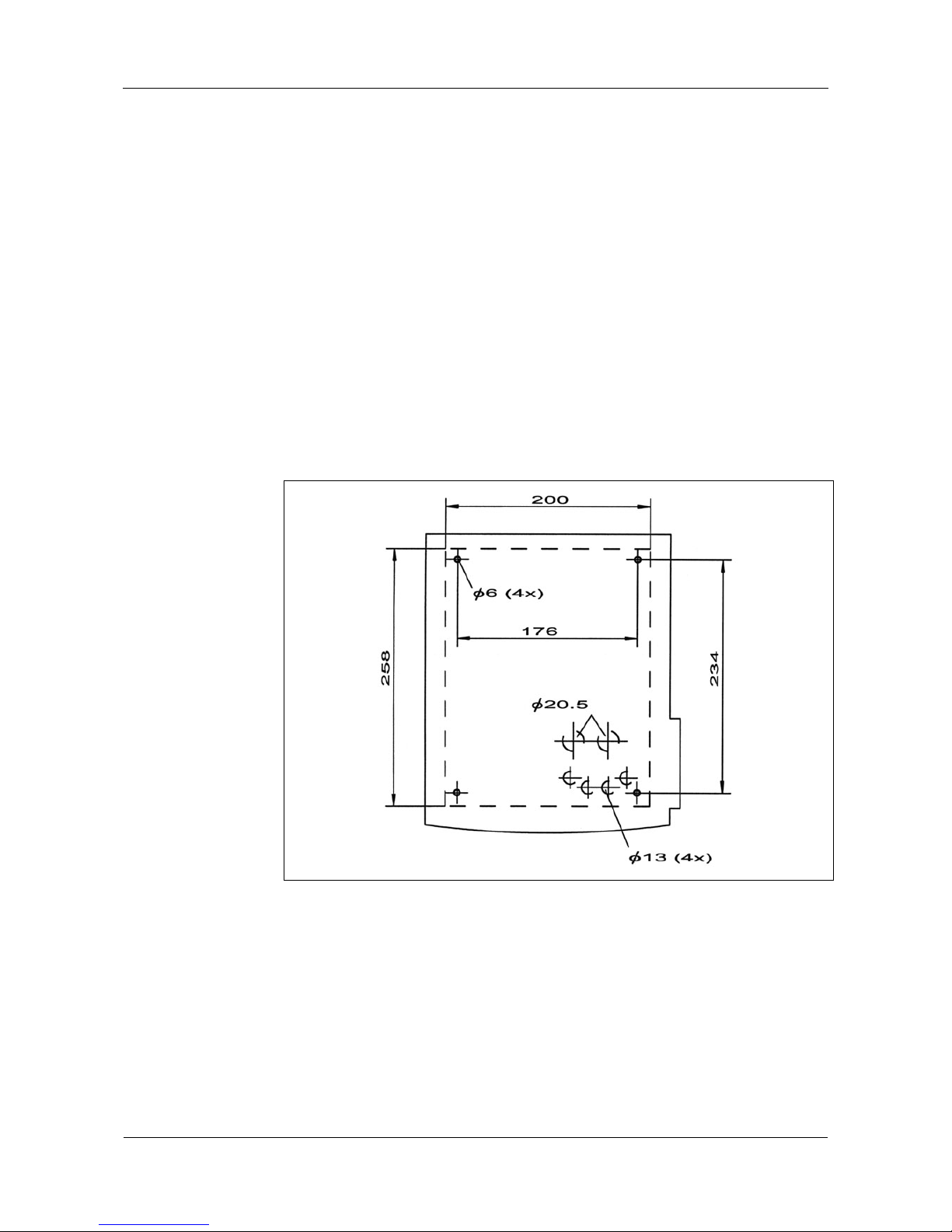
5.4.2 Hole pattern
Fig. 9: Hole pattern with mounting dimension, dimensions in mm
Mounting and installation User Manual B-Net 93 60
24 © Kaba Benzing GmbH 01/2006
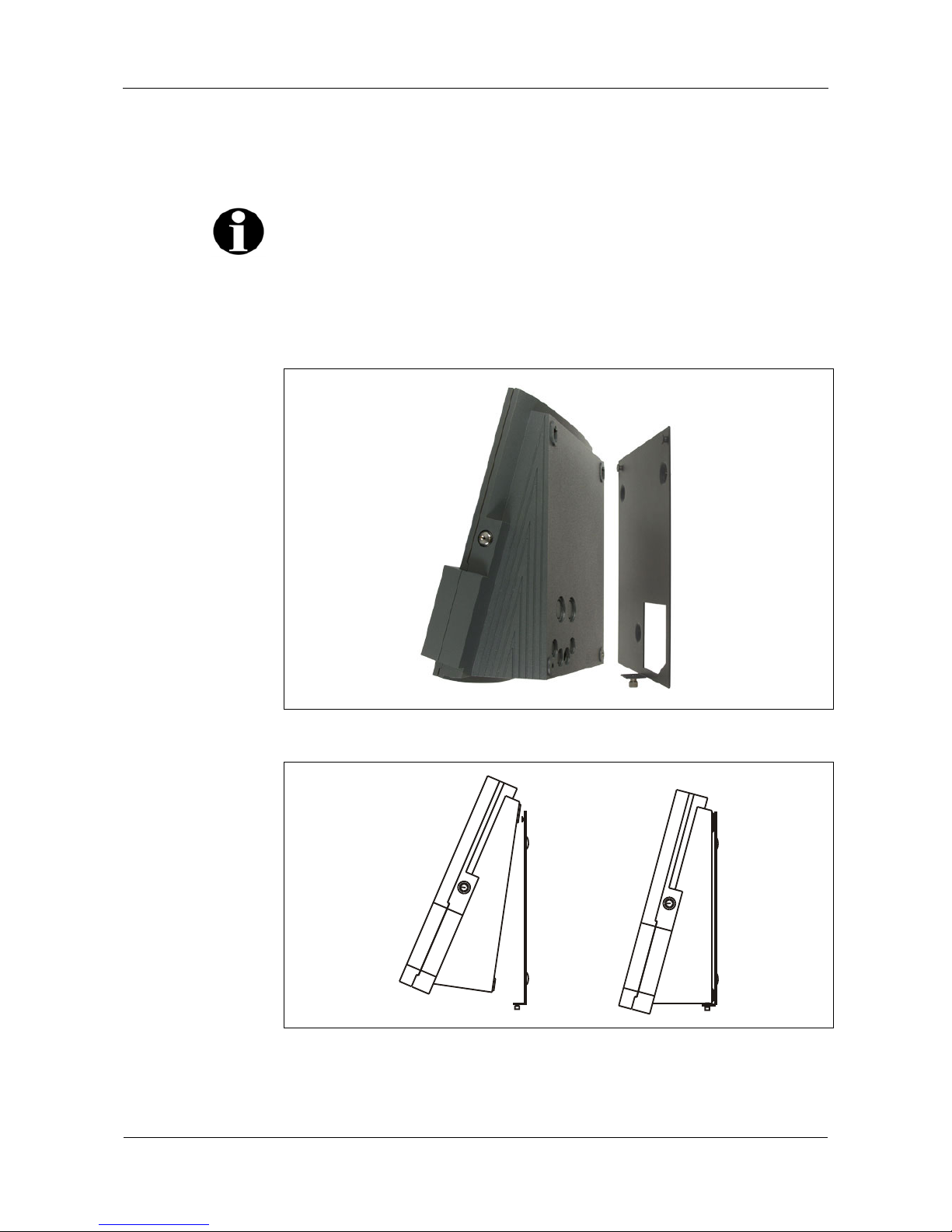
5.4.3 Using the mounting plate
If you install the terminal using the mounting plate, the terminal can be quickly and
easily removed from the wall.
Remark
The mounting plate --product number 04036599-- is an optional accesssory and
must therefore be ordered separately!
To mount the plate to the wall, 3 drill holes are provided.
After you attach the mounting plate to the wall, attach the terminal to the mounting
plate using the two mounting holes on the back of the terminal. For protection,
tighten the knurled screw at the lower end of the plate.
Fig. 10: Terminal and mounting plate
Fig. 11: Wall mounting with mounting plate

User Manual B-Net 93 60 Mounting and installation
01/2006 © Kaba Benzing GmbH 25
23,5
259,5
1
,5
6
20 160
44,5168
6 (3x)
70
Fig. 12: Hole pattern and dimensional drawing of mounting plate

Mounting and installation User Manual B-Net 93 60
26 © Kaba Benzing GmbH 01/2006
5.5 Insertion of the installation cables
Perforated holes to insert the installation cables are available (from below and from
the back).
Cable inlet should preferably be done from the back.
Fig. 13: Insertion of the installation cables
1 Cable inlet
2 Cable clamp
The incoming data line and the installation cables must be clamped under the clip
in such a way that a conducting connection between the shielding and cable clamp
develops.
Remark
2 cable fittings PG22, 4 grommets, and a blanking plug are included in delivery.

User Manual B-Net 93 60 Mounting and installation
01/2006 © Kaba Benzing GmbH 27
5.6 Connectors
5.6.1 Connections on BEX101 mother bo ard and BECO500 CPU unit
6
5
4
3
2
1
GND
GND
E4
E3
E2
E1
RELAIS 1
RELAIS 2
4
5
6
Fig. 14: Connections on BEX101 mother board and BECO500 CPU unit
1 Slot for optional serial interface or modem, refer to chapter
5.6.3
2 RJ-45 connector for second reader, refer to chapter
5.6.8
3 RJ-45 Ethernet connection, refer to chapter
5.6.2
4 Clamps for the serial interface, refer to chapter
5.6.3
5 Digital inputs, refer to chapter
5.6.9
6 Relay outputs, refer to chapter
5.6.10
7 Input 24 V AC / DC supply voltage for the terminal, refer to chapter
5.6.11
Mounting and installation User Manual B-Net 93 60
28 © Kaba Benzing GmbH 01/2006
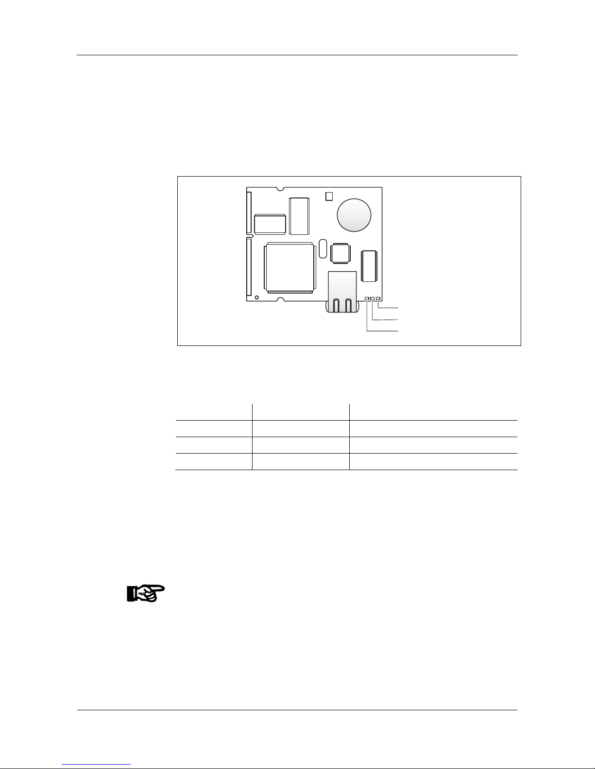
5.6.2 Ethernet connector
The BECO 500 CPU unit is equipped with a high-performance Ethernet interface,
which fulfills the IEEE 802.3u 10/100 Mbps CSMA/CD standard.
Connection takes place by patch cable 1:1 via Onboard-RJ-45 socket.
Three LEDs are located on the right hand side of the Ethernet RJ-45 connection.
Data
Link
1
0 / 100
Mbit
Fig. 15: Ethernet LED
Meaning of the light-emitting diodes
Off Lights up
Data
No data Data transmission
Link
No link Physical connection to network exists
10/100 MBit
10 MBit 100 MBit
5.6.3 Optional serial interface or modem
Clamp assignment for the serial interface depends on which optional interface is
equipped.
The clamps for the serial interface are numbered in ascending order from the
bottom up.
The optional interface is plugged on the BEX101 mother board and secured with a
screw.
NOTICE!
The settings for the respective optional interface must be adapted in the BECO500
Service Module.

User Manual B-Net 93 60 Mounting and installation
01/2006 © Kaba Benzing GmbH 29
5.6.4 Analog modem
Fig. 16: Analog modem front view and rear view
Terminal assignment BEX101
Terminal Specification Function (from the terminal)
6 Earth Line for earth key
(Used with older telephone systems to occupy an
exchange line). Not required with modern PBX
systems (e.g. occupy exchange line with number ”0“).
5 - Not used
4 A1 Series-connected telephone “A”
Is detached as soon as the modem occupies the line
3 A Incoming line (exchange / PBX) “A”
2 B1 Series-connected telephone “B”
Is detached as soon as the modem occupies the line
1 B Incoming line (exchange / PBX) “B”
Remark
A series-connected telephone is disconnected as soon as the modem occupies the
line!
Pin assignment TAE (telephone jack)
Connection TAE Assignment Color Clamp BEX101
1 A Green 3
2 B Yellow 1
3 n.c.
− −
4 Earth Gray/pink 6
5 B1 Brown 2
6 A1 White 4
F
1
2
3
4
5
6
Pin assignment RJ45 (analog)
Connection
RJ45
Assignment Color Clamp BEX101
1 n.c.
− −
2 n.c. Brown
−
3 A1 White 4
4 A Green 3
5 B Yellow 1
6 B1 Gray 2
7 Earth Pink 6
8 n.c.
− −
1
8

Mounting and installation User Manual B-Net 93 60
30 © Kaba Benzing GmbH 01/2006
5.6.5 ISDN modem
Fig. 17: ISDN modem front view and rear view
Terminal assignment BEX101
Terminal Assignment Function
6 - not used
5 - not used
4 STA / TX+ Transmitting l ine TX+
3 SRA / RX+ Receiving line RX+
2 STB / TX- Transmitting line TX1 SRB / RX- Receiving line RX-
Pin assignment RJ45 (ISDN)
Connection
RJ45
Specification Color Clamp BEX 101
1 n.c.
− −
2 n.c. Brown
−
3 STA / TX+ White 4
4 SRA / RX+ Green 3
5 SRB / RX- Yellow 1
6 STB / TX- Gray 2
7 n.c. Pink
−
8 n.c.
− −
1
8
Remark
Modem configuration can be adapted via the BECO500 Service Module, refer to
chapter
7.3.7.8.

User Manual B-Net 93 60 Mounting and installation
01/2006 © Kaba Benzing GmbH 31
5.6.6 RS485 interface (BEX302)
Remark
The RS485 interface can either be used as 2- or 4-wire partyline to the host or as
2-wire sub-partyline for the connection of subterminals.
Fig. 18: BEX302 front view and rear view
Jumper position:
2-wire
4PLI
4-wire
4PLI
4PLI
Fig. 19: BEX302 jumper assignment
4-wire partyline to host (recommended)
Clamp
BEX 101
Specification Function (from the termi n al) PIN assignment
RJ -45 connector
6 GND Signal ground Shield
5 A TxD A-line Transmit 4-wire 6
4 B TxD B-line Transmit 4-wire 3
3 A RxD A-line Receive 4-wire 2
2 B RxD B-line Receive 4-wire 1
1 C Potential compensation (C) 7+8
2-wire partyline to host
Clamp
BEX 101
Specification Function (from the termi n al) PIN assignment
RJ -45 connector
6 GND Signal ground Shield
5
4
3 A RxD A-line 2-wire 2
2 B RxD B-line 2-wire 1
1 C Potential compensation (C) 7+8

Mounting and installation User Manual B-Net 93 60
32 © Kaba Benzing GmbH 01/2006
Connection of subterminals
The subterminals are connected via a 2-wire sub-partyline. The sub-partyline is an
RS485 bus operated in 2 wire technology. It can be designed in star-shape or as
partyline.
A
TX/RX-
A
BB
TX/RX+
D
R
CC
D
R
Control unit Subterminal
Fig. 20: Concept of 2-wire sub-partyline
Only two lines are required which are triggered half-duplex. The two bus lines are
specified with A and B, whereas A does not invert the signal and B inverts the
signal.
Reference potential for the interface forms the additional C line.
For the cable joints, the standard category 5 cable with 4 wire pairs, AWG 24-22
(0.5-0.65 wire-Ø), and the structure S-UTP (Screened Unshielded Twisted Pair)
must be used (CAT.5).
This cable has a foil shield (screened). The wire pairs are not individually shielded
against each other (unshielded). Always two wires which match in colors are
twisted with each other (Twisted Pair). In accordance with EN 50 173 all 8 wires
must be wired end-to-end. This way consistently structured cabling is available.
Not wiring unused wires contradicts the principles of a structured cabling.
2-wire sub-partyline
Terminal
BEX101
Specification Function (from the termi n al) PIN assignment
RJ 45 connector
6 GND Signal ground Shield
5
4
3 B TX/RX- B-line 2-wire 2
2 A TR/RX+ A-line 2-wire 1
1 C Potential com pensation (C) 7+8
The shielding of the data line is generally connected on both sides.

User Manual B-Net 93 60 Mounting and installation
01/2006 © Kaba Benzing GmbH 33
Remark
The specifications of signal lines A and B have been swapped with Kaba Benzing’s
Bedas and Bedanet devices.
Specifications of signal lines with newer devices as well as with the B-Net Series
are correct.
The various subterminals must therefore be wired according to the following
overview.
Subterminal Manufacturer B-Net 93 60 Subterminal
Bedas 91 05 Kaba Benzing
Bedas 91 10 Kaba Benzing
A
B
Bedas 91 20 Kaba Benzing
Bedas 91 40 Kaba Benzing
B
A
Bedanet 91 04 Kaba Benzing
Bedanet 91 05 Kaba Benzing
Bedanet 91 20 Kaba Benzing
Subterminal Manufacturer B-Net 93 60 Subterminal
Bedanet 90 20 Kaba Benzing
LR-100 Kaba AG
A
A
LS -110 Kaba AG
B
B

Mounting and installation User Manual B-Net 93 60
34 © Kaba Benzing GmbH 01/2006
5.6.7 RS232 interface (BEX301)
The RS232 interface (V24) is used to connect a second reader.
Fig. 21: BEX301 front view and rear view
5.6.8 RJ-45 Connection for second reader
The second serial reader can be connected to this connector. In this case the
optional interface BEX301 RS232 must be equipped.
Assignment
Pin Assignment
1 VCC 5 V DC; max. 200 mA
2 3 GND
4 5 TxD
6 7 8 -
18
Remarks
• Communication parameters: 9600, 8, N, 1.
• The serial interface works with RS-232 levels, not with TTL.
• Hardware handshake is not supported.
• No transmit delay of scanner data.

User Manual B-Net 93 60 Mounting and installation
01/2006 © Kaba Benzing GmbH 35
5.6.9 Digital inputs
Terminal Assignment
GND
GND
Common ground
for E1 to E4
Open / High Ground / Low
E4 Alarm Sabotage alarm Idle state
E3 Block te rminal Idle state Terminal blocks
E2 Door-opener push
button
Idle state Door opens
E1 Doo r-frame contact Door open Idle state
The inputs can be easily controlled with a simple switch or relay contact. The
corresponding input is connected to common ground. An open input is recognized
as “high” due to the internal pull-up resistor. Ground potential equals “low.”
The input circuit also allows the control via connected potential in the following
ranges:
Input voltage 30 V DC max.; min – 30 V DC
Level
High = + 2.6 V to + 30 V or open
Low = - 30 V to + 2.3 V
Principle
Door-frame contact
Door-opener push button or door-handle
contact
Block terminal
Alarm
E1
E2
E3
E4
G
ND
Fig. 22: Concept of digital inputs
NOTICE!
Do not remove the wire links at the E1 and E4 inputs if these inputs are not used!
Mounting and installation User Manual B-Net 93 60
36 © Kaba Benzing GmbH 01/2006
5.6.10 Relay outputs
Assignment
Relay 2 Door opener 2 (OUT)
Relay 1 Door opener 1 (IN)
NOTICE!
The relays are designed for 30 V AC / DC and 2 A maximum.
For device safety reasons 115 / 230 V may not be switched with this relay.
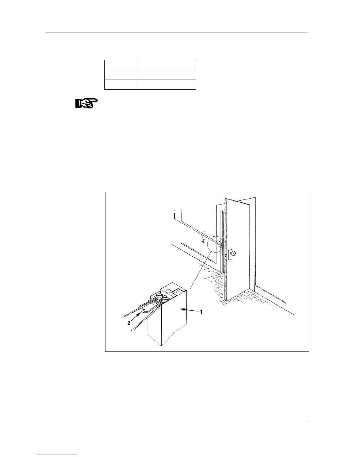
Door opener
For door openers that are supplied with DC voltage, the included diode
(a freewheeling diode) must be connected parallel to the door opener to suppress
interference. In doing so, make sure that the diode is connected in reverse-bias
direction. When using an AC voltage power supply, the included varistor type
S10K30 must be connected parallelly.
The diode or varistor must be connected directly to the door opener and must not
be fitted in the terminal.
Fig. 23: Door opener
1 Door opener
2 Freewheeling diode or varistor

User Manual B-Net 93 60 Mounting and installation
01/2006 © Kaba Benzing GmbH 37
5.6.11 Input 24 V
The supply voltage for the terminal is connected to this clamp.
The supply of the terminal can take place via an integrated SV9001 (optional) or
via an external power supply e.g., SV900 or SV905.
Rated voltage: 24 V AC/DC
Voltage range: 12 -27 V AC
16 -32 V DC
Frequency: 50 -60 Hz
Power consumption: 25 W max.
NOTICE!
Please make sure that the input voltage range during maximum load is observed.
Important for devices with host connection via RS485!
If several terminals are supplied with the same DC voltage, it must be considered
that the polarity at the input terminals is consistent (preferably Plus at bottom).

Mounting and installation User Manual B-Net 93 60
38 © Kaba Benzing GmbH 01/2006
5.6.12 SV9001 power supply
The terminal may be equipped with the internal power supply SV9001.
+ -
I 0
NL1
24 V DC
12 V DC
6 V DC
1
2
3
4
5
Fig. 24: SV9001 power supply
1 Jumper to set door-opener voltage
2 24 V AC operating voltage for the terminal
3 Operating voltage for door-opener
24 V DC, 12 V DC or 6 V DC; depending on jumper position
max. 4 VA 100% on-time, max. 8 VA 10% on-time
4 Power input 115 V AC max. 140 mA (115 V version)
Power input 230 V AC max. 70 mA (230 V version)
5 Mains switch
NOTICE!
With the terminal’s 24 V AC operating voltage (terminal 2), NO additional dooropener may be supplied.

User Manual B-Net 93 60 Mounting and installation
01/2006 © Kaba Benzing GmbH 39
5.7 Hardware options
5.7.1 BEX400 memory expansion unit
The BECO500 CPU unit is equipped with 1 MB internal SRAM. With the BEX400
memory expansion unit the memory space for data can be expanded with 4 MB to
a total of 5 MB.
The SODIMM socket for the memory module is located on the BEX100 board.
NOTICE!
The BEX400 memory expansion unit is SRAM. By using DRAM or S-DRAM PC
memory modules, the BECO500 CPU unit can be damaged or destroyed.
During mounting and demounting of the BEX400 memory expansion unit, the
ESD protective measures must be considered.
Fig. 25: BEX400 Memory Expansion Unit
1 BEX101 board 4 BECO500 CPU unit
2 BEX400 memory expansion unit 5 Buffer battery
3 SODIMM socket
NOTICE!
The SRAM sector serves as main memory with file system.
Removing the BEX400 memory expansion unit or the buffer battery on the
BECO500 CPU unit in off-circuit state, leads to data and formatting loss.
After the memory extension has been mounted, the SRAM area must be newly
formatted. This takes place automatically when performing a cold start. Refer to
chapter
6.3.3.

Mounting and installation User Manual B-Net 93 60
40 © Kaba Benzing GmbH 01/2006
5.7.2 Uninterruptible power supply BEX500
The terminal may optionally be equipped with the uninterruptible power supply
(UPS) BEX500. The UPS is integrated right next to the serial reader in the housing
front and is connected to the BEX101 mother board.
Fig. 26: BEX500 UPS
5.7.2.1 Technical data BEX500 UPS
Input voltage: 24 V according to rectifier level
Output voltage: 5 V
Performance: approx. 14 Wh
Accumulator type: 2 x Panasonic CGA103450, Lithium-ion or equivalent
Accumulator power: Voltage 8.8 to 6.0 V average 7.6 V
Accumulator
capacity:
1800 mAh typical

User Manual B-Net 93 60 Mounting and installation
01/2006 © Kaba Benzing GmbH 41
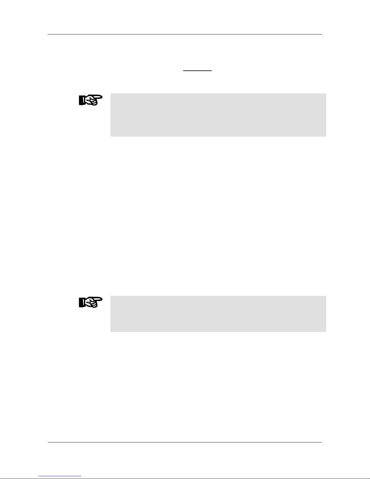
5.7.2.2 Switch for emergency power operation
A micro switch is located in the upper left corner of the BEX500 printed circuit
board for activation of the emergency power operation. During transport and
storage, the emergency power operation must be deactivated. Charging mode is
also possible.
Remark
The micro switch must be operated with a pointed object, e.g. pen, small
screwdriver, or tweezers.
1
2
ONO
FF
3
Fig. 27: BEX500 UPS switch for emergency power operation and LEDs.
1 Switch for emergency power operation
Meaning
2 LED red Lights up = Charging
Blinks = Error
3 LED green Lights up = Accumulator > 90% charged

Set-up User Manual B-Net 93 60
42 © Kaba Benzing GmbH 01/2006
6 Set-up
6.1 Set-up process
Set-up takes place as follows:
• Link service PC with the terminal.
• Start device in service mode.
Refer to chapter
6.3.4
• Call up BECO500 service module via http browser.
Refer to chapter
7.2
• Log in with user name: localuser, Password: Bedanet
• Set network parameter
Hardware Settings / Ethernet Communication Parameter
Refer to chapter
7.3.7.1
• Enter the group and device address (GID/DID) of BECO500
Hardware Settings / Hostline Parameters
Please refer to chapter
7.3.7.4
• Restart device in application mode
System Monitoring and Maintenance / Restart or switch device off/on.
Refer to chapter
7.3.6.10
• Loading of specific parameters and master records from host
Please refer to the Manual of the used application.
Remark
The BECO500 Service Module is described in detail in chapter
7.

User Manual B-Net 93 60 Set-up
01/2006 © Kaba Benzing GmbH 43
6.2 Set-up of optional hardware
NOTICE!
Before the modification of devices already in operation, save parameters and
master records.
After modification, the changed parameters must be sent from the communication
software to the device.
Remark regarding the use of serial interfaces (Serial Line)
Each serial interface can only be assigned to one function (Reader, Host Line or
Sub Line). It must be considered that the respective interface is deactivated in the
other service functions.
6.2.1 Second reader (external reader, e.g. CCD hand sc anner)
Hardware requirements:
• The terminal must be equipped with option BEX301 (interface RS232).
• The second reader must be connected to the RJ-45 connector on the
BEX101 mother board, refer to chapter
5.6.8
Settings in the service module:
• Hardware Settings/Serial Line Communication Parameter,
refer to chapter
7.3.7.2
• COM1: Enabled
• Bits per second: 9600
• Data bits: 8
• Parity NONE
• Stop bits: 1
• Hardware Settings/Reader, refer to chapter
7.3.7.3
• Reader 2: Enabled
• Interface: COM1
• Type: Barcode
• Hardware Settings/Sub Line Parameter,
refer to chapter
7.3.7.5
• Sub line: Disabled
6.2.2 Replacing a reader module with other reader type
Settings in the service module:
• Hardware Settings/Reader, refer to chapter
7.3.7.3
• Reader 1: Enabled
• Interface: COM2
• Type: (new reader type)

Set-up User Manual B-Net 93 60
44 © Kaba Benzing GmbH 01/2006
6.2.3 Host connection via partyline
Hardware requirements:
• The terminal must be equipped with option BEX302 (interface RS485).
• The host partyline must be connected at the BEX101, please refer to chapter
5.6.6
Settings in the service module:
• Hardware Settings/Host Line, refer to chapter
7.3.7.4.
• Host Line: Enabled
• Interface: COM1
• Group ID: (GID)
• Device ID: (DID)
• Hardware settings/serial line communication parameter,
please refer to chapter
7.3.7.2.
• COM 1: Enabled
• Bits per second: 9600
• Data bits: 7
• Parity EVEN
• Stop bits: 1
6.2.4 Host connection via modem
Hardware requirements:
• The terminal must be equipped with an optional internal analog modem or
ISDN modem.
Settings in the service module:
• Hardware Settings/Host Line, refer to chapter
7.3.7.4.
• Host Line: Enabled
• Interface: COM1
• Group ID: (GID)
• Device ID: (DID)
• Hardware settings/serial line communication parameter,
please refer to chapter
7.3.7.2.
• COM 1: Enabled
• Bits per second: 9600
• Data bits: 7
• Parity EVEN
• Stop bits: 1
• Initialize modem; refer to chapter
7.3.7.8

User Manual B-Net 93 60 Set-up
01/2006 © Kaba Benzing GmbH 45
6.2.5 Subterminal
Hardware requirements:
• The terminal must be equipped with option BEX302 (interface RS485).
• The subterminals must be connected at the BEX101 mother board, please
refer to chapter
5.6.6
Other requirement:
• To support subterminals a corresponding license key is required; refer to
chapter
7.3.6.8.
Settings in the service module:
• Hardware Settings/SubLine, refer to chapter
7.3.7.5.
• Sub line 1: Enabled
• Interface: COM1
• Hardware settings/serial line communication parameter,
please refer to chapter
7.3.7.2.
• COM 1: Enabled
• Bits per second: 19200
• Data bits: 7
• Parity EVEN
• Stop bits: 1
Set-up User Manual B-Net 93 60
46 © Kaba Benzing GmbH 01/2006
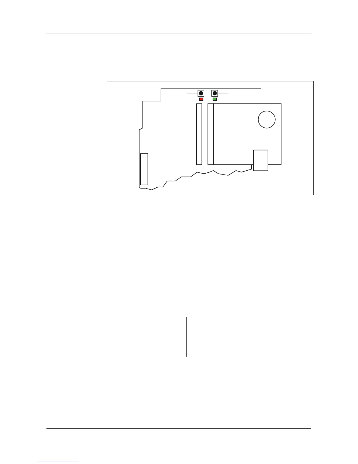
6.3 Start options
6.3.1 Function of buttons and LEDs
BEX101
BECO500
1
2
3
4
Fig. 28: Buttons and light emitting diodes on BEX101
1 Cold start button
2 Service button
3 LED red
4 LED green
The buttons allow for a system start with execution of the following start options:
• Cold start of the application, please refer to chapter
6.3.3
• Start of service mode, please refer to chapter
6.3.4
• Start of service mode and set back to default IP, please refer to chapter
6.3.5
The light emitting diodes signal if the respective start option has been executed.
LED red (3) LED green (4) Meaning
Lights up Off Application runs
Off Lights up Service module running
Blinks Off Application or service module not available
User Manual B-Net 93 60 Set-up
01/2006 © Kaba Benzing GmbH 47
6.3.2 Start of application
The application is started, if neither one of the buttons is pressed during switch on.
6.3.3 Cold start of application
NOTICE!
When performing a cold start, parameters are reset to their default values. Master
records and booking records are deleted.
Network settings, group and device address, as well as the INI file entries remain
unchanged.
How to perform a cold start:
• Turn off the device
• Push and hold the cold start button
• Turn on device
• Release cold start button after approx. 5 seconds
6.3.4 Start of service mode
Performing a system start in service mode:
• Turn off the device
• Push and hold the service button
• Turn on device
• Release service button after approx. 5 seconds
6.3.5 Start of service mode and reset to default IP
This start option makes a start of the service mode possible with concurrent reset
of the terminal IP address to default IP 123.0.0.2.
NOTICE!
A possibly already set IP address is overwritten, DHCP is disabled.
All other settings like host IP address, UPD port number and GID/DID remain
unchanged.
Execution:
• Turn off the device
• Push and hold the service button
• Turn on device
• Release service button after approx. 12 seconds

BECO service module User Manual B-Net 93 60
48 © Kaba Benzing GmbH 01/2006
7 BECO service module
The BECO (Benzing Embedded COre) CPU unit is used inside terminals and
control units of Kaba Benzing’s Bedanet and B-Net Series.
The BECO Service Module provides the functions that are required for setup,
maintenance, and diagnosis. It is consistently used for all devices where the BECO
is deployed.
The Service Module is an independent and from the actual terminal software
autonomous application that runs on the BECO alternatively to the device software.
The Service Module is there stored as “service.obf" or as "service.lzo." The file with
the file extension “Izo“ has a packed file format. The unpacked file format has the
extension “obf.“
The existing Ethernet connection is used as an interface. Communication takes
place via an arbitrary system (service PC) within the network. However, the service
PC can also be connected directly with the BECO. An HTTP browser with Java VM
support must be installed on the service PC.
An http server and an FTP server runs in service mode. Data for the display of
statistical information is stored on the BECO as HTML files. Data for the display of
dynamic information is generated by the service module in Servlets / Active Server
Pages (ASP) and then sent to the browser as HTML.
User dialogs for the modification of settings (e.g., date, addresses) are carried out
in Java applets.
The BECO service module allows for the following functions
• Menu-driven service functions via dialog browser
• FTP access
• Local setting of communication parameters
7.1 Start of service module
NOTICE!
The device must be started in service mode in order to utilize the functions of the
Service Module. Refer to chapter
6.3.4.
The Service Module is not available in the normal application mode.
Depending on the application active at the moment, the service mode can also be
started via B-COMM or per FTP with a respective control record.
For further details please refer to the application’s User Manual.

User Manual B-Net 93 60 BECO service module
01/2006 © Kaba Benzing GmbH 49
7.2 Access to the service module
Access to the FTP server and the HTML server of the Service Module takes place
via the BECO’s Ethernet connection.
7.2.1 First access
The default IP address 123.0.0.2 is preset on the BECO
• with ex factory delivery
• after the start of the service mode with simultaneous setting of the default IP
address. For this purpose, press and hold the service button for at least 12
seconds.
(Details about the individual start options are explained in chapter
6.3).
The network setting in the service PC must be configured accordingly, e.g. IP
address 123.0.0.1. The Service PC must be in the same network segment.
For initial startup, the service PC is connected directly to the BECO via an Ethernet
cross over cable (crossed RJ-45 cable).
7.2.2 Access after executed ne twork parameter setting
After startup, the BECO’s service module can be called up via the entered IP
address.
Remark
A newly set IP address will be active after the device has been rebooted.
7.3 Service functions
The communication with the menu-driven service functions of the BECO Service
Module takes place via an HTTP browser.
7.3.1 Demands on the HTTP browser
User dialogs for the modification of settings (e.g., date, addresses) are carried out
in Java applets.
The HTTP browser used must therefore support Java applets.
An installed and activated Sun JRE version as of 1.4.2_03 is required.
7.3.2 Call of service functions
As soon as the BECO is physically connected with the service PC, the service
functions can be accessed with the help of the HTTP browser. For this purpose
simply enter the BECO’s IP address (default 123.0.0.2).
Remark
Please consider, that with an active IP address filter the proxy server must be
avoided where applicable.

BECO service module User Manual B-Net 93 60
50 © Kaba Benzing GmbH 01/2006
7.3.3 Log-in
If the BECO is addressed via the browser, it answers with a login mask. Here, user
name and password are requested that control the access to the individual
functions.
Fig. 29: Log-in mask
Enter user name and password. Then press the “Submit” button.
Users
The following users are already created by default:
User name Password Access rights Use
localuser Bedanet
limited Set-up
root Bedanet
unlimited Expert mode
 Loading...