

Kaba 7102 series, 7108 series, SIMPLEX 7102 SERIES, SIMPLEX 7108 SERIES Installation Instructions Manual

7 1 0 2
7 1 0 8
SERIES
Installation Instructions

Important: Please keep these instructions. The combination of this lock has
been factory preset: 2 and 4 pressed together, then 3.
WARNING
For your own safety, you must change the combination at the time of
installation.
PLEASE READ AND FOLLOW ALL DIRECTIONS CAREFULLY
Since every installation is unique, carefully check windows, frame, door, etc. to
ensure that the recommended procedures will not cause damage. KABA is not
responsible for any damage caused by installation.
Tools Required
•
1
⁄4" (6 mm) Drill Bit
• 1" (25 mm) Wood Chisel
•
3
⁄4" (19 mm) Hole Saw
• Phillips-head Screwdriver
• 1" (25 mm) Drill Bit or Hole Saw
• 1
5
⁄8" (41 mm) Hole Saw
Caution: Wear safety glasses when preparing door.
• 2 Pairs of Pliers
• Hacksaw
• Hammer
• Center Punch
• Drill (variable speed recommended)

1
For technical assistance please call
1-800-849-TECH (8324) or 336-725-1331
Table of Contents
Checklist . . . . . . . . . . . . . . . . . . . . . . . . . . . . . . . . . . . . . . . . . . . . . . . . . . . . . . . . . . . . . . . . .2
Determining the Hand of Your Door . . . . . . . . . . . . . . . . . . . . . . . . . . . . . . . . . . . . . . . . .2
A. Determining the Lock Location . . . . . . . . . . . . . . . . . . . . . . . . . . . . . . . . . . . . . . . . . . . . .3
B. Marking the Door . . . . . . . . . . . . . . . . . . . . . . . . . . . . . . . . . . . . . . . . . . . . . . . . . . . . . . . . . .3
C. Drilling Holes in the Door . . . . . . . . . . . . . . . . . . . . . . . . . . . . . . . . . . . . . . . . . . . . . . . . . .4
D. Making the Bolt Face Plate Cutout . . . . . . . . . . . . . . . . . . . . . . . . . . . . . . . . . . . . . . . . . .4
E. Installing the Bolt . . . . . . . . . . . . . . . . . . . . . . . . . . . . . . . . . . . . . . . . . . . . . . . . . . . . . . . . .5
F. Adjusting the Lock . . . . . . . . . . . . . . . . . . . . . . . . . . . . . . . . . . . . . . . . . . . . . . . . . . . . . . . .5
G. Installing the Lock . . . . . . . . . . . . . . . . . . . . . . . . . . . . . . . . . . . . . . . . . . . . . . . . . . . . . . . . .6
H. Checking the Locks Operation . . . . . . . . . . . . . . . . . . . . . . . . . . . . . . . . . . . . . . . . . . . . . .7
I. Installing the Strike . . . . . . . . . . . . . . . . . . . . . . . . . . . . . . . . . . . . . . . . . . . . . . . . . . . . . . . .8
J. Setting a New Combination . . . . . . . . . . . . . . . . . . . . . . . . . . . . . . . . . . . . . . . . . . . . . . . . .8
K. Instructions for Resetting Unknown Combinations . . . . . . . . . . . . . . . . . . . . . . . . . . . .10
L. Troubleshooting . . . . . . . . . . . . . . . . . . . . . . . . . . . . . . . . . . . . . . . . . . . . . . . . . . . . . . . . . .12
Templates (Center of Manual)

2
CHECKLIST
Use this checklist to make sure that
everything has been included.
A - Front Lock
C - Dead Bolt 7102 (23⁄4") or
7108 (2
3
⁄8") (model specific)
D - Inside Thumbturn Assembly
E - Inside Combination Change Assembly
Screw Pack:
F - Strike Plate
G - 4 thru-bolts (3")
H - 2 (bolt) combination wood/metal screws
I - 4 combination wood/metal screws
J - 4 Thru bolts (2
3
⁄8")
K - 4 Thru bolts (2")
Templates (in center of booklet)
DETERMINE THE HAND OF YOUR DOOR
Many of the installation instructions refer to the handing of your door. The hand
of the door is determined with the door in the closed position, from the exterior
or pushbutton side of the door.
A) Right Hand Door. Door opens inward
(push). Hinged on the right side.
B) Left Hand Door. Door opens inward
(push). Hinged on the left side.
C) Right Hand Reverse Door. Door opens
outward (pull). Hinged on the right side.
D) Left Hand Reverse Door. Door opens out-
ward (pull). Hinged on the left side.
LH - Left Hand
RH - Right Hand
LHR - Left Hand Reverse
RHR - Right Hand Reverse
A
B
C
D
A
E
D
C
F
H
I
K
G
J

3
A. DETERMINING THE LOCK
LOCATION
Install the lock with the exterior thumbturn hole at
least 7" (18 cm) above your primary lockset so it is
comfortable to operate and not in the way when
you turn the door knob.
A minimum stile width of 4" (10.16 cm) is recommended for mounting (See Figure 1-1).
B. MARKING THE DOOR
NOTE: Be sure to use the correct template
(right-hand or left-hand door - 2
3
⁄8" or 23⁄4").
If the wrong template is used, you will have to
redrill the door, leaving previously drilled holes
exposed.
B-1 Carefully fold the template on 2
3
⁄8" or 23⁄4"
line (found in the center of this booklet)
(See Figure 2-1).
B-2 Tape the template securely to the outside of the
door so that all the indicated folds are properly aligned with the edge of the
door.
B-3 Use a center punch to make the marks for drilling the seven holes precisely
at the points indicated on the template. The center punch mark in the edge
of the door must be centered based on the thickness of the door.
B-4 Remove the template.
C. DRILLING HOLES IN THE DOOR
CAUTION: Positioning and drilling must be done
straight to ensure trouble free operation of the 7100
Series lockset. Improper drilling may result in excessive force being exerted on the lock which may result
in the premature wearing of its mechanical parts.
You must do C-1 first otherwise it will be
impossible to drill the
1
⁄4" (6 mm) holes.
C-1 Use a
1
⁄4" (6 mm) drill bit to drill the four holes
marked A (See Figure 3-1). Begin drilling at a
slow speed and increase the speed gradually
until the tip of the drill bit emerges from the other side of the door. Repeat
this procedure from the opposite side of the door. This technique will prevent splintering of the door or breaking the drill bit.
2-1
1-1
7"
(18 cm)
4"
(
102 mm)
3-1
1
⁄4"A
B
1" D
3
⁄4"C

4
C-2 Use a hole saw with pilot bit to make the 1
5
⁄8"
(41 mm) hole (B). Apply pressure evenly until
the circular blade cuts the first side of the door
and the tip of the pilot bit emerges through the
other side, then stop. Drill from the other side
until the 1
5
⁄8" (41 mm) hole is completed.
C-3 Repeat C-2 for the
3
⁄4" (19 mm) hole, (C).
C-4 The final 1" (25 mm) hole (D) is crossbored
through the edge of the door. Carefully bore 4"
(10 cm) deep (See Figures 3-1 and 3-2).
D. MAKING THE BOLT FACE PLATE
CUTOUT
This procedure is applicable to wood doors.
D-1 Insert the bolt into the 1" (25 mm) hole until the face plate butts up against
the door edge. Draw a line around the face plate. Remove the bolt from the
door, A (See Figure 4-1).
D-2 For doors without a beveled edge, use a sharp
1" (25 mm) wood chisel to remove approximately
1
⁄8" (3 mm) of material or enough so
the face plate is perfectly flush with the edge
of the door, B (See Figure 4-1).
D-3 For doors with a beveled edge, follow step 2
except the face plate will not be flush with the
edge of the door, but rather square to the face of the door. In order to
accomplish this, you must remove more wood from the higher edge of the
door.
E. INSTALLING THE BOLT
E-1 Right Hand Door (see template)
a. Insert the bolt, with the arrow pointing up,
into the 1" (25 mm) hole (See Figure 5-1).
b. Secure the bolt face plate to the door with
the two Phillips-head screws provided.
3-2
5-1
4-1
B
B
4" (10 cm)
A
3-1
1
⁄4"A
B
1" D
3
⁄4"C

5
E-2 Left Hand Door (see template)
a. Insert the bolt, with the arrow pointing down,
into the 1" (25 mm) hole (See Figure 5-2).
b. Secure the bolt face plate to the door with
the two Phillips-head screws provided.
F. ADJUSTING THE LOCK
The lock has been pre-assembled to
accommodate doors up to 2
1
⁄4" (57 mm) thick.
If your door is 1
3
⁄8" to 2 " (35 mm to 51 mm) thick,
you must shorten both tailpieces X and Y (See
Figure 6-1).
F-1. Shorten the combination change tailpiece X
according to your door thickness. Tailpiece X
has been premarked for various door thicknesses for accuracy and convenience (See
Figure 6-1).
a. After determining the breakoff point, hold
the tailpiece firmly with a pair of pliers on
the lock side of the tailpiece, just beside
the desired break line (See Figure 6-2).
b. With a second pair of pliers, grip the
tailpiece at the other side of the line
and bend it up and down until it breaks
(See Figure 6-2).
F-2. While holding the lockset firmly against the outside surface of the door,
(See Figure 6-1), mark tailpiece Y at the point where it extends
1
⁄2" -5⁄8" beyond the interior surface of the door.
a. After determining the breakoff point, hold the tailpiece firmly with a pair
of pliers on the lock side of the tailpiece, just beside the desired break
line (See Figure 6-2).
b. With a second pair of pliers, grip the tailpiece at the other side of the
line and bend it up and down until it breaks (See Figure 6-2).
5-2
6-2
1
X
Y
2
6-1

6
G. INSTALLING THE LOCK
• For 13⁄8" - 11⁄2" (35 mm - 38 mm) thick doors, use the 23⁄8" (44 mm) thru bolts.
• For 1
1
⁄2" - 2" (38 mm - 51 mm) thick doors, use the 23⁄8" (44 mm) thru bolts.
• For 2" - 2
1
⁄4" (51 mm - 57 mm) thick doors, use the 3" (76 mm) thru bolts.
G-1. With the bolt extended in the locked position,
mount the lock from the outside of the door.
Insert the tailpiece Y into the vertical cutout of
the bolt assembly and the tailpiece X into the
3
⁄4” (19 mm) hole (See Figure 7-1).
G-2. Hold the exterior lock assembly firmly against
the door. Try the factory-set combination.
Press buttons #2 and #4 together, release,
press button #3, and release. A distinctive
click must be felt to indicate that the button
has been correctly depressed. Turn the outside thumbturn to the right (clockwise) to the
stop position and release (the bolt should be
fully retracted). If not, turn the thumbturn to
the left (counterclockwise) to the stop position and repeat Step G-2.
G-3 While holding the lock firmly against the out-
side surface of the door with one hand, use
the other to mount the inside thumbturn
assembly to the interior side of the door with
two thru-bolts finger tight (See Figure 7-2).
Make sure that tailpiece Y is engaged into the
vertical cutout of the inside thumbturn assembly.
G-4 Insert tailpiece X into the horizontal slot of the
combination change assembly. It may be necessary to use a screwdriver to align tailpiece X
with the combination change assembly (See
Figure 7-3). Once aligned, secure with two
thru-bolts, but do not tighten (See Figure 7-4).
Note: The inside thumbturn is shown in a vertical position to show the two
thru-bolts. It may be assembled either vertically or horizontally.
IMPORTANT: Tailpiece X must be inserted in the horizontal slot in order to
change your combination.
G-5 Make sure that both assemblies are correctly centered over the holes.
Tighten the thru-bolts evenly. Uneven tension could cause a malfunction
or damage to the lock.
7-1
7-4
7-3
7-2
X
X
Y
Y

7
H. CHECKING THE LOCK’S OPERATION
IMPORTANT: The following steps MUST be performed while the DOOR IS OPEN.
Note: Turning the outside thumbturn to the left (counterclockwise) to the stop
position and releasing extends the bolt to the locked position. To retract the
bolt from the outside, depress the buttons of your preset combination, then
turn the thumbturn to the right (clockwise) to the stop position.
H-1 Turn the outside thumbturn to the left (coun-
terclockwise) until it stops, then release it (See
Figure 8-1).
H-2 Press the preset factory combination (2 and 4
pressed together, release, then 3, and release)
(See Figure 8-2). A distinctive click must be
felt to indicate that the buttons have been correctly depressed.
H-3 Turn the outside thumbturn to the right (clock-
wise) until it stops; the bolt should fully retract
(See Figure 8-3). If the bolt does not retract,
turn the thumbturn to the left (counterclockwise) until it stops. This will clear previously
depressed buttons. Release it and repeat Steps
H-2 and H-3.
H-4 Release the outside thumbturn; the bolt will
stay in the retracted position.
H-5 Turn the inside thumbturn A to the stop posi-
tion; the bolt will extend to its locked position
(See Figure 8-4).
H-6 If the bolt does not retract or extend fully,
loosen the two thru-bolts of the inside thumbturn assembly A (See Figure 8-4). Move the
inside thumbturn assembly upward or downward to properly center the inside thumbturn
assembly with the tailpiece, then tighten the
thru-bolts, and repeat Steps H-1 to H-5.
H-7 If the bolt still does not fully retract or extend
after repeating Step H-6, loosen the two thrubolts of the inside thumbturn assembly A and combination change
assembly B (See Figure 8-4). Move the lock upward or downward to
properly align both tailpieces of the inside thumbturn assembly and
combination change assembly. Tighten the four thru-bolts and repeat
Steps H-1 to H-5 to ensure proper operation.
8-1
8-2
8-3
8-4
B
A

KABA SIMPLEX
®
LIMITED WARRANTY
Kaba Access Control warrants this product to be free from defects in material
and workmanship under normal use and service for a period of one (1) year.
Kaba Access Control will repair or replace, at our discretion, locks found by
Kaba Access Control analysis to be defective during this period. Our only liability, whether in tort or in contract, under this warranty is to repair or replace
products that are returned to Kaba Access Control within the one (1) year warranty period.
This warranty is in lieu of and not in addition to any other warranty or condition, express or implied, including without limitation merchantability, fitness for
purpose or absence of latent defects.
ATTENTION: This warranty does not cover problems arising out of improper
installation, neglect or misuse. All warranties implied or written will be null and
void if the lock is not installed properly and /or if any supplied component part
is substituted with a foreign part. If the lock is used with a wall bumper, the
warranty is null and void. If a doorstop is required, we recommend the use of a
floor secured stop.
The environment and conditions of use determine the life of finishes
on Kaba Access Control products. Finishes on Kaba Access Control products
are subject to change due to wear and environmental corrosion. Kaba Access
Control cannot be held responsible for the deterioration of finishes.
Authorization to Return Goods
Returned merchandise will not be accepted without prior approval. Approvals
and Returned Goods Authorization Numbers (RGA Numbers) are available
through our Customer Service department in Winston-Salem, NC
(800) 849-8324. The serial number of a lock is required to obtain this RGA
Number. The issuance of an RGA does not imply that a credit or replacement
will be issued.
The RGA number must be included on the address label when material
is returned to the factory. All component parts including latches and strikes
(even if not inoperative) must be included in the package with return. All
merchandise must be returned prepaid and properly packaged to the address
indicated.

1
3
/4"
(44 mm)
1
3
/8"
(35 mm)
2"
(51 mm)
11/2 "
(38 mm)
CAUTION
Apply template and drill
from the outside but
compensate for door
bevel if any
Deadbolt cutout
2
1
/4"
(57 mm)
1" dia.
(25 mm)
4" deep
(10 cm)
1
5
/8
"
(41 mm)
*backset
1"
(25 mm)
2
1
/4"
(58 mm)
Bore
1" (25 mm) dia.
latch hole
MARK
ACCURATELY
BORE
STRAIGHT
LEFT HAND DOOR
7102 / 7108
TEMPLATE
NOTE: Lock will accomodate doors
1
3
/8" (35 mm) to 21/4" (57 mm) thick.
Suitable reinforcement shall be provided
by the hollow metal door manufacturer
to prevent collapsing of door. When
door silencers are to be installed,
proper allowances must be made for
strike location.
Edge of door for 2
3
/4" (70 mm) Backset
* For both 2
3
/8" (60mm) and 2
3
/4" (70mm) backsets
IMPORTANT
Use this as edge of
door when boring hole
Mark center of
door thickness

1
3
/4"
(44 mm)
1
3
/8"
(35 mm)
2"
(51 mm)
11/2 "
(38 mm)
CAUTION
Apply template and drill
from the outside but
compensate for door
bevel if any
Deadbolt cutout
2
1
/4"
(57 mm)
1" dia.
(25 mm)
4" deep
(10 cm)
1
5
/8
"
(41 mm)
1"
(25 mm)
2
1
/4"
(58 mm)
Bore
1" (25 mm) dia.
latch hole
*
MARK
ACCURATELY
BORE
STRAIGHT
RIGHT HAND DOOR
7102 / 7108
TEMPLATE
NOTE: Lock will accomodate doors
1
3
/8" (35 mm) to 21/4" (57 mm) thick.
Suitable reinforcement shall be provided
by the hollow metal door manufacturer
to prevent collapsing of door. When
door silencers are to be installed,
proper allowances must be made for
strike location.
*
Edge of door for 2
3
/4" (70 mm) Backset
*backset
* For both 2
3
/8" (60mm) and 2
3
/4" (70mm) backsets
IMPORTANT
Use this as edge of
door when boring hole
Mark center of
door thickness

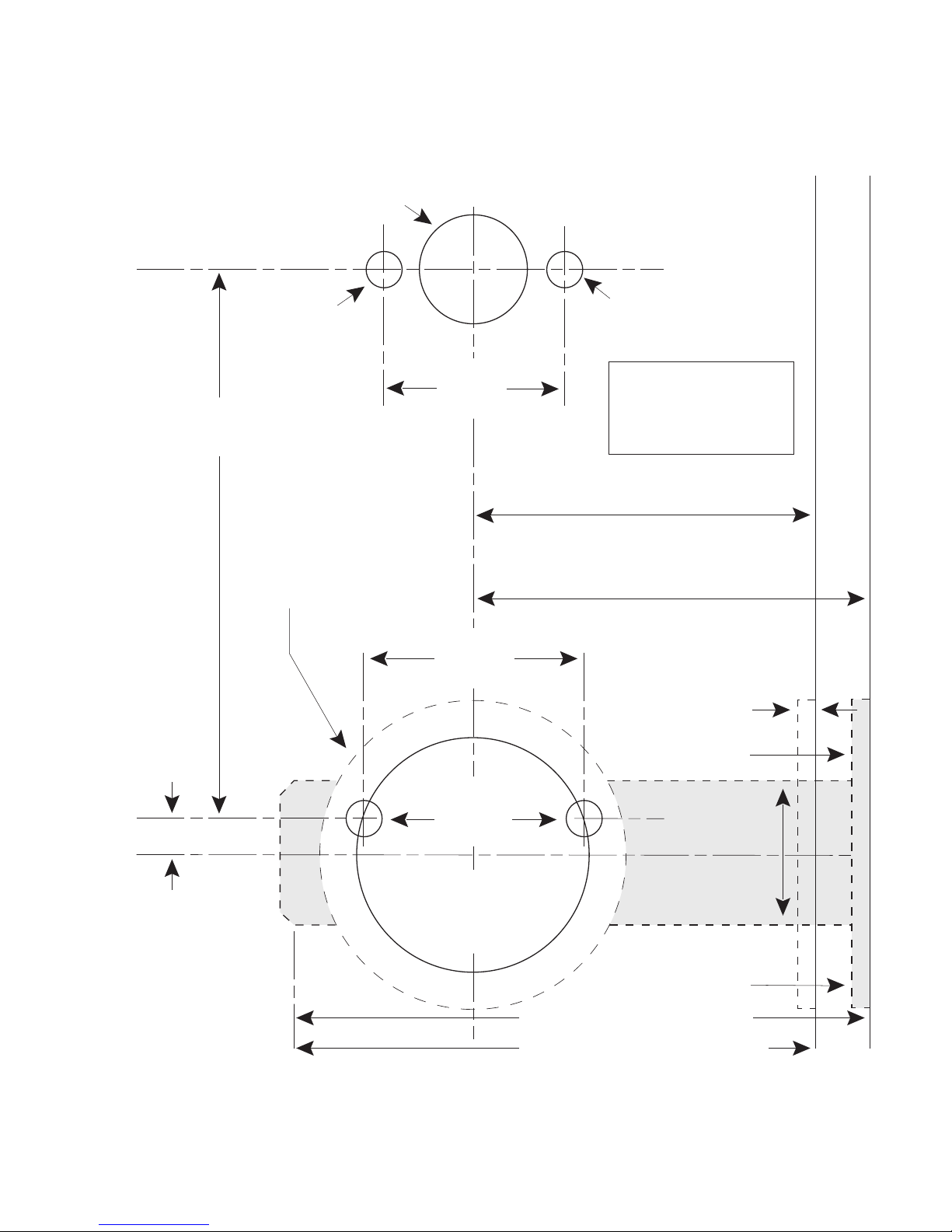
1
5
/8" dia.
(41 mm)
2
3
/4"
(70 mm)
1" dia.
(25 mm)
1
/8"
(4 mm)
1
/8"
(4 mm)
1
/4"
(6 mm)
Top
Bottom
1
1
/4"
(32 mm)
1
1
/2"
(38 mm)
3
/4"dia.
(19 mm)
1
/4" dia.*
(6 mm)
1
/4" dia.*
(6 mm)
1
/4" dia.*
(6 mm)
3
3
/4"
(95 mm)
Insert bolt, mark around
face plate of bolt,mortise
to depth required.
*BACKSET
*BACKSET
For door with existing 21/8"
(54 mm) dia. hole align template
with this circle.
*IMPORTANT
Drill the four
1
/4"
(6 mm) dia. holes
before all other holes.
2
3
/8"
(60 mm)
4" (100 mm) for 2
3
/4" *Backset
3
5
/8" (90 mm) for 2
3
/8" *Backset
Edge of door for 2
3
/8" (60 mm) Backset
(use 2
3
/4" (70 mm) backset for deadbolt cutout)
1
5
/8" dia.
(41 mm)
2
3
/4"
(70 mm)
1" dia.
(25 mm)
1
/4"
(6 mm)
Top
Bottom
1
1
1
/4"
(32 mm)
1
1
/2"
(38 mm)
3
/4"dia.
(19 mm)
1
/4" dia.*
(6 mm)
1
/4" dia.*
(6 mm)
1
/4" dia.*
(6 mm)
3
3
/4"
(95 mm)
Insert bolt, mark around
face plate of bolt,mortise
to depth required.
B
*BACKSET
*BACKSET
For door with existing 2 1/8"
(54 mm) dia. hole align template
with this circle.
*IMPORTANT
Drill the four
1
/4"
(6 mm) dia. holes
before all other holes.
2
3
/8"
(60 mm)
Edge of door for 2
3
/8" (60 mm) Backset
(use 2
3
/4" (70 mm) backset for deadbolt cutout)
4" (100 mm) for 2 3/4" *Backset
3
5
/8" (90 mm) for 2
3
/8" *Backset
1
/8"
(4 mm)
1
/8"
(4 mm)
I

KABA ACCESS CONTROL
2941 INDIANA AVENUE
WINSTON-SALEM, NC 27199-3770
NO POSTAGE
NECESSARY
IF MAILED
IN THE
UNITED STATES
BUSINESS REPLY MAIL
FIRST-CLASS MAIL
PERMIT NO. 1563
POSTAGE WILL BE PAID BY ADDRESSEE
WINSTON-SALEM, NC

Thank you for purchasing our product. In order to
protect your investment and to enable us to better
serve you in the future, please fill out this registration
card and return it to Kaba Access Control, or
register online at www.kabaaccess.com.
This lock will be used in what type of facility?
Commercial Building Industrial / Manufacturing Airport
College/University Government/Military School/Educational
Hospital/Healthcare Other (please specify)
What area is being secured with this lock? (e.g. Front Door, Common Door, Exercise Room)
This lock is:
New Installation
Replacing a conventional keyed lock
Replacing a Kaba Mechanical Pushbutton Lock
Replacing a Kaba Electronic Access Control
Replacing a Keyless Lock other than Kaba
How did you learn about Kaba Access Control Pushbutton Locks?
Advertisement Previous Use Internet / Web Another Use
Locksmith Maintenance Training Class Other (please specify)
What was your reason for buying this lock?
Who installed your lock?
Locksmith Maintenance Other
Check here if you would like more information on Kaba Access Control locks.
Name
Position
Company
Address
City
State ZIP (Postal Code) Country
Phone
Email
Name of Dealer Purchased From
Date of Purchase
Lock Model Number
REGISTRATION CARD

Notes

8
Verify the Combination Change Assembly
H-8 Insert the tip of a Phillips-head screwdriver
into the combination change assembly B
(See Figure 8-5).
H-9 Turn the central piece to the right (clockwise)
until it stops, DO NOT FORCE, (approximately
30˚ degrees) (See Figure 8-5).
H-10 Remove the screwdriver; the central piece
should automatically return to its initial
position.
H-11 If the central piece jams and does not return to its initial position, loosen
the two thru-bolts and push the combination change assembly B (See
Figure 8-5) upward or downward to properly center the tailpiece of the
combination change assembly, then tighten the two thru-bolts, and repeat
Steps H-8 to H-11.
I. INSTALLING THE STRIKE
I-1 Mark the vertical and horizontal center lines of the strike on the door frame
by using the center line of the bolt. Make sure the vertical and horizontal
center lines are well aligned with the bolt center lines.
I-2 Where the center lines meet, drill a 1" (25 mm)
diameter by 1
1
⁄8" (28 mm) deep hole to guaran-
tee that the bolt will be completely extended in
the door jam (See Figure 9-1).
I-3 Mortise (chisel out) the marked area to
1
⁄8" (3
mm) deep so that the strike will be flush with
the door frame.
I-4 Secure the strike with the four screws provided.
I-5 Close the door and turn the thumbturn to extend the bolt to ensure proper
alignment with the strike plate hole.
J. SETTING A NEW COMBINATION
IMPORTANT: The following steps must be performed while the DOOR IS OPEN.
The factory-set code is 2 and 4 pressed simultaneously, then 3. This code
should be changed as soon as the lock is installed.
J-1 Turn the outside thumbturn to the left (coun-
terclockwise) to the stop position (See Figure
10-1) and return it to the right (clockwise) slowly to the horizontal position. This will clear any
random buttons previously depressed.
8-5
B
9-1.
10-1

9
J-2 Enter the existing code (See Figure 10-2).
J-3 Insert a Phillips-head screwdriver into the cen-
ter of the combination change sleeve. Gently
turn to the right (clockwise) approximately
1
⁄8"
(3 mm) (See Figure 10-3). A slight click should
be felt. Do not force.
IMPORTANT: When removing the screwdriver,
the central piece must return to its initial position,
if not, set it back to its original position using the
screwdriver; see Section H-8 to H-11.
Verify the
Combination Change Assembly
.
J-4 Turn the outside thumbturn to the left (coun-
terclockwise) to the stop position, once only,
and slowly return it to the right (clockwise) to
the horizontal position (See Figure 10-4). to
clear the existing code from the mechanism.
J-5 Select a new code and write it down (some or
all of the buttons may be used for your new
code, pressed individually or simultaneously).
NOTE: A button may be used only once.
J-6 With the door open, enter your new code.
Depress each button fully and release. A slight
click should be felt (See Figure 10-5).
J-7 Turn the outside thumbturn to the right (clock-
wise) to the stop position (See Figure 10-6).
The bolt should retract. Now release the thumb
turn. Try to turn the thumbturn to the right
(clockwise). The thumbturn should not turn
clockwise unless the correct combination is
entered. If it turns and retracts the bolt without depressing any of the buttons, see J-9.
NOTE: Excessive force will result in slipping the
thumbturn 180˚ degrees. The slipping mechanism,
or force-proof clutch, protects the lock’s internal
mechanism from forced entry.
10-2
10-4
10-3
10-5
10-6

10
J-8 If a wrong combination is entered after the
desired combination has been programmed
into the lock, turn the outside thumbturn to
the left (counterclockwise) to the stop position
and release (See Figure 10-7). This will clear
any previously depressed buttons. Enter the
correct new combination (See Figure 10-8).
Turn the thumbturn to the right (clockwise) to
the stop position and release (See Figure 10-9).
The thumbturn should rotate. The bolt will be
retracted flush with the face plate. The correct
combination must be entered each time you
want to unlock the door.
J-9 If, without entering the combination, you can
retract the bolt by turning the outside thumbturn to the right, it means that a step was
done out of order and therefore no combination was entered. In this case, you must repeat
J-1 to J-7 but omit J-2, as the lock does not
have a combination.
K. INSTRUCTIONS FOR RESETTING
UNKNOWN COMBINATIONS
Remove and set aside the back plate held by on 4 screws. Remove the drive
cam assembly located on the control shaft on the back of the chamber.
Remove the combination chamber, held by 2 screws, from the lock.
To remove the 3-sided dust cover marked "Kaba Simplex," place the
combination chamber in the position below.
K-1 Place a small screwdriver on the edge of the
3-sided dust cover and push down on the
screwdriver (See Figure 11-1). The cover
should pop loose. Once it does, pull the
cover off of the combination chamber.
K-2 Hold the chamber in one hand by the screw
tab (b) on each end with the key-stems (c)
facing you and the control shaft (d) at the
bottom (See Figure 11-2).
K-3 Rotate the control shaft (d) counter-clockwise and release to clear the
chamber (See Figure 11-2).
K-4 Look at the 5 code gears (e). If any code gear pockets (f) are already
at the shear line (open position), ignore them. They are not used in
the combination (See Figure 11-3).
10-7
10-9
10-8
d
b
b
c (5)
(3 sided dust cover)
11-1
11-2

11
K-5 Find the code gear pocket/s (f) that is
farthest away from the shear line (open
position). Depress that key-stem/s (c) and
release (See Figure 11-3).
K-6 Find the code gear pocket/s (f) that is the next
farthest away from the shear line (open position). Depress that key-stem/s
(c) and release (See Figure 11-3).
K-7 Repeat step K-6 until all code gear pockets (f) are at the shear line
(open position).
K-8 If all the code gear pockets (f) are not lined up at the shear line
(open position), start over at step K-3.
K-9 Depress the lockout slide (g) at the top of the chamber and release. (looks
like one end of a spark plug) (See Figure 11-4).
K-10 Rotate the control shaft (d) counter-
clockwise to clear the chamber and release.
The lockout slide (g) should pop out (button
will not move yet) (See Figure 11-4).
K-11 Depress the key-stem/s (c) that you want in
your new combination, releasing each after it is
depressed (See Figure 11-2).
K-12 Once you have depressed all the digits in your new combination, turn the
control shaft (d) clockwise (See Figure 11-4). The code change button (h)
under lockout slide (g), should pop up (See Figure 11-4). Your new combination is now set.
K-13 Look at the code gear pockets (f). The numbers in you new combination
should not be at the shear line (open position) (See Figure 11-3).
Reinstallation: Replace the 3-sided dust cover marked “Kaba Simplex.” Make
sure the staked joints on both end plates fit through the slots on the dust
cover. Stake the end 2 plate joints. Replace the combination chamber into the
lock using the same 2 screws removed earlier. Slip the drive cam assembly
back on the control shaft of the chamber assuring it is in the same position
as prior to removal. Re-secure the back plate, assuring the tailpieces are seated correctly using the same 2 screws removed earlier.
Testing: Enter the combination you preset during the reset process. Turn the
outside thumbturn to the right (clockwise). The latch should retract. If the
latch does not retract, turn the outside thumbturn left (counter-clockwise)
and release, then enter the code again.
f
g
c (5)
e
(5)
h
g
f
d
11-3
11-4
d

12
L. TROUBLESHOOTING
?
Lock fails to open when combination is entered and outside thumbturn is
rotated clockwise.
Buttons were not fully depressed when the combination was entered.
Lock not cleared of previous attempts to enter access codes.
Turn the outside thumbturn to the left to clear the wrong entry. Enter the
combination making sure you feel each button click to know that
it was depressed fully. Turn thumbturn clockwise.
?
Turning outside thumbturn clockwise always retracts latch without
depressing any buttons.
Lock is in zero combination.
Follow the procedure for setting a new combination (Section J, but omit
Step J-2).
?
Inside thumbturn only retracts bolt partially or not at all, in either clock-
wise or counterclockwise direction.
Bolt was not properly installed.
Remove and re-install the bolt. Review and follow instructions in Section E.
?
After setting a new combination, the lock works one time only, then fails to
open.
Buttons of intended combination were not fully depressed when changing
combination.
This is a lost combination situation. Review and follow instructions in
Section K.
For technical assistance please call
1-800-849-TECH (8324) or 336-725-1331

13
Notes

Kaba Access Control
2941 Indiana Avenue Winston-Salem, NC 27105 USA
Tel: (800) 849-8324 (336) 725-1331
Fax: (800) 346-9640 (336) 725-3269
www.kabaaccess.com
PK 2387 0307
 Loading...