

Kuppersbusch KD 9660.0GE, KDUM 9660.0GE, KD 12660.0GE, KDUM 12660.0GE Instructions For Use And Installation Instructions

227954 R31
BEDIENUNGSANWEISUNG
mit Montageanweisungen
Instructions for use and installation instructions
Instructions d'utilisation et avis de montage
Gebruiksaanwijzing en montagehandleiding
Istruzioni di uso e di montaggio
Instrucciones de uso y de montaje
Instruções de uso e de montagem
KD 9660.0GE
KDUM 9660.0GE
KD 12660.0GE
KDUM 12660.0GE
18
GB
Disposing of the packaging
Please ensure the environmentally-friendly disposal of the packaging that came with your appliance. Recycling the packaging
material saves on resources and cuts down on waste.
Disposing of old appliances
The symbol on the product or on its packaging
indicates that this product may not be treated as
household waste. Instead it must be handed
over to a collection point for the recycling of
electrical and electronic equipment.
By ensuring that this product is disposed of cor-
rectly you will help to protect the environment
and human health, which could otherwise be harmed through the
inappropriate disposal of this product. For more detailed information about recycling this product, please contact your local city
office, your household waste disposal service or the shop where
you purchased the product.
Appropriate use
The hood is intended for extracting steam above electric and gas
cookers in households. It may not be used for any other purpose
and may only be used under supervision.
For your information...
Please read this manual carefully before using your hood. It contains important information on safety and on how to use and look
after your appliance so that it will provide you with many years of
reliable service.
Should your appliance develop a fault, please first consult the
section on “What to do if trouble occurs?”. You can often rectify
minor problems yourself, without having to call in a service engineer.
Please keep this manual in a safe place and pass it on to new
owners for their information and safety.
Contents
Safety instructions................................................................. 19
Connection and operation..................................................... 19
The hood in general.............................................................. 19
Concerning persons.............................................................. 19
Appliance description............................................................ 20
Operation................................................................................ 21
Instructions for using the hood.............................................. 21
Switching on the fan and selecting a fan setting................... 21
LED lamp.............................................................................. 21
Timer (automatic switch-off).................................................. 21
Maintenance and care............................................................ 22
Why maintenance? ............................................................... 22
Maintenance cycles .............................................................. 22
Cleaning the hood................................................................. 22
Opening the hood ................................................................. 23
Cleaning the inside of the hood ............................................ 23
Cleaning the metal grease filters .......................................... 24
Replacing the charcoal filters (recirculation air
operation only)...................................................................... 24
Cancelling the saturation display (LEDs 1 and 4) ................. 24
Cancelling the saturation display (LEDs 2 and 3) ................. 24
Replacing the LED lamp....................................................... 25
What to do if trouble occurs ................................................. 26
Assembly instructions........................................................... 27
Note ...................................................................................... 27
General information on outgoing air or recirculating air........ 27
Ordering a conversion kit...................................................... 27
Safety instructions for the extraction air mode...................... 27
Tips on the outgoing air duct................................................. 28
Exhaust air pipe.................................................................... 28
Electric connection................................................................ 28
Important information ............................................................ 28
Installation ........................................................................... 29
Start of operation .................................................................. 31
Technical data ..................................................................... 31
Safety instructions
GB
19
Safety instructions
Connection and operation
• The appliances are constructed in accordance with the relevant safety regulations.
• Repairing the appliances is a job that should be left to a qualified electrician according to valid safety regulations. For your
own safety, do not allow anyone other than a qualified service
technician to install, service or repair the product.
The hood in general
• In order to avoid damage and risks as a result of improper
operation, it is essential that these instructions for use be followed and be stored in a safe place.
• Should the appliance change hands, the instruction manual
should be passed on too.
• Cooking zones should always be covered with pots or pans to
prevent the strong heat from damaging the hood.
• Open flames are not permitted, since they damage the filters
and may start a fire. This does not include the proper use of a
gas cooker, i.e. the cooking zones must always be covered
with pots or pans.
• Constant supervision is essential when deep-frying or cooking
with oil or fat under the hood. There is a risk of fire if the frying
fat overheats or ignites itself. Avoid using fat which is not clean
or is old, since it is more likely to catch alight.
• Never flambé under the hood because of the risk of fire caused
by rising flames which could ignite the fat collected in the filter.
• It is essential to ensure a sufficient supply of fresh air in the
kitchen when the hood is in operation in the extraction air
mode and heating systems requiring a chimney are in operation.
• The hood may not be used without metal grease filters since it
will then be soiled on the inside.
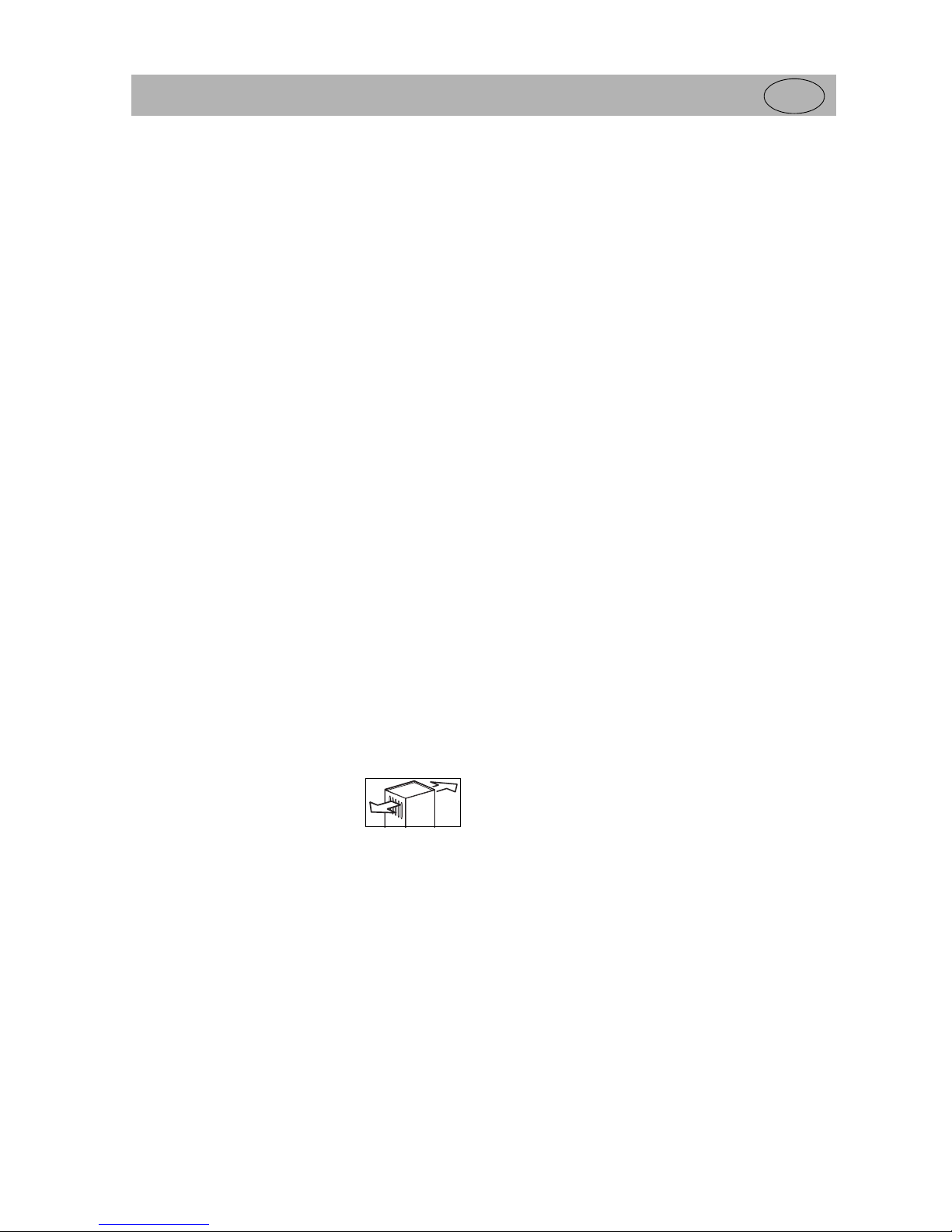
• The air outlets may not be covered
during recirculation air operation in order
to enable the air to escape freely.
• The hood may not be cleaned with a
steam cleaner since safety can no longer be guaranteed due
to the steam.
• Do not look into the intensive source of light for too long!
• It is absolutely essential to observe maintenance and cleaning
cycles as failure to do so results in a risk of fire as fat deposits
may ignite.
• Disconnect the hood from the mains supply whenever it is
serviced or cleaned.
• When mounting the hood, the minimum clearance to cooking
zones must be 65 cm for electric cookers and 75 cm for gas
cookers. Smaller clearances are not permissible due to the risk
of fire.
• National building regulations stipulate certain restrictions when
cooker hoods and household furnaces connected to chimneys,
such as coal stoves, oil stoves and gas hot water boilers, are
operated in the same room.
The German regulation on firing heating systems only permits
a maximum negative pressure of 0.04 bars in such rooms.
Negative pressure occurs in a closed room as soon as an
extraction air system (cooker hood) is switched on.
Suitable measures must be taken in order to ensure that there
is a sufficient supply of fresh air for operation of the cooker
hood in the extraction air mode.
• Keep packaging material such as plastic bags away from children.
Concerning persons
• This appliance is not intended to be used by persons (including children) with physical, mental or sensory impairments or
by persons (including children) who lack the required experience or know-how, unless such persons are supervised by a
person responsible for their safety or have been given instructions on how to use the appliance by a person responsible for
their safety.
Children should be supervised in order to ensure that they do
not play with the appliance.
20
Appliance description
GB
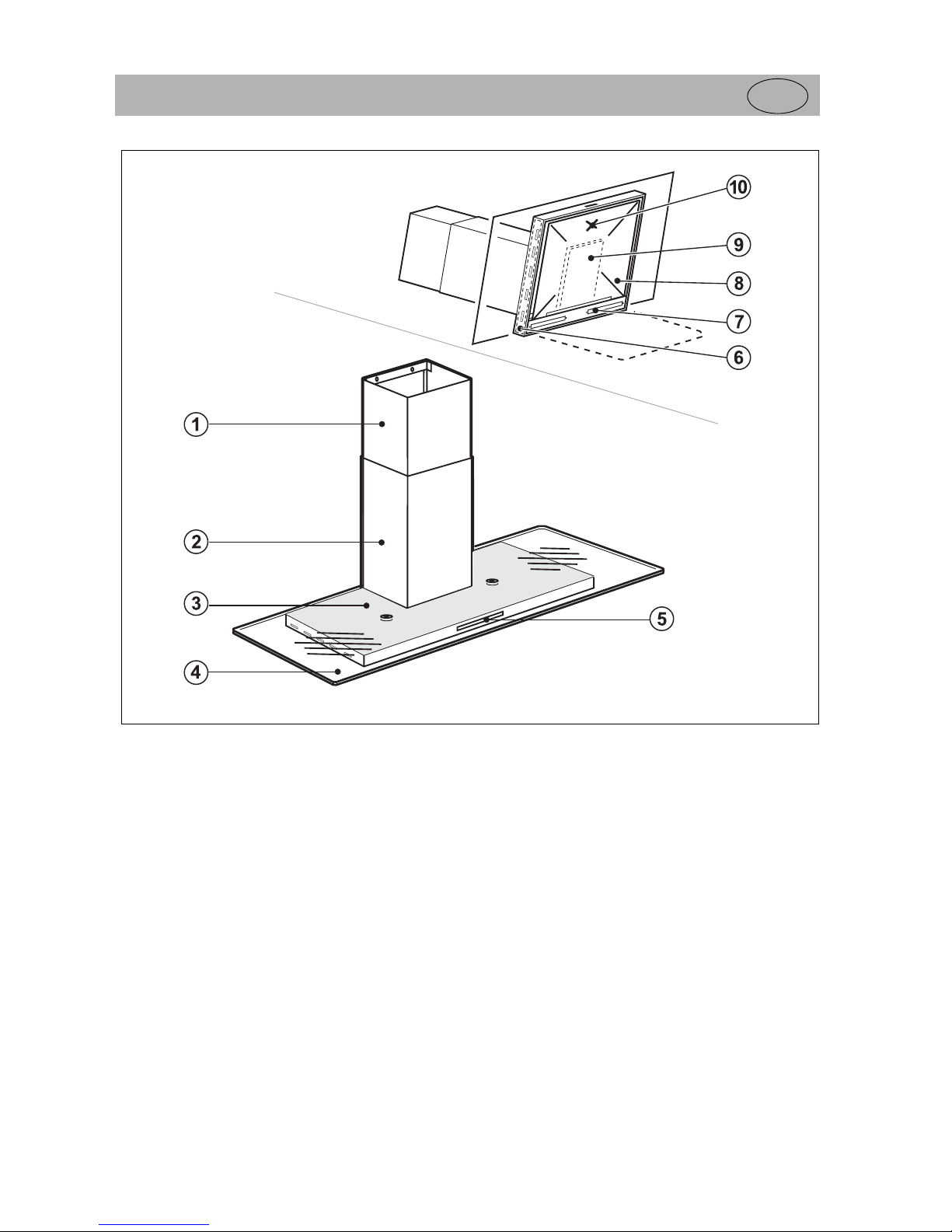
Appliance description
1. Chimney top
2. Chimney bottom
3. Canopy
4. Glass canopy (safety glass)
5. Control elements
6. Metal grease filters, both sides, 2 filters
7. LED lamp
8. Metal screen
9. Metal grease filter
10. Pressure point for opening (see p. 23)
Operation
GB
21
Operation
Instructions for using the hood
The power setting of the hood should be adapted to the occurrence of steam during cooking and frying, i.e. for little steam a
low setting should be chosen; the setting should be higher when
a lot of steam occurs.
Please ensure that the hood is switched on at the same time as
the hob so that an air current can build up. This has a positive
effect on the extraction rate. The hood should still run for a while
on completion of cooking so that remaining odours and residual
moisture can be extracted.
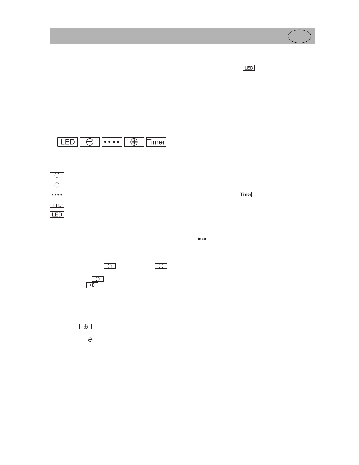
........... Minus button
(reduce the fan speed)
........... Plus button
(increase the fan speed)
........... Display
........... Timer button
........... Lamp button
Switching on the fan and selecting a
fan setting
The hood is equipped with a fan with several speed settings.
Pressing the
Minus button
or the
Plus button
will
switch the fan on.
Using the
Minus key
will immediately select fan setting 4;
using the Plus key will select the first fan setting.
The fan setting is shown by the lighting up of 4 LEDs in the dis-
play.
Switching off the fan
If the
Plus key
is pressed when the fan setting is at 4, the
hood will be switched off.
If the
Minus key
is pressed when the fan setting is at 1,
the hood will also be switched off.
LED lamp
Pressing the
Lamp button
will switch the lamp on and off.
Timer (automatic switch-off)
The hood is equipped with an automatic switch-off device which
can be used to programme switching off the hood after cooking.
Procedure
• Switch the hood on and select a fan setting from 1 – 4. The
delayed stop time depends on the fan setting selected:
Fan setting 1 - 20 min.
Fan setting 2 - 15 min.
Fan setting 3 - 10 min.
Fan setting 4 - 5 min.
•
Press the Timer key
once. The information blinks in
the display. The automatic switch-off device has been activated.
Please note:
• To deselect the programming mode, press the
Timer key
once in acknowledgement or switch the hood off manu-
ally. The display will no longer blink.

22
Maintenance and care
GB
Maintenance and care
The mains plug must be pulled out or the fuse
switched off or screwed out before maintenance or
cleaning work is carried out on the hood!
Why maintenance?
Carry out regular maintenance on your hood! Maintenance is
essential in order to ensure that the hood works properly and
effectively and that the risk of the grease filters catching alight
does not arise.
The metal grease filters should be regularly cleaned in good time
in order to ensure that they work properly and that the
performance of the hood is not impaired.
Maintenance cycles
Metal grease filter
The metal grease filter should be cleaned once a month in the
case of normal household use or alternatively whenever the
display lights up after approx. 40 hours of operation.
To cancel see the section “Saturation display”.
Charcoal filter (recirculation air operation only)
In the case of normal household use the charcoal filter can
absorb odorants for up to six months before it needs to be
replaced or alternatively, it must be replaced whenever the
display lights up after approx. 230 hours of operation.
To cancel see the section “Saturation display”.
The charcoal filter must be replaced sooner when the hood is
used more frequently and odours are not sufficiently reduced.
The metal filter should be cleaned in good time and the charcoal
filter replaced, in particular in the case of recirculation air
operation, in order to avoid undesirable deposits of greasy
vapours and condensate on kitchen units. Besides, a clogged
metal filter will no longer be able to absorb particles of fat and
these will then be unnecessarily deposited on the charcoal filter,
thus impairing the effect of the odour filter.
Cleaning the hood
The hood may only be cleaned when the mains plug
has been pulled out or the fuse switched off!
Use only a mild cleaning agent (e.g. detergent) to wipe
the outer surfaces of the hood and then dry it with a clean cloth.
No aggressive cleaning agents, scouring agents or sharp items
should be used. Stainless steel surfaces can be cleaned with a
commercially-available stainless steel cleaning agent and a soft,
non-abrasive sponge or cloth. When cleaning stainless steel
surfaces, wiping motions should always correspond with the
direction of the structure in order to avoid scratches.
Clean the glass surfaces with household glass cleaners only and
then rub the glass dry.
blink alternately
blink alternately

Maintenance and care
GB
23
Opening the hood
Disconnect the hood from the mains or switch off
the fuse!
Opening the metal screen
•
Press
in the middle of the metal screen, around 30 mm from
the front edge. The lock is released (soft
CLICK
).
Magnets will keep the metal screen in a horizontal position.
• To open put your hand into the edge suction from the side and
gently pull the metal screen so that it swings open.
Closing the metal screen
• Swing the metal screen upwards until the magnets hold it in a
horizontal position.
• Then press onto the same point used for removing the metal
screen so that the lock engages again (soft
CLICK
).
To ensure that the metal screen has engaged properly, put
your hand into the edge suction from the side and pull gently;
the metal screen must remain at the top.
Removing the metal screen
The metal screen can be removed to clean it. It must hang
downwards to remove it; the hood is open.
Caution – it could fall onto the hob, so please hold it firmly!
Protect the hob located below the hood with a thick blanket!
• To remove the metal screen, hold it and press the bolt on the
bearing inwards; this will release the metal screen on one side.
It can then easily be removed on the other side.
• Proceed in reverse order to replace the metal screen.
Cleaning the inside of the hood
Pull out the power plug or disconnect the fuse!
The metal screen must be removed for cleaning pur-
poses!
Deposits on easily accessible areas on the inside of the hood can
be wiped away carefully with a damp cloth and some detergent.
Please always work carefully as there is a risk of sharp
edges causing injury.
Clean the outer surface of the motor as well.
Ensure that no moisture gets into electrical parts.
Metal screen
press bolt

24
Maintenance and care
GB
Cleaning the metal grease filters
Disconnect the hood from the mains or switch off
the fuse!
Make sure that the grid is not damaged when you
clean the metal grease filter. Frequent cleaning may cause
the colour of the metal to change; this will not affect the
functioning of the filter.
Removing / installing metal grease filter (a)
The metal grease filter is located behind the metal screen and
can only be accessed when the hood is open.
• To remove the metal grease filter, disengage it on the bar rail
handle and remove it from its installation frame.
• Proceed in reverse order to replace the filter.
Removing / installing metal grease filters (b)
The two metal grease filters (b) are located on the left and right
inside the canopy.
• To remove the metal grease filter, first of all hold the back pin
and guide it along the side past the hinge. Then remove the
metal grease filter.
• To install the filter, proceed in reverse order, i.e. first of all
insert it in the frame at the front and then guide it along the
side next to the hinge. Finally press the metal grease filter
securely into the frame.
Cleaning by hand
• Soak the metal filter well in hot water with a detergent and then
rinse it off with hot water. Repeat the procedure if necessary,
depending on how greasy it is.
Rinsing in a dishwasher
• Lay the metal grease filter down flat in the dishwasher so that it
can be optimally cleaned. An intensive programme, at 65°C if
possible, should be selected in order to fully remove deposits
of fat.
Restore the mains power supply.
Replacing the charcoal filters
(recirculation air operation only)
The charcoal filter is located directly
behind the metal grease filter. The
metal grease filter will need to be
removed in order to replace the
charcoal filter.
• Put the charcoal filter onto the
inside of the metal grease filter.
• Clamp the fastening clamp on the
one side (1).
Then bend the two middle rods
slightly by hand (2) and clamp
them on the other side (3).
Also clamp the two individual rods
(4).
Proceed in reverse order to remove.
Cancelling the saturation display
(LEDs 1 and 4)
(metal grease filter)
After approx. 40 hours of operation LEDs 1 and 4 will blink
alternately for a few seconds when the hood is switched on.
The metal grease filter needs to be cleaned.
Pressing the
Minus button
and the
Plus button
simultaneously will clear the counter of the saturation display.
Cancelling the saturation display
(LEDs 2 and 3)
Charcoal filter (only present for recirculation air
operation)
After approx. 230 hours of operation LEDs 2 and 3 will blink
alternately for a few seconds when the hood is switched on.
The charcoal filter (recirculation air operation only) needs to be
replaced.
This saturation display is not significant for the
extraction mode.
Pressing the
Minus button
and the
Plus button
simultaneously will clear the counter of the saturation display.
Metal grease filters (b)
Metal grease filter (a)
Pin
Hinge
blink alternately
blink alternately

Maintenance and care
GB
25
Replacing the LED lamp
Disconnect the hood from the mains or switch off
the fuse before replacing the lamp.
Do not look into the intensive light source (LED) for
any length of time!
Only an original LED strip may be installed; these are only
available from Customer Service.
Recommendations
• Protect the hob located below the hood with a thick blanket!
• Please touch an earthed metal object (e.g. a heating element)
in order to prevent electrostatic charging.
Procedure
• Open the metal screen and remove it (see previous section)
• Remove the screws with a screw driver. Remove the coloured
plugs. This can be done carefully with your finger nail or a
kitchen knife.
• The light covering (plastic) and the metal screen will come lose
right across.
Caution – it could fall onto the hob, so please hold it
firmly!
• Remove the metal grease filter (possibly with the charcoal
filter). The plug contacts for the LED strip will be accessible.
Remove the plug contact.
• Remove the coloured plugs. This can be done carefully with
your finger nail or a kitchen knife.
The LED strip can be removed.
• Install the new LED strip in reverse order.
• Restore the mains power supply.
Metal screen
LED strip
Plugs
Screws
Metal grease filter
Plug contact
plugs
LED strip

26
What to do if trouble occurs
GB
What to do if trouble occurs
Interference with and repairs to the hood by
unqualified persons are dangerous as they can
result in electric shock, or short circuit. Do not
interfere with or try to repair the appliance; this
could cause injury to persons and damage to the appliance.
Therefore always have such work done by a qualified electrician, e.g. Customer Service.
Below are some tips for rectifying faults yourself.
The hood does not function at all.
• Is the plug in the socket?
• Has the fuse for the domestic wiring system tripped?
Has the hood developed a malfunction.
• Switch the hood off with the buttons and disconnect it from the
mains for a few seconds by removing the plug or switching off
the fuse.
The suction power is not strong enough.
• Has the right fan speed been set?
• Has the metal grease filter been cleaned?
• Was the charcoal filter replaced in good time?
• Is the air removed from the kitched replaced with a sufficient
supply of fresh air so that no negative pressure develops?
• Are the air outlets blocked?
• During installation, was the outlet air duct miscalculated or not
properly installed? (e.g. diameter too small, exhaust air pipe
too long or exhaust air duct too angled)?
The hood is suddenly much noisier during
operation.
• Does sufficient fresh air flow into the kitchen when the extraction air mode is operated?
Have operation noises become louder with time.
• Have the maintenance cycles of the filters been observed to
allow air to get in at all?
The LED lamp does not work.
• Has the fuse for the domestic wiring system tripped?
• Was the new LED lighting properly connected to the power
supply (plug connection)?
When the hood is switched on, two LEDs will
blink alternately for a few seconds (saturation
display).
Please clean the metal grease filter or replace the charcoal filter.
Pressing the
Minus button
and the
Plus button
simultaneously will clear the counter of the saturation display.

Assembly instructions
GB
27
Assembly instructions
Note
KÜPPERSBUSCH cooker hoods may only be built-in in
accordance with the instructions included in this manual. In
the case of failure to observe these instructions,
KÜPPERSBUSCH shall decline any liability and the
approved marks of conformity will become invalid!
General information on outgoing air
or recirculating air
The chimney hood may be operated in the recirculating air mode
or the extraction mode, depending on the model.
In the
recirculating air mode
air above the hob is extracted,
cleaned and returned to the kitchen. The polluted air is cleaned
by the metal grease filter, which absorbs residual fat, and the
charcoal filter, which filters out odorants.
In the
extraction mode,
residual fat is cleaned from the air which
has been extracted and lead outside through the exhaust air
pipe. The recirculating air mode should in principle only be used
when no air duct or outer wall is available.
Ordering a conversion kit
Please contact the Küppersbusch Customer Service to order a
conversion kit for the respective other operation mode.
You will find the address on page 2.
Safety instructions for the
extraction air mode
Operating the hood in the extraction air mode in
kitchens with household furnaces requiring a
chimney:
National building regulations stipulate certain restrictions when
cooker hoods and household furnaces connected to chimneys,
such as coal stoves, oil stoves and gas hot water boilers, are
operated in the same room.
The German regulation on firing heating systems only permits a
maximum negative pressure of 0.04 bars in such rooms. Negative pressure occurs in a closed room as soon as an extraction
air system (cooker hood) is switched on. Pressure may only be
equalised with an inflow of fresh air from outside and not by
means of the household furnace. It must be ensured that no carbon monoxide is extracted from the heating source.
Suitable measures must be taken in order to ensure that there is
a sufficient supply of fresh air for operation of the cooker hood in
the extraction air mode. A wall box ensures that fresh air flows
into the room.
When making an assessment, the entire ventilation system of the
home must be taken into consideration, since an insufficient
inflow of fresh air may cause exhaust gases from the household
furnace to flow into the home.
Your regional master chimney sweeper will give you relevant
information.
Operating the hood in the extraction air mode in
kitchens with no household furnace requiring a
chimney:
In rooms with no household furnace the rule is that the air inlets
must be at least as big as the air outlets in order to avoid impairing the functioning of the cooker hood. You can, for example,
leave the kitchen window ajar when the hood is in operation.
Connecting the hood to a chimney or a duct:
The hood may not be connected to:
- a smoke or exhaust gas flue which is in operation
- a shaft used for ventilating rooms with a household furnace.
Approval must also be granted by the regional master chimney
sweeper when the hood is to be connected to smoke or exhaust
gas flues which are not in operation!
Safety instructions on minimum clearances
For reasons of safety, the minimum
clearance between hobs and hoods
is
• 65 cm for electric cookers
• 75 cm for gas cookers
These clearances should not be significantly exceeded since the hood
output has been adapted accordingly.
Clearance

28
Assembly instructions
GB
Tips on the outgoing air duct
Only suitable materials which are as flame resistant as possible
may be used for connecting the hood with an extraction air system (e.g round pipe, square system, flexible aluminium hose,
etc.). The extraction rate of the hood also depends to a large
extent on the type, guide and length of the extraction air system.
The extraction rate will be optimal when resistance to the air flow
is maintained at a low level with the following properties:
• Smooth inner surfaces of the pipes
• Pipe diameters as large as possible
• Large pipe bends instead of narrow pointed bends
• Exhaust air pipes as short as possible (max. 5 m)
• As straight as possible instead of many changes in direction
• Avoiding reductions in cross-sections (e.g. connecting pieces)
or changes in the shape of cross sections (e.g. round - flat)
Serious deviations from the properties indicated may result in
drastic reductions in output.
Exhaust air pipe
The extraction air connection piece has an external diameter of
150 mm and the reducer (if included in the scope of delivery) is
125 mm in diameter.
No wider or narrower pipe diameters may be used as they are
unsuitable.
When laying the exhaust air pipe, it is essential to make sure that
all the connection points and transitions between pipe sections
are fitted tightly and are waterproof. This will prevent the used
exhaust air from escaping unintentionally.
Electric connection
The hood is fitted with a mains cable and a plug and can be connected to any shockproof socket supplying 230 volts of alternating current, 50 Hz which has been installed in accordance with
regulations.
If the mains cable of this appliance is damaged it will need to be
replaced with a special connection cable. In order to avoid any
risks, this must be carried out by the manufacturer or his Customer Service.
The shockproof socket must be accessible.
If, after installation of the hood, the shockproof socket or the
mains plug are no longer accessible behind the chimney cover,
an additional two-pole isolator must be installed to enable the
hood to be cut off from the power supply.
A qualified electrician must install an isolator in accordance with
EN 60664-1 overvoltage category III.
Important:
Permanent installations are always to be carried out by an
authorised electrician in accordance with currently valid regulations!
Important information
• Before installating the hood, please check to ensure that the
material for mounting (screws, dowels, etc.) is suitable for your
wall or ceiling.
• When drilling holes for dowels make sure that lines running in
the walls (electricity, gas and water) are not damaged.
• Switch off the safety fuse in the fuse box for the main socket so
that no injuries can result during installation.

Assembly instructions
GB
29
Installation
Mount the body of the hood at the required height in the centre
above the hob. Use the holder, screws and dowels supplied.
Insert a locking screw into the dowel. The hole for the locking
screw can be accessed from the inside of the hood. To access
the hole, open the metal screen and remove the grease filter. It is
located in the middle above the cross section on the back.
Use the M5x20 screws supplied to adjust the body of the hood
into a horizontal position.
Install the mounting bracket (1) for the top part of the chimney
underneath the ceiling with screws and dowels.
Install the mounting bracket (2) for the bottom part of the chimney
with screws and dowels.
Make the connection for extraction air (see the previous section).
Switch the safety fuse in the fuse box off and put in the mains
plug (if present) or make an electrical connection.
2
1
Dowel 6 mm
Dowel 6 mm
Dowel 8 mm
Dowel 8 mm
Locking screw
2
1

30
Assembly instructions
GB
Mount the air deflecting box and the mounting bracket (1) for the
top part of the shaft. Insert a pipe connection between the hood
and the air deflecting box (not included in delivery).
Install the two parts of the chimney that have been put together
onto the body of the hood.
Here the longer bottom chimney part is hung up onto the mounting bracket (2). Pressing it down a little will engage it properly into
the groove of the hood body.
Pull the top part of the chimney upwards until it reaches the ceiling.
Fasten the top chimney part with screws.
1
Recirculating air mode only
2

Assembly instructions
GB
31
Do not replace the glass canopy until the hood and the chimney
have been completely installed.
Fasten the glass canopy with screws. Do not use a battery-operated screw driver!
Start of operation
After installing the hood, check the functions (lighting and fan).
Technical data
KD 9660.0GE
KDUM 9660.0GE
Dimensions
Height/ Width/ Depth . . . . . . . mm 650 - 1000 x 900 x 520
Extraction air connection piece
Outer diameter. . . . . . . . . . . . mm 150
Weight
approx. . . . . . . . . . . . . . . . . . . kg 32
Electrical connection
2 lamps . . . . . . . . . . . . . . . . . . W
Motor . . . . . . . . . . . . . . . . . . . . W
230 V, 50Hz
4.5
75 - 195
Fan nominal output
. . . . . . m3/h 755
Hood maximum
extraction rate
. . . . . . . . . . m3/h 257 - 629
Max. noise
. . . . . . . . . . . . db (A) 48
KD 12660.0GE
KDUM 12660.0GE
Dimensions
Height/ Width/ Depth . . . . . . . mm 650 - 1000 x 1200 x 520
Extraction air connection piece
Outer diameter. . . . . . . . . . . . mm 150
Weight
approx. . . . . . . . . . . . . . . . . . . kg 39
Electrical connection
2 lamps . . . . . . . . . . . . . . . . . . W
Motor . . . . . . . . . . . . . . . . . . . . W
230 V, 50Hz
5.4
75 - 195
Fan nominal output
. . . . . . m3/h 755
Hood maximum
extraction rate
. . . . . . . . . . m3/h 257 - 629
Max. noise
. . . . . . . . . . . . db (A) 48

© Teka Küchentechnik GmbH
März 2010
 Loading...