

Küppersbusch KD 934.1, KD 634.1, KD 935.1, D 933.0, D 633.0 Instructions For Use And Installation Instructions
BEDIENUNGSANWEISUNG
mit Montageanweisungen
Instructions for use and installation instructions
Instructions d’ utilisation et avis de montage
Gebruiksaanwijzing en montagehandleiding
Istruzioni di uso e di montaggio
Instrucciones de uso y de montaje
Instruções de uso e de montagem
KD 934.1 / 634.1
538431 G61
For your information...
You should carefully read the information in this manual before you use
your cooker hood. Here you will find important notes concerning safety and
how to use, look after and service your appliance so that it enjoys a long
service life.
Should a fault arise, please first consult chapter “What to do if trouble
occurs”. You can often remedy minor faults yourself and thus save unnecessary service costs.
Always keep these instructions in a safe place and pass them on to new
owners for their information and safety.
Conditions of guarantee
The conditions of guarantee applicable for this product are subject to those
published by the representative in the relevant country.
Details regarding same may be obtained from the dealer from whom the
appliance was purchased. For claims under guarantee the sales receipt
must be produced.
Contents
Safety instructions . . . . . . . . . . . . . . . 12
For connections and functions
For operating your cooker hood
For operating the hood with stoves and heating appliances with a naked flame
General advice . . . . . . . . . . . . . . . . . . 12
Your appliance at a glance. . . . . . . . . . 13
Using the hood. . . . . . . . . . . . . . . . . . 13
Before using your appliance for the first time
Switching the lighting On / Off
Switching on the ventilation
Changing the ventilation setting
Switching the ventilation off
Cleaning, care and maintenance . . . . . . 14
Cleaning the metal fat filters
Changing the activated charcoal filters (for recirculation mode)
Replacing a halogen lamp
What to do if trouble occurs. . . . . . . . . 15
Rating label
Installation . . . . . . . . . . . . . . . . . . . . 15
Scope of delivery
Dimensions for installation
Installation preconditions
Mounting a steel rear panel (optional)
Attaching wall hooks and chimney support
Fitting the hood
Ducting and chimney attachment
Fitting the grease filters
Guideline for extraction paths. . . . . . . . 18
KD 934.1 / KD634.1 11
Safety instructions
For connections and functions
Maintenance and repair work may only be carried out by an authorised
technician in accordance with the applicable safety regulations. Work
which has been performed improperly can endanger your safety.
Extraction appliances must not be connected to smoke or fume chimneys or to shafts used for ventilating rooms where stoves have been installed. Before extracting fumes into a smoke or fume chimney which is
not in use, please obtain approval from your local chimney sweep.
When extracting fumes, please observe the official regulations.
The minimum distance between the cooker hood and the cooker is
650 mm.
It must also be possible to access the mains plug after the appliance
has been installed. Otherwise, the household fuse must be switched off
before cleaning and maintenance work is carried out.
For operating your cooker hood
The fat filter must be cleaned and replaced regularly. There is a danger
of fire if the appliance is used with a saturated fat filter!
Only use the hood when the fat filters have been installed.
Never flambé dishes under the cooker hood!
Ignited rings of gas cookers and gas hobs must always be covered by
pots or pans.
Keep an eye on deep-fat fryers while in operation. Fat and oil which igni-
tes due to overheating can set fire to the cooker hood.
Always keep children away from the cooker hood.
For operating the hood with stoves and heating
appliances with a naked flame
This relates, for example, to gas, oil or coal-fired heating appliances, continuous flow heaters and hot water tanks: If the cooker hood is operated in
extraction mode, such appliances may no longer have sufficient air required
for combustion and there is a danger of intoxication or explosion!
Operation is perfectly safe if the cooker hood and the stove are being used
simultaneously in rooms where a negative pressure of 0.04 mbar is not
exceeded. This ensures that the fumes from the stove are not sucked back
into the room.
This can be achieved if there are non-airtight openings in windows and
doors, ventilation wall boxes (supplying/extracting air) or other technical
devices, e. g. interlock devices so that a sufficient supply of combustion
air can flow back into the room.
When assessing the ventilation requirements, the ventilation system of
your entire home must always be taken into account. This means, for example, the above regulations for operating cooking appliances (e.g. hobs
and gas cookers) are not applied. If in doubt, please consult your local
chimney sweep.
If the cooker hood is only used in recirculation mode - with activated
charcoal filters - there are no restrictions on operation
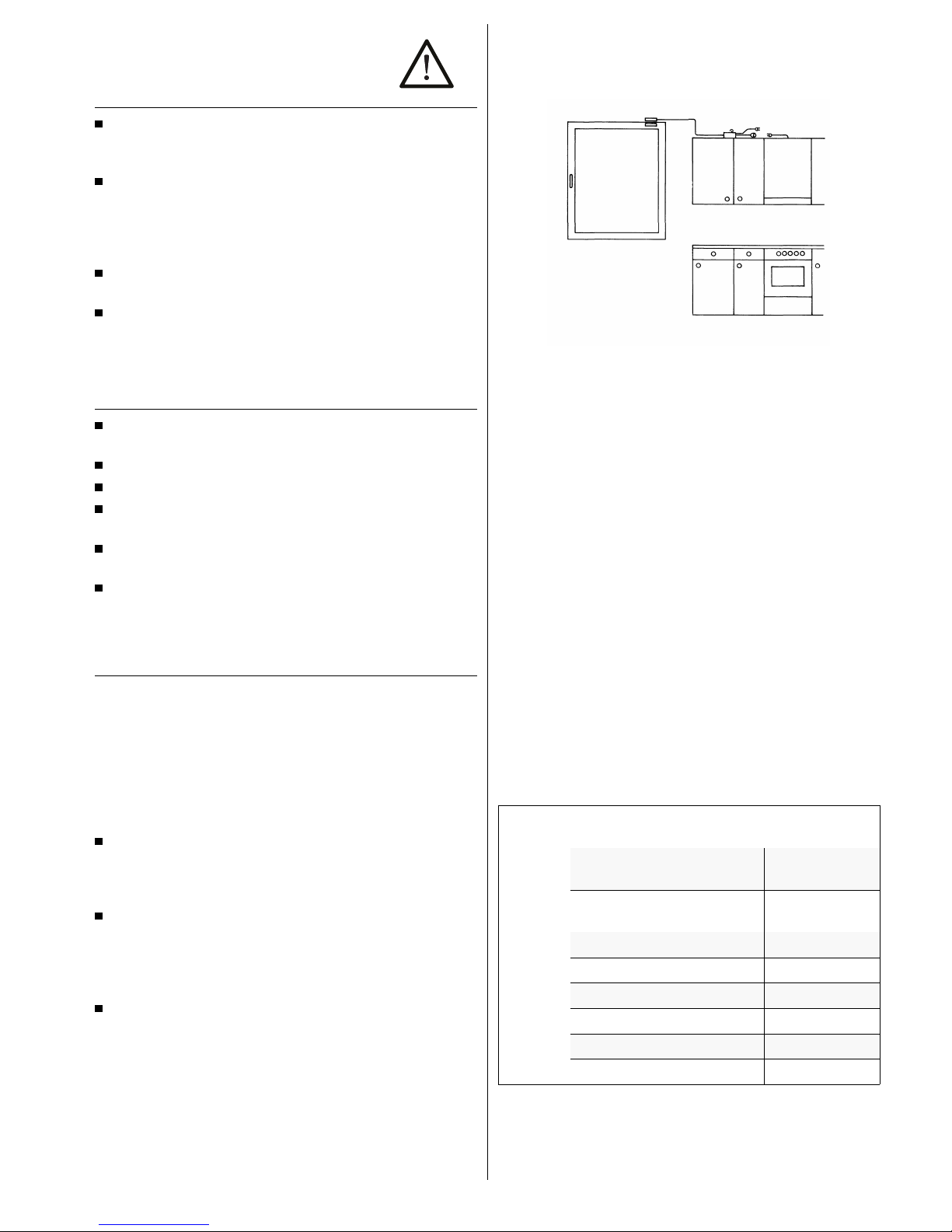
Example of how to use the cooker hood and the stove in complete safety:
A switch at the window prevents the cooker hood from being operated
when the window is closed.
General advice
Remember that the ventilation problem in the kitchen is often not solved merely by installing a cooker hood. For optimum effect and maximum ventilation efficiency the cooker hood requires a sufficient supply of air from the correct sources. Disappointing performance and the development of loud noises are almost always the result of planning or operating errors.
Examples
–
Insufficient supply of fresh air
Result: The speed of the ventilation motor increases, the air capacity decreases and the noises become louder.
Solution: Ensure that there is an adequate supply of fresh air through
structural measures or by opening the window when the cooker hood is
in operation.
–
Saturated filter mats
Result: The air capacity of the cooker hood decreases and the fumes are
insufficiently cleaned.
Solution: Clean the filters regularly before the air capacity decreases.
in extraction mode in recirculation
mode
Appliance Switch on
appliance
on starting cooking on starting cooking
Switch off
appliance
ca. 5 min. after
finishing cooking
ca. 15 min. after
finishing cooking
Position of Door open closed
Window closed open
The room
air is cleaned of
Moisture X —
Heat X —
Fat X X
Odours X X
12 KD 934.1 / KD 634.1

Your appliance at a glance
Using the hood
Please observe the safety instructions on page 12
Before using your appliance for the first time
Please clean the cooker hood before using it for the first time as described
in “Cleaning, care and maintainance”.
Switching the lighting On / Off
The lighting can be used independently of the ventilation.
–
The left hand switch turns the
lighting on.
–
Press again to switch the lighting
off.
Switching on the ventilation
–
Press button 0-1 in order to
switch the hood on.
Changing the ventilation setting
–
You can change the ventilation setting you have selected whenever
you want by pressing a different
ventilation setting button. The ventilation settings are:
0 – 1 = mild
2 = medium
3 = strong
If more than one switch is pressed, the highest setting operates.
Switching the ventilation off
–
Press key 0-1 to switch the
cooker hood off.
upper chimney
lower chimney
control panel
fat filters
hood
ventilation settings
operation indicatorlighting
KD 934.1 / KD634.1 13

Cleaning, care and maintenance
Caution! For repair work or cleaning the inside of the hood,
switch off the household fuse.
Caution! Do not use any scouring agents or aggressive cleaners.
Control panel
–
Carefully wipe the control panel now and again with a soft cloth which is
free of fluff.
Hood
–
Clean the fume trap and the glass shelf with a damp cloth and a little
hand detergent or one of the usual glass cleaning agents.
–
The hood may be cleaned when necessary on the inside with a damp
cloth and hand detergent.
Stainless steel parts
–
Use one of the usual stainless steel cleaning agents from time to time.
Cleaning the metal fat filters
Important: If you use the cooker in recirculation mode, then the two activated carbon filters must be renewed every 6 months. Original filters can be
obtained from your dealer or directly from KÜPPERSBUSCH.
The metal-mesh grease filters should be cleaned after every 30 hours of
operation.
–
Hold each metal-mesh filter by
the handle and push back lightly.
To remove pull down out of the
bracket.
–
Clean the mesh and the grease filters in the dishwasher or wash by hand
with a mild detergent. Rinse well and dry before refitting.
–
In recirculation mode, change the activated carbon filter mat whenever
necessary.
–
To refit the filters, place in the
slot at the rear and push up. They
will then click into place.
Changing the activated charcoal filters (for
recirculation mode)
The activated charcoal filters absorb odours until they are saturated. They
cannot be cleaned or regenerated and have to be replaced with new original replacement filters after 6 months at the latest.
–
Remove and clean all metal-mesh grease filters.
–
Remove the holders and take out
the used activated charcoal filters.
–
Push the longer side of the new
activated carbon filter into the upper runner at the back.
–
Bend the filter mat lightly
downwards and then push into
the upper filter bracket at the
front.
–
Lock in firmly with the holders.
–
Replace the metal-mesh grease
filters.
Replacing a halogen lamp
Caution! The halogen lamps become very hot after being in use
for some time. Therefore, the lamps should be changed when
they have cooled down.
Only replace the halogen lamps with lamps of the same type.
Do not grip the halogen lamps with your bare hands. Finger marks
burn into the lamp glass and reduce the light intensity and service
life of the lamps.
–
Open the light cover.
–
Remove the halogen bulb from its socket.
–
Hold the new bulb (20 watt) with a cloth and push into the socket.
–
Close the light cover.
14 KD 934.1 / KD 634.1

What to do if trouble occurs
Danger! The cooker hood may only be repaired by an authorised
technician.
Danger! For repair work the appliance must be disconnected from
the power supply by pulling out the mains plug or unscrewing the
household fuse.
First check whether there has been any operating error. You can deal with
some problems that occur yourself.
Problem Cause Remedy
It is not possible to
switch off the cooker
hood.
Electronic component is
defective.
Pull out plug or switch off
fuse,
Call Customer Service.
Halogen lighting
does not work.
Lamp defective Replace lamp.
LED does not work. LED defective. Call Customer Service.
Performance of the
cooker hood is reduced.
Filters very clogged. Replace filters.
Rating label
The rating label can be seen when you have removed the fat filter or the
activated charcoal filters. Please make a note of the following data on the
rating label before or while installing the cooker hood in case you have to
consult our Customer Service:
Serial number:
Model designation:
Installation
Danger! The cooker hood may only be installed and the electrics
connected by a qualified technician.
Pay attention to the notes on safety on page 12!
Danger! For all installation and maintenance work the cooker hood
must be disconnected from the power supply. As the mains plug
is no longer accessible after installation, you must switch off the
relevant household fuse.
Scope of delivery
The hood is delivered in a cardboard box. The box contains:
chimney, drill hole template, fixings, activated carbon filter holder, hood with
motor and metal-mesh grease filter
recirculated air deflector (for use only in recirculation mode).
Dimensions for installation
Installation preconditions
Please also observe the notes on extraction paths on page 18.
Walls suitable for mounting
The cooker hood can be mounted directly on the wall or on a steel rear panel.
The fitter is always responsible for selecting the correct fastening material. The fastening method must be suitable for the weight of the hood.
The enclosed dowels and screws are suitable for walls made of perforated bricks or concrete bricks which are 20 mm thick.
For solid concrete walls you must use special concrete dowels from a
specialist store.
For solid wooden walls you must use wood screws of sufficient thickness and length.
KD 934.1
KD 634.1
KD 934.1 / KD634.1 15

Electric connection
The hood is fitted with a normal mains plug and there should therefore be a
socket outlet (230 V AC) near the point of installation.
Recirculation mode
There are no other preconditions for the customer.
Extraction path to the rear
There must be an exhaust channel
150 mm in diameter through the
wall inside the chimney surface.
Extraction path upwards
There must be an exhaust channel
150 mm in diameter inside the chimney surface in the room ceiling above
the installation point of the hood.
Mounting a steel rear panel (optional)
With a telescopic rear panel set the length you want.
–
Mark the drill holes.
–
Drill the holes and insert dowels.
–
Insert the bottom edge of the rear panel behind the worktop or the builtin hob. The rear panel must rest on the worktop.
–
Guide the power cable through the opening in the rear panel and screw
on the panel.
Attaching wall hooks and chimney support
Caution! When the hood is installed, the distance between the
hood and the cooker must be at least 650 mm.
Establish the chimney length accordingly.
The wall mounting must be aligned with a spirit level.
Correct alignment of the hood is only possible if you perform this work
accurately.
If the hood is connected to an exhaust channel, make sure that the exhaust opening is inside the chimney surface and the hood is located centrally above the hob.
The chimney support can be attached to the wall or to the ceiling. The
upper edge of the chimney support corresponds with the upper edge of
the chimney.
–
Place the drill hole template centrally above the hob. The lower edge of
the template corresponds with the lower edge of the hood.
–
Mark the holes for the wall hooks and locking screws.
–
Mark the holes for chimney support centrally above the above the holes
for the wall hooks. For this, the chimney support must held up in the intended position.
–
Drill holes with a ∅ 8 bit and insert wall plugs.
–
Attach the brackets with the wall
screws (B).
–
Release the clamping screws (A).
–
Screw in the chimney support tightly.
–
Remove the metal-mesh grease filter from the hood.
or
16 KD 934.1 / KD 634.1

Fitting the hood
–
Attach the hood to the wall hooks.
–
Align the hood by pushing to left
or right.
–
If necessary, the height at each
wall hook can be altered slightly
with the adjusting screws.
–
Tighten the clamping screws .
–
Tighten the locking screws (C).
Ducting and chimney attachment
After inserting the mains plug, the domestic circuit fuse must be
always removed
–
Remove the transport screws on the chimney sections.
–
Arrange the chimney sections inside one another. For recirculation mode,
the venting slots must be located at the top in the upper section, for extraction mode, they are concealed at the bottom.
–
Recirculation mode only: Screw
the air deflector firmly to the upper chimney section, so that the
deflector openings are in line with
the venting slots. The open side
of the deflector must adjoin the
chimney.
–
The hood and vent opening or air deflector (in recirculation mode) must
be connected via exhaust ducting.
–
Insert the mains plug in the socket.
–
Place the chimney sections in the
hood.
–
Pull out the upper chimney section and screw to the chimney support.
–
Fit the lower chimney section to
the hood.
Fitting the grease filters
Before fitting the filters, find the identification plate and make a note of the
serial number and model and enter it on page 15.
Only for appliances in recirculation mode:
–
Place an activated carbon filter in every filter cover and attach it with the
holders. See “Changing the activated carbon filter” on page 6.
All appliances:
–
Push the metal-mesh grease filter
into the slot at the rear and push
up. It will then click into place.
Recirculation mode
Extraction mode
KD 934.1 / KD634.1 17

Guideline for extraction paths
Use round pipes with a 150 mm diameter or rectangular extraction channels with a cross section of 90 x 220 mm.
You should use the following schematic diagrams as a guide for the extraction paths:
Extraction path through the walls
Here a telescope wall chock which can be adjusted to different wall thicknesses is built into the wall. The exhaust pipe should bend outwards slightly
so that the condensation water can flow away easily.
Extraction through the kitchen ceiling and roof
The height of the exhaust pipe must not exceed 2.5 m. The pipe must be
heat insulated or an air-trap seal must be installed.
Extraction into an existing exhaust shaft
The exhaust air must only be introduced into an existing exhaust shaft if
this is insulated against damp and is not already used for fuel purposes.
Have the chimney sweep responsible approve the use of the shaft.
Please note:
If the extraction channel is led through cold rooms, condensation may
form.
If the extraction channel has several bends, is very long or has a very
small diameter, the suction power can be considerably reduced. The motor may become loud and irregular.
The crucial factor is the correct transition of the exhaust channel into
the chimney:
WRONG!
Correct
Best solution
18
KD 934.1 / KD 634.1
 Loading...