

Bedienungsanleitung
Instructions Booklet
Mode d’emploi
Libretto Istruzioni
Gebruiksaanwijzing
Manual de instrucciones
NL
IT
FR
GB
DE
KD 9650.0 E
ES
14GB
CONTENTS
Dear Customer,
If you follow the recommendations
contained in this Instruction Manual, your
appliance will give you constant high performance and will remain efficient for
many years to come.
RECOMMENDATIONS AND SUGGESTIONS 15
CHARACTERISTICS 16
INSTALLATION 17
USE 20
MAINTENANCE 21
15GB
RECOMMENDATIONS AND SUGGESTIONS
INSTALLATION
• The manufacturer will not be held liable for any damages resulting
from incorrect or improper installation.
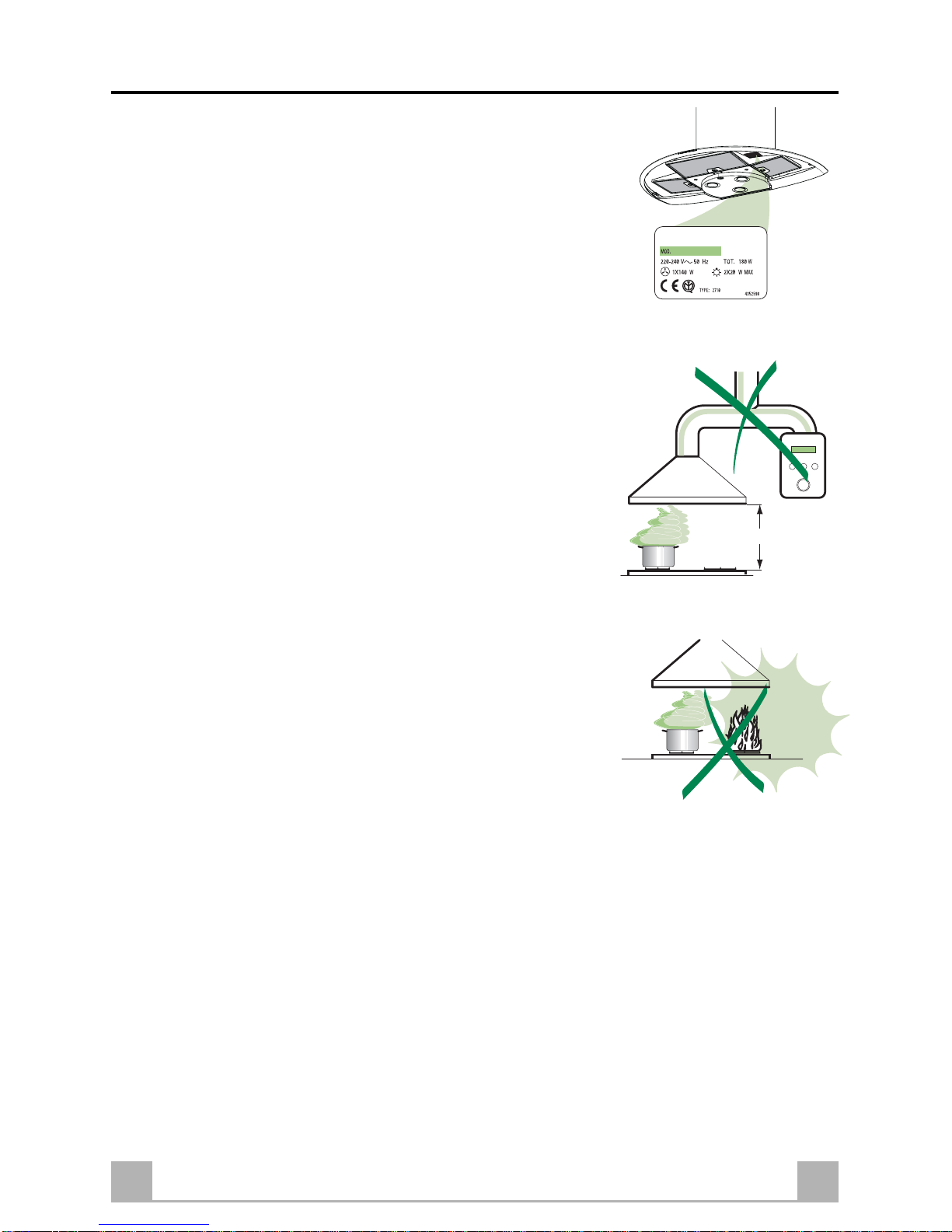
• The minimum safety distance between the cooker top and the
extractor hood is 650 mm.
• Check that the mains voltage corresponds to that indicated on the
rating plate fixed to the inside of the hood.
• For Class I appliances, check that the domestic power supply
guarantees adequate earthing.
Connect the extractor to the exhaust flue through a pipe of minimum
diameter 120 mm. The route of the flue must be as short as possible.
• Do not connect the extractor hood to exhaust ducts carrying
combustion fumes (boilers, fireplaces, etc.).
• If the extractor is used in conjunction with non-electrical appliances
(e.g. gas burning appliances), a sufficient degree of aeration must
be guaranteed in the room in order to prevent the backflow of exhaust
gas. The kitchen must have an opening communicating directly with
the open air in order to guarantee the entry of clean air.
USE
• The extractor hood has been designed exclusively for domestic use
to eliminate kitchen smells.
• Never use the hood for purposes other than for which it has ben
designed.
• Never leave high naked flames under the hood when it is in operation.
• Adjust the flame intensity to direct it onto the bottom of the pan only,
making sure that it does not engulf the sides.
• Deep fat fryers must be continuously monitored during use:
overheated oil can burst into flames.
• The hood should not be used by children or persons not instructed in
its correct use.
MAINTENANCE
• Switch off or unplug the appliance from the mains supply before
carrying out any maintenance work.
• Clean and/or replace the Filters after the specified time period.
• Clean the hood using a damp cloth and a neutral liquid detergent.
650 mm min.
16GB
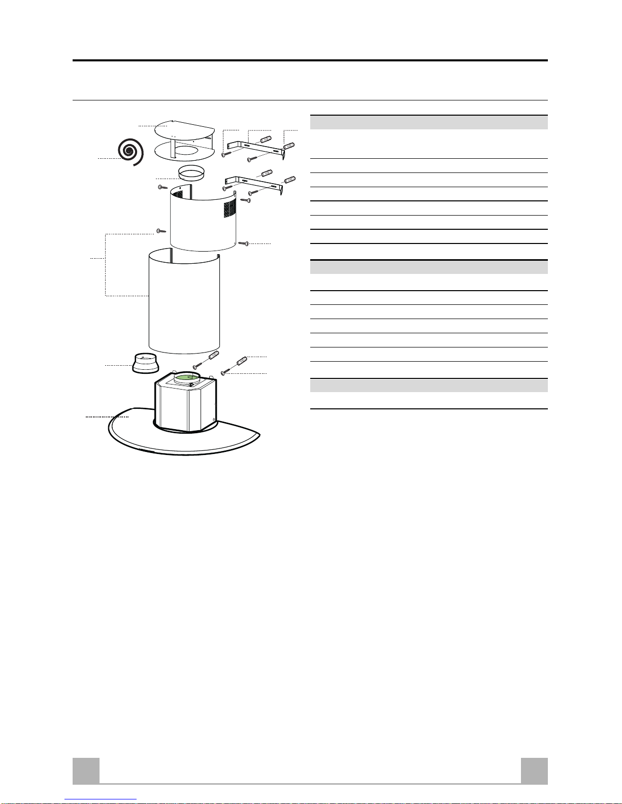
CHARACTERISTICS
Components
Ref. Q.ty Product Components
1 1 Hood Body , complete with: Controls, Light, Blower,
Filters
2 1 Telescopic Chimney comprising:
2.1 1 Upper Section
2.2 1 Lower Section
8 1 Directional Air Outlet grille
9 1 Reducer Flange ø 150-120 mm
10 1 Flange ø 150 mm
Ref. Q.ty Installation Components
7.2.1 2 Upper Chimney Section Fixing Brackets
7.4 1 Air Outlet Connection
11 8 Wall Plugs
12a 8 Screws 4,2 x 44,4
12c 6 Screws 2,9 x 6,5
13 1 Gasket
Q.ty Documentation
1 Instruction Manual
2.1
2.2
2
1
11
12a
12c
12a
7.2.1 11
9
10
7.4
13

17GB
INSTALLATION
Wall drilling and bracket fixing
W all marking:
• Draw a vertical line on the supporting wall up to the ceiling, or as high as practical, at the centre of
the area in which the hood will be installed.
• Draw a horizontal line at 650 mm above the hob.
• Place bracket 7.2.1 on the wall as shown about 1-2 mm from the ceiling or upper limit aligning the
centre (notch) with the vertical reference line.
• Mark the wall at the centres of the holes in the bracket.
• Place bracket 7.2.1 on the wall as shown at X mm below the first bracket (X = height of the upper
chimney section supplied), aligning the centre (notch) with the vertical line.
• Mark the wall at the centres of the holes in the bracket.
• Mark a reference point as indicated at 116 mm from the vertical reference line and 335 mm above
the horizontal reference line.
• Repeat this operation on the other side.
• Drill ø 8 mm holes at all the centre points marked.
• Insert the wall plugs 11 in the holes.
• Fix the brackets using the 12a screws (4,2 x 44,4) supplied.
• Insert the two screws 12a (4,2 x 44,4) supplied in the hood body fixing holes, leaving a gap of 5-6
mm between the wall and the head of the screw .
11
12a
335
X
116
1
÷
2
116
650 min.
7.2.1

18GB
12a
Vr
9
ø 120ø 150
Mounting the hood body
• Before attaching the hood body , tighten the two
screws Vr located on the hood body mounting
points.
• Hook the hood body onto the screws 12a
• Fully tighten support screws 12a
• Adjust screws Vr to level the hood body .
Connections
DUCTED VERSION AIR EXHAUST SYSTEM
When installing the ducted version, connect the hood to the chimney using either a flexible or rigid pipe
ø 150 or 120 mm, the choice of which is left to the installer.
• T o install a ø 120 mm air exhaust connection,
insert the reducer flange 9 on the hood body
outlet.
• Fix the pipe in position using sufficient pipe clamps
(not supplied).
• Remove any activated charcoal filters.
RECIRCULATION VERSION AIR OUTLET
• Lean the air outlet junction 7.4 against the wall and place
it under the upper fixing bracket 7.2.1 centring it to the
vertical reference line.
• Mark the centre of the fixing slots.
• Drill ø 8 the marked points.
• Put the dowels 11 into the holes.
• Fix the flange 10 to the lower opening of the junction
piece 7.4.
• Fix the junction piece to the wall using the 2 screws 12a
(4,2x44,4) (supplied).
• Cut the gasket 13 into two pieces of same size and place
them to the round shaped part of the junction piece.
• Connect the hood air outlet to the flange in the lower part
of the junction using a rigid or flexible ø 150 tube (by
installer's choice).
7.4
7.2.1
10
13

19GB
ELECTRICAL CONNECTION
• Connect the hood to the mains through a two-pole switch
having a contact gap of at least 3 mm.
• Open the lighting unit by turning the knob provided.
• Ensure that the supply cable connector is properly inserted into the Suction device socket
Flue assembly
Upper exhaust flue
• Slightly widen the two sides of the upper flue
and hook them behind the brackets 7.2.1, making
sure that they are well seated.
• Secure the sides to the brackets using the 4
screws 12c (2,9 x 9,5) supplied.
Lower exhaust flue
• Open the two side flaps of the Chimney stack
slightly, hook them between the upper Chimney
stack and the wall, and close them again until they
fit into place, fastening the lower part of the chimney stack into the hood canopy .
12c
7.2.1
2.1
2.2
2
12c

20GB
USE
Control panel
BUTTON LED FUNCTIONS
L - Turns the lighting system on and off.
T1 0/1 Motor Fixed Turns the motor on and off.
Flashing 24h Exchange
Enabled by pressing and holding the button for approx. 3”.
Provides 100 m3/h suction with a noise level of just 28dB(A).
T o disable, press the button again and hold for approx. 3”.
T2 Speed Decreases the working speed.
Flashing Delay (30’)
Press and hold the button for approx. 2” to enable a 30’ automatic delayed shutdown. Suitable to complete elimination of
any residual fumes.
T3 Speed Increases the working speed.
T4 Speed Fixed Intensive speed.
Suitable to deal with maximum vapour emission, this turns off
automatically ten minutes after starting operation. It can be
disabled by pressing the button T4.
Flashing POWER function (maximum suction power)
Press T4 for approximately 3 seconds to enable the Power
function (maximum suction power), which is indicated by
flashing of the LED. This function will be revert to intensive
speed after 5 minutes or when T4 is pressed again.
S1 Led Fixed Signals triggering of the Metal Grease Filters saturation alarm,
indicating that the filters need washing. The alarm is triggered after the Hood has been operating for 100 working
hours. (Reset see paragraph on Maintenance)
Flashing When enabled, signals triggering of the Activated Charcoal
Filter, which must be replaced; the Metal Grease Filters must
also be washed. The Activated Charcoal Filter saturation
alarm is triggered after the Hood has been operating for 200
working hours. (Enabling and Reset see paragraph on
Maintenance)
I/P
resetdelay
T1
T2 T3 T4
S1
L

21GB
REMOTE CONTROL (OPTIONAL)
The appliance can be controlled using a remote
control powered by a 1.5 V carbon-zinc alkaline
batteries of the standard LR03-AAA type.
• Do not place the remote control near to heat
sources.
• Used batteries must be disposed of in the proper
manner .
MAINTENANCE
Cleaning the Comfort Panels
• Open the Comfort Panel using the knobs
provided.
• Disconnect the panel from the hood canopy by
sliding the fixing pin lever .
• The comfort panel must never be washed in a
dishwasher .
• Clean the outside using a damp cloth and neutral
liquid detergent.
• Clean the inside as well using a damp cloth and
neutral detergent; do not use wet cloths or
sponges, or jets of water; do not use abrasive
substances.
• When the above operation has been completed,
hook the panel back to the hood canopy and
close it by turning the knob in the opposite
direction.

22GB
Grease filters
Alarm signal reset
• Turn the Lights and the suction Motor off, and disable the 24h function if it has been enabled.
• Press T3 for at least 3 seconds, until indicators flash to confirm.
Cleaning the filters
• The filters must be cleaned every 2 months of
operation, or more frequently for particularly
heavy usage, and can be washed in a dishwasher.
• Open the Comfort Panel using the knobs provided.
• Remove the filters one at a time by pushing them
towards the back of the group and pulling down
at the same time.
• W ash the Filters without bending them, and leave
them to dry thoroughly before replacing. ( The
surface of the filter may change colour after a
time, but this has absolutely no effect on its
efficiency.)
• When refitting the filters, make sure that the
handle is visible on the outside.
• Close the comfort panel.
Activated charcoal filter (Recirculation version)
• The filter is not washable and cannot be regenerated. It must be replaced when led S1 flashes or at
least every 4 months. The alarm signal will only light up when the extractor motor is switched on.
Alarm signal activation
• In Recirculation version Hoods, the Filter saturation alarm can be enabled on installation or at a later
date.
• Turn the Lights and the suction Motor off.
• Press and hold the T3 button for at least 10 seconds, until the LEDs start to flash. Note the number
of flashes:
- 2 flashes of the LED Activated charcoal filter saturation alarm ENABLED.
- 1 flash of the LED Activated charcoal filter saturation alarm DISABLED;

23GB
Alarm signal reset
• Turn the Lights and the suction Motor off, and
disable the 24h function if it has been enabled.
• Press T3 for at least 3 seconds, until the LEDs
flash in confirmation.
Replacing the Filter
• Open the lighting unit by turning the knob
provided.
• Remove the saturated activated carbon filter by
releasing the fixing hooks
• Fit the new filter by hooking it into its seating
• Replace the lighting unit.
Lighting
LIGHT REPLACEMENT
20 W halogen light.
• Extract the lamp from the lamp holder by pulling
gently .
• Replace with another of the same type, making
sure that the two pins are properly inserted in the
lamp holder socket holes.
 Loading...