

GB
F
NL
I
E
BEDIENUNGSANWEISUNG
mit Montageanweisungen
Instructions for use and installation instructions
Instructions d’ utilisation et avis de montage
Gebruiksaanwijzing en montagehandleiding
Istruzioni di uso e di montaggio
Instrucciones de uso y de montaje
IKDEM 976.1GE
IKD 976.1GE
15
Part 1 - INSTALLATION INSTRUCTIONS
1 - GENERAL INFORMATION
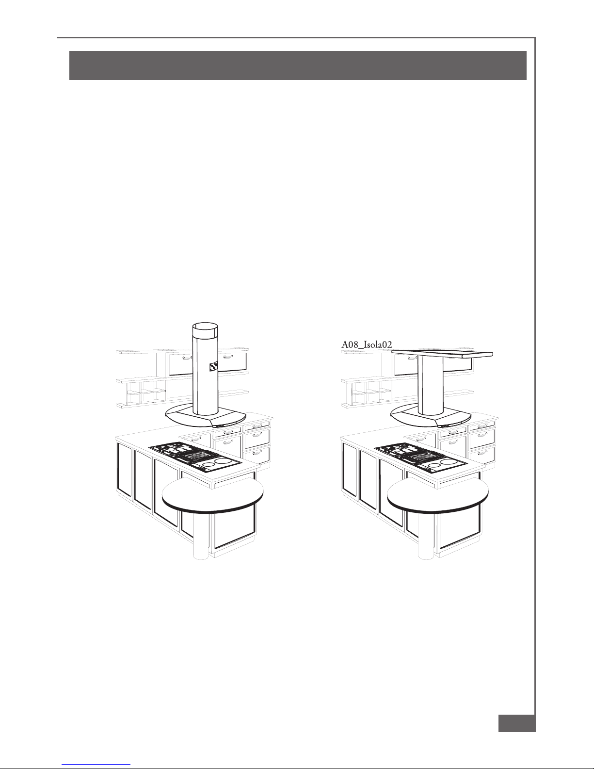
This hood is designed for installation over a cooking appliance fitted into a peninsular
or island kitchen cabinet. The hood can be fixed to the ceiling or to a wooden buttress
(fig. 2). The hood is supplied complete with a substantial ceiling fixing system which
is fully adjustable in height to suit most installation requirements. This canopy hood
is designed to be used either in the extraction mode (ducted to the outside) or in the
recirculation mode (internal recycling). Before commencing the installation,
consideration should be given to the difficulties to be found during installation
and to the bulky weight of the hood. The installation work must be undertaken
by a qualified and competent person in conformity to the rules concerning the
evacuation of contaminated air. The manufacturer disclaims all liability for any
damage or injury caused as a result of not following the instructions for
installation contained in the following text.
2
ab
16
Part 1 - INSTALLATION INSTRUCTIONS
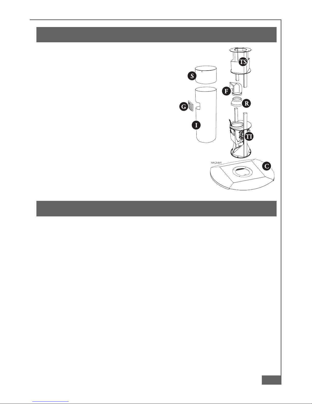
2 - COMPONENTS
The cooker hood is made up of the following
components (fig. 1):
2.1 - no. 1 canopy item “C”, including controls,
worktop illumination and fan unit
2.2 - no. 1 telescopic frame consisting of:
no. 1 upper frame “TS”
no. 1 lower frame “TI”
2.3 - no. 1 telescopic chimney stack formed by:
no. 1 upper section item “S”
no. 1 lower section item “I”
no. 1 bag of screws and accessories
no. 1 recirculation venting grille item “G”
2.4 - no. 1 recirculation spigot item “F”
2.5 - no. 1 reduction flange Ø 150-200 item “R”
3 - SAFETY WARNINGS
3.1 - The cooker hood ducting must not be connected to a flue which is used for exhausting
fumes from appliances supplied with energy other than electric such as a central heating
flue or water heating flue.
3.2 - Ensure that the mains voltage corresponds with the voltage on the rating plate inside
the hood.
3.3 - Connect the cooker hood to the mains via a double pole switch which has 3 mm
clearance between the contacts.
3.4 - The appliance must be earthed.
3.5 - The hood must be positioned at least 65 cm above a cooking appliance.
3.6 - Never do flambé cooking under this cooker hood.
3.7 - Never leave frying pans unattended during use as overheated fats and oils may catch
fire.
3.8 - Before carring out any kind of maintenance or cleaning, disconnect the hood from the
mains supply.
3.9 - If the room where the cooker hood is to be used contains a fuel burning appliance such
as a central heating boiler, ensure that there is an adequate supply of air into the room.
When the cooker hood is used in conjunction with other appliances supplied with
energy other than electric, the negative pressure in the room must not exceed 0,04
mbar to prevent fumes being drawn back into the room by the cooker hood.
1

17
Part 1 - INSTALLATION INSTRUCTIONS
4 - INSTALLATION
To install the hood proceed by fitting the components in
the following order:
4.1 - Fitting of upper telescopic frame “TS”
4.2 - Fitting of lower telescopic frame “TI”
4.3 - Setting the hood for recirculation or evacuation
4.4 - Connection to the mains supply
4.5 - Fitting the chimney
4.6 - Fitting the canopy
4.7 - Electrical connection of controls and functional test
4.1 - Fitting of upper telescopic frame
“TS”
The frame is suitable for fixing to the ceiling as illustrated
in (2A) or to a wooden buttress (2B) of adequate thickness
and well secured to the ceiling or other carrying structure.
Remember that the recycled air can be directed in four
different directions: such choice must be made when
securing the upper frame (see point “d”).
a) Separate the lower frame “TI” (6C) from the upper part
“6A” by loosening the four retaining screws “6B” with the
socket head screw wrench provided “6D”.
b) Remove the screws “3A” and pull out the upper pipe “S”(3B)
of the telescopic chimney.
c) Using a plumb line or similar tool, mark the centre on the
ceiling or buttress from the centre of the cooking appliance.
d) (fig. 5) Use the drilling template “5A” provided to mark the
centre on the ceiling or wooden buttress and align one of
the two axes (A or B) of the template parallel with the long
side of the hob “5C” bearing in mind in which direction you
want the filtered air to exit. Vent direction 1 or 2, as indicated
on the template, is determined during the subsequent fitting
phase of the lower frame (paragr. 4.2). Mark the position of
the 4 holes on the template, plus the power cable hole.
e) Position “5E” indicates the useful area to pass the mains
cable.
f ) Drill the holes as follows:
- ceiling: 4 holes Ø 10 mm for securing the upper frame
1 hole Ø 10 mm to pass the mains cable
- buttress: 4 holes Ø 8 mm for securing the upper frame
1 hole Ø10 mm to pass the mains cable.
5
6

18
Part 1 - INSTALLATION INSTRUCTIONS
g) For extraction mode with ceiling vent only
Use the template provided to mark the ø 125 mm hole on the
ceiling for ducting when the range hood is to be installed in the
extraction mode.
h) Fitting the hood to the ceiling
Attention: Due to the many differing types of ceiling construction,
the choice of fixings is left to the discretion of the installer. It is
necessary to emphasise that the fitting has to be absolutely
accurate because of the weight of the cooker hood and bacause of the flexing caused
by accidental lateral stresses on the appliance. Only the following types of ceiling
are suitable for installing the island cooker hood:
1- Solid concrete ceiling: use dowels for concrete (not supplied).
2- Solid wooden buttress ceiling: use Ø 10 mm wood screws with a minimum length
of 120 mm (not supplied).
3- Cavity ceiling with inner empty space, having a thickness of about 20 mm: use,
in this case, the four dowels and screws supplied. Once fixed, make sure that the
basis is absolutely stable even when the metal frame is subjected to lateral stresses.
4 - If the ceiling is not strong enough in the area where the hood is to be fixed, the
installer must strengthen the area adequately so that it can withstand the weight of
the hood.
i) When fitting the hood to a wooden buttress: secure the frame to the base of the
buttress using the four M6 x 80 mm nuts and bolts provided.
4.2 - Fitting the lower telescopic frame “TI”
a) Turn the lower telescopic frame “TI” (6C) according to the
chosen direction of filtered air vent: “6U” or rotating the
frame “6C” in the opposite direction.
b) Connect the lower frame “TI” (6C) to the upper frame “TS”
(6A) and secure by tightening the 4 screws “6B” using
the socket head screw wrench provided “6D”, adjusting
the height from the hob and bearing in mind that the
canopy item to be fitted subsequently is 7 cm high. In any
event, in this position, the lower part of the frame must
not be positioned at less than 72 cm from the underlying
hob.
6
3

19
Part 1 - INSTALLATION INSTRUCTIONS
4.3 - Setting the hood for evacuation or recirculation
1 - Setting for evacuation:
a) Apply the reducing spigot “7B” to the
upper part of the extraction unit “7D”.
b) Connect spigot “7B” to the external
ducting by means of rigid or flexible duct
“7G” (not provided) to be fixed using
clamps “7F” provided.
c) Remove any charcoal filter in the lower
part of the canopy (see paragr. 3.2 - part
two).
2 - Setting for recirculation:
a) Apply the reducing spigot “7B” to the
upper part of the extraction unit “7D”.
b) Fit the recycling spigot “7A” to the
reducing spigot “7B”, directing it in the
position chosen for air evacuation.
c) Fit the charcoal filter inside the canopy
(see paragr. 3.2 - part two) after power
connections have been done (paragr.
4.7).
4.4 - Electrical connection
a) Always carefully follow all instructions in paragr. 3 concerning safety.
b) Connection to mains supply must be done by passing the power cable through the
centre hole of the frame.
c) Connect the mains cable to the mains supply.
4.5 - Fitting the chimney
a) Insert the upper pipe “S” (4B) of the telescopic chimney and
secure with the two screws “3A”.
b) Insert the lower pipe “I” (4C) of the telescopic chimney,
positioning it so that opening “4D”, in the event of evacuation
fitting, is aligned with the recircualtion spigot “7A”. Note: Do
not fit the small directional grille “G”. This operation must be
done after installation of the canopy “C”. Support pipe “4C”
with one hand to allow subsequent fitting of the canopy item.
7
A08_Isola04
A
B
C
D
G
4

20
Part 1 - INSTALLATION INSTRUCTIONS
4.6 - Fitting the canopy
a) Remove the three grease filters “8D” by
applying pressure to the handles “8E”.
b) If fitted, remove the charcoal filter “8C”.
c) Position the canopy item “8A” in line with
the holes of lower frame “TI” and secure
with 4 screws “8B”. Note: No further
operation must be carried out without
having tightened the 4 screws “8C”.
During this operation, until at least one
screw “8C” has been tightened, slightly
support the canopy item to avoid
accidental movement.
d) Fit the directional grille “4E” in slot “4D”.
4.7 - Electrical connections
a) Remove cover “9B” by removing the two
screws “9A”.
b) Remove connector “9D” and connect it to “9E” from the
motor assembly.
c) Refit the cover “9B” paying attention that the connector cable
is correctly positioned in slot “9C”.
d) Once all the connections have been done, check correct
operation of:
- LIGHTS
- MOTOR START
- SPEED CHANGE
A08_Isola04
A
B
C
D
G
4
8
D
E
B
A
A
A08_Isola09
B
C
9

21
Part 2 - USE AND MAINTENANCE INSTRUCTIONS
1 - SAFETY WARNINGS
It is most important that all the warnings shown in paragraph 3 of the Installation
Instructions are strictly observed. Moreover, pay special attention to the following
warnings during the use and maintenance of the cooker hood:
1.1 - The grease filters and the charcoal filter should be cleaned or replaced as recommended
by the manufacturer or more frequently if the hood is used consistently over 4 hours
per day.
1.2 - When using a gas hob in connection with the cooker hood never leave the burners of
the hob uncovered while the hood is in use or when the pans have been removed.
Switch off the gas before removing the pan, or for just short periods and never leave
the hob unattended.
1.3 - Always ensure that the flame is kept at the correct intensity to prevent the flame from
licking round from the bottom of the pan: this will save energy and will avoid a dangerous
concentration of heat.
1.4 - Always ensure that the appliance is used in accordance with the manufacturer’s
instructions for the removal of contaminated air and odours during cooking.
2 - OPERATION
Control Panel (fig. 10)
The layout of the control panel is as follows:
Key = Turns the lighting system on and off
Key = Turns the motor on and off
Key = Decreases the working speed
Key = Increases the working speed
Key = Intensive speed with timed stoppage. Suitable to deal with maximum
vapour emission, this turns off automatically 10 minutes after starting
operation. It can be
disabled by
pressing the key .
3 - MAINTENANCE
Constant maintenance guarantees proper operation and long-term reliability.
Particular attention should be paid to the metal grease filters and, for recirculation
hoods only, to the activated charcoal filters. The appliance is equipped with a system
that indicates automatically when it is time to carry out maintenance operations.

22
Part 2 - USE AND MAINTENANCE INSTRUCTIONS
3.1 - Metal grease filters
1 - Cleaning
These filters must be washed when LED 0/1 Motor starts to flash, or at
the most once every 2 months, using a normal household detergent;
their compact size also enables them to be washed in a dishwasher.
2 - Removing the filters:
a) Remove the filters “8D” (one at a time)
by means of handles “8E”, pushing these
towards the rear part of the hood and at
the same time pulling downwards.
b) Refit the filters, keeping the handle in a
visible and front position.
3 - Enabling the alarm signal
The hood is already set up to trigger an
alarm indicating saturation of the metal
grease filters, so this function does not
need to be enabled.
4 - Resetting the alarm signal
To turn the alarm signal off, proceed as
follows:
- Turn off the lights and the suction motor;
- Press the Speed + button for at least 3
seconds, until the LEDs flash in
confirmation. In any case the saturated
filters alarm will only come into operation when the suction motor is turned on.
WARNING: always comply with the maintenance and replacement times
indicated, in order to avoid a possible risk of fire when the filters are saturated
with grease.
3.2 - Activated charcoal filter
1 - Operation
The activated charcoal filter is only fitted in recirculation type hoods. It
will retain odours until it becomes saturated. It cannot be washed or
regenerated, and must be replaced when the Intensive Speed LED
starts to flash, or at least once every 4 months of use. Attention: in
recirculation type hoods the 0/1 Motor LED may start to flash as well as the Speed
+ LED. This indicates that as well as replacing the activated charcoal filter, it is also
necessary to perform maintenance operations on the metal grease filters (see
paragraph 3.1).
8

23
Part 2 - USE AND MAINTENANCE INSTRUCTIONS
2 - Replacement
Remove the antigrease filters “8D”
and the activated carbon filter
“11A” from its seat by acting on
the hooks. Fit the new activated
carbon filter and the metal
antigrease filters.
3 - Enabling the alarm signal
In recirculation type hoods the
saturated filters alarm must be
enabled as indicated below:
- Turn off the lights and the suction motor;
- Press and hold the Speed + button for at least 10 seconds, until the LEDs start to
flash. Note the number of flashes:
- 2 flashes of the LED Activated charcoal filter saturation alarm ENABLED.
- 1 flash of the LED Activated charcoal filter saturation alarm DISABLED;
4 - Resetting the alarm signal
To turn the alarm signal off, proceed as follows:
- Press the Speed + button for at least 3 seconds, until the LEDs flash in confirmation.
In any case the saturated filters alarm will only come into operation when the suction
motor is turned on.
WARNING: always comply with the maintenance and replacement times
indicated, in order to avoid a possible risk of fire when the filters are saturated
with grease.
3.3 - Lighting
This consists of four 20 W halogen lamps.
To replace, proceed as follows (fig. 12):
a) Remove the two screws “12B”.
b) Raise the retaining ring “12A”.
c) Remove the lamp “12C” and replace with
another having the same characteristics.
3.4 - Cleaning
When cleaning the hood:
- Never use a wet cloth or sponge, or
running water.
- Never use thinners or products containing alcohol, as they might damage the
paintwork.
- Never use abrasive cleaning materials, in particular when cleaning stainless steel
surfaces.
It is recommended to use a damp cloth and mild liquid household cleaner.
11
12
 Loading...