

Küppersbusch IKD9350.0, IKD12350.0, IKDEM9350.0, IKDEM12350.0 Instructions For Use And Installation Instructions
IKD9350.0-IKD12350.0
IKDEM9350.0-IKDEM12350.0
BEDIENUNGSANWEISUNG
mit Montageanweisungen
GB
Instructions for use and installation instructions
Instructions d'utilisation et avis de montage
Gebruiksaanwijzing en montagehandleiding
Istruzioni di uso e di montaggio
Instrucciones de uso y de montaje
Instruções de uso e de montagem
F
NL
I
E
P
ENGLISH
WARNING
The distance between the supporting surface for the cooking vessels on the hob and the lower part of the hood must
be at least 65 cm. If the instructions for installation for the hob specify a greater distance, this has to be taken into
account.
The air collected must not be conveyed into a duct used to blow off smokes from appliances fed with an energy other
than electricity (central heating systems, thermosiphons, water-heaters, etc.).
Comply with the official instructions provided by the competent authorities in merit when installing the disposal duct.
In addition, exhaust air should not be discharged into a wall cavity, unless the cavity is designed for that purpose.
The room must be well aerated in case a hood and some other heat equipment fed with an energy other than electricity
(gas, oil, coal heaters, etc) operate at the same time.
In fact the intake hood, disposing of air, could create a vacuum in the room. The vacuum should not exceed 0,04mbar.
This prevents the gas exhausted by the heat source from being intaken again. It is therefore advisable to ensure
the room contains air taps able to ensure a steady flow of fresh air.
Check the data label inside the appliance; if the symbol ( ) is printed, read the following: this appliance has
such technical particulars that it belongs to class II insulation, therefore it must not be earthed.
The following warning is valid in the United Kingdom only: in case your cable is not furnished with a plug, read the
following instructions; as the colours of the wires in the mains lead of this appliance may not correspond with the
coloured markings identifying the terminals in your plug, proceed as follows: – the wire which is coloured blue must
be connected to the terminal which is marked with the letter N or coloured black; – the wire which is coloured brown
must be connected to the terminal which is marked with the letter L or coloured red. – terminal of a three-pin plug.
Check the data label inside the appliance; if the symbol ( ) is NOT printed, read the following: ATTENTION:
This appliance must be earthed. When making the electrical connections, check that the current socket has a ground
connection.
The following warning is valid in the United Kingdom only: in case your cable is not furnished with a plug, read the
following instructions; as the colours of the wires in the mains lead of this appliance may not correspond with the
coloured markings identifying the terminals in your plug, proceed as follows:
– the wire which is coloured green and yellow must be connected to the terminal in the plug which is marked with the
letter E or by the earth symbol [
], or coloured green or green and yellow; – the wire which is coloured blue must
be connected to the terminal which is marked with the letter N or coloured black; – the wire which is coloured brown
must be connected to the terminal which is marked with the letter L or coloured red.
When making the electrical connections, check that the voltage values correspond to those indicated on the data
plate inside the appliance itself. In case your appliance is not furnished with a non separating flexible cable and has
no plug, or has not got any other device ensuring omnipolar disconnection from the electricity main, with a contact
opening distance of at least 3 mm, such separating device ensuring disconnection from the main must be included
in the fixed installation. If your unit features a power lead and plug, position this so the plug is accessible.
Always switch off the electricity supply before carrying out any cleaning or servicing operations on the appliance.
USE
Avoid using materials which could cause spurts of flame (flambées) near the appliance.
When frying, take particular care to prevent oil and grease from catching fire. Already used oil is especially dangerous
in this respect. Do not use uncovered electric grates.
To avoid possible risks of fire always comply with the indicated instructions when cleaning anti-grease filters and
when removing grease deposits from the appliance.
MAINTENANCE
Thorough servicing guarantees correct and long-lasting operation.
Any fat deposits should be removed from the appliance periodically depending on amount of use (at least every 2
months). Avoid using abrasive or corrosive products. To clean painted appliances on the outside, use a cloth dipped
in lukewarm water and neutral detergent. To clean steel, copper or brass appliances on the outside, it is always best
to use specific products, following the instructions on the products themselves. To clean the inside of the appliance,
use a cloth (or brush) dipped in denatured ethyl alcohol.
DESCRIPTION
This appliance is equipped with a completely automatic system (Advanced Sensor Control) capable to manage
all the functions of your hood. Thanks to the ASC, the air in the kitchen is costantly clean and odour free
without any manual intervention. The advanced sensor catches all sort of vapours, smokes and odours caused
by the cooking process. The ASC also captures an abnormal presence of GAS.
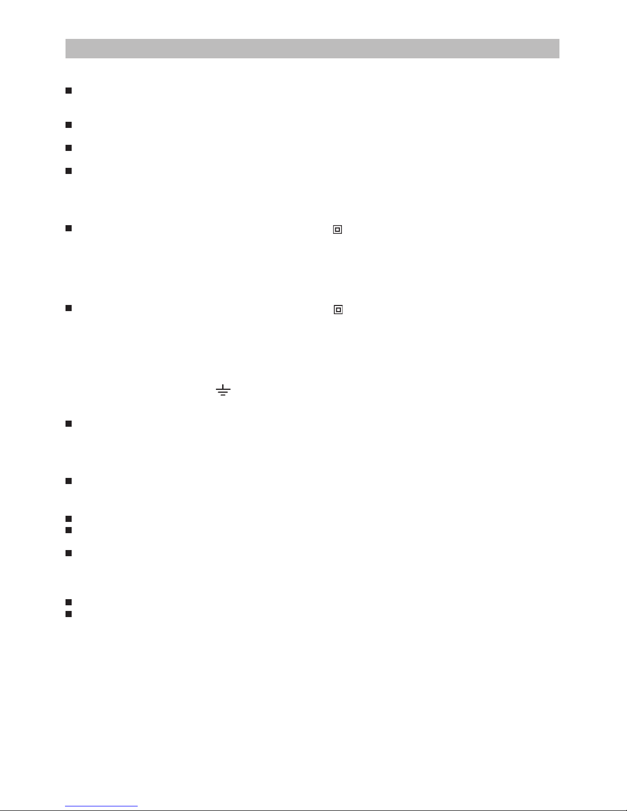
The unit can be found in filtering hoods, ducting hoods or in hoods with an outside motor. In the Filtering
version the air and the kitchen fumes that are conveyed by the apparatus are depurated by the charcoal filter

and put back into the room through the small grilles of the ventilation flue (Fig. 1). ATTENTION: When using the
filtering version, a charcoal filter and an air baffle (Fig. 1A) must be used, which placed at the top of the structure,
allows the air to recycle back into the room. In the Ducting version, cooking vapours and odours are conveyed
straight outside by a disposal duct which passes through the ceiling (Fig. 2). In the hoods with an outside motor
(Fig. 3), a vacuum suction unit must be connected; this exhaust will operate separately, conveying the exhaust
air through the unit. Only use vacuum units suggested in the original catalogue.
INSTALLATION
ATTENTION: Three people are required for proper installation; the unit should be installed by a qualified operator.
Also follow carefully each step of the assembly instructions, and once installation has been completed, make sure
that the hood is firmly secured in place.
To facilitate installation, before starting remove the grease filters: press inward on the clamp at the handle and pull
the filter downward (Fig. 4).
For assembling it is essential to: – Prepare the connection to the mains within the telescopic flue. – If your unit is
installed in a ducting hood or in a hood with outside motor, prepare the air exhaust hole.
When installing ducting hoods and hoods with external motor, to achieve the best possible conditions use an air exhaust
pipe that : is as short as possible, has a minimum of curves (maximum angle: 90°), is made of a material that complies
with the standards (which vary from nation to nation) and is smooth on the inside. It is also advisable to avoid any drastic
changes in pipe section (diameter: 150 mm).
ASSEMBLING - Using the special drilling template, drill the holes for fixing to the ceiling on the vertical side of your
hob. Carefully observe all the indications for final positioning of the apparatus. Take into account that one of the template
axes must correspond to the axis of the hood controls. Fix the bracket to the ceiling using the screws and screw anchors
provided (Fig. 5). Be careful, because the position of the bracket determines the final position of the apparatus: the side
with the slot B corresponds to the side opposite the commands. Assemble the plate of the electrical system fixing it with
2 screws and 2 metal washers (Fig. 6).
Ducting version and version with an external motor: Fix the telescopic structure to the bracket by means of 4 screws
(provided), running the air evacuation pipe through the telescopic structure and the electric power cable through the special
hole in the bracket (Fig. 7). Adjust the height of the telescopic structure by means of the four retaining screws C (Fig.
8), taking into account that the height of the hood is 80 mm and that the distance between the hood and the hob must
be at least 650 mm (Fig. 9). Take the upper pipe (with the round slots) and fit it on the telescopic structure with the slots
facing downwards; fit the pipe to the bracket with 2 screws (Fig. 10). Take the lower pipe and fit it in the same manner
as before; slide it to the top and stop it in that position using a screw inserted in the hole of the upper pipe as a catch
(Fig. 11).
Take the flange with the metal valve (Fig. 12H) and assemble it onto the opening of the hood for air venting, pressing slightly.
Fit the hood to the telescopic structure by means of 4 screws (provided) – Fig. 13.
Through openings D (Fig. 13) fix the air evacuation pipe to flange H.
Only for models with external motor (Fig. 14): connect the hood to the external motor using the special terminal block:
remove wire clamp A and lid B from the wiring junction box; fix the connecting wire of the external motor to terminal C;
then replace wire clamp A and lid B on the wiring junction box; the other end of the wire is secured to the terminal block
on the external motor.
Make the electrical connection by means of the power cable. Remove the screw used as catch and slide the lower pipe
downwards, placing it gently on the apparatus. Installation is now complete and the anti-grease filters can be reassembled.
Filtering version: Fix the telescopic structure to the bracket by means of 4 screws (provided), running the electric power
cable through the special hole in the bracket (Fig. 7). Adjust the height of the telescopic structure by means of the four
retaining screws C (Fig. 8), taking into account that the height of the hood is 80 mm and that the distance between the
hood and the hob must be at least 650 mm (Fig. 9). Insert the air baffle (F) in the structure (Fig.15). Through the openings
E (Fig.16), fit the flange (G) to the baffle (F) locking it with a turning movement. Fix a flexible pipe to the flange (G) for
air evacuation (Fig. 16). Take the upper pipe (with the round slots) and fit it on the telescopic structure with the slots facing
upwards; fit the pipe to the bracket with 2 screws (Fig. 17). Take the lower pipe and fit it in the same manner as before;
slide it to the top and stop it in that position using a screw inserted in the hole of the upper pipe as a catch (Fig. 11).
Take the reduction (Fig. 18L) and assemble it onto the air venting opening of the hood, pressing slightly.
Fit the hood to the telescopic structure by means of 4 screws (provided) – Fig. 19.
Fix the air evacuation pipe onto the reduction (L).
Make the electrical connection by means of the power cable. Remove the screw used as catch and slide the lower
pipe downwards, placing it gently on the apparatus. Install the charcoal filter clipping the 2 filter clips into place
(Fig.20) and turn the filter upwards. Installation is now complete and the anti-grease filters can be reassembled.

OPERATION
Controls:
See Figure 21.
Key A : switches the lights on/off. Key B : enables/disables “Automatic” function. When this
function is selected, an “A” appears on the display C, and the speed of the motor increases or decreases
depending on the smoke, odours and gas present in the kitchen. Display C : - indicates the automatic operation
of the sensor (the letter “A” appears);- indicates the motor speed selected automatically by the sensor; indicates
the FILTER ALARM whenever the central segment is illuminated or flashing. Key D : decreases motor speed
/ Reset; decreases motor speed to zero (stopping); in any case however, after approximately 1 minute, the
hood resumes automatic operation at the speed set by the sensor. Whenever the key is pressed during the
display of FILTER ALARMS, a RESET occurs, and the counting of the hours resumes again. Key E : increases
motor speed; in any case however, after approximately 1 minute, the hood resumes automatic operation at the
speed set by the sensor.
Modification of sensor sensitivity: sensor sensitivity can be modified by operating as follows:
- stop the hood by pressing key B. – Simultaneously press keys D and E (the sensor’s sensitivity index will
appear on the display) - Pressing keys D or E, the sensor’s sensitivity will either increase or decrease (1
: minimum sensitivity / 9: maximum sensitivity). – whenever the power supply is interrupted, the sensor will
resume operation with a sensitivity index of 5.
Warning: in order to avoid damaging the sensor, never use silicone products near the hood!
OPERATION AS TRADITIONAL HOOD:
See Figure 21. Key A : switches the lights on/off. Display C : - indicates the motor speed selected (from
1 to 4); - indicates the operation of the Timer when the number is flashing; - indicates filter alarms whenever
the central segment is illuminated or flashing. Key D : decreases motor speed / Stop / Reset; decreases
motor speed to zero (stopping). Whenever the key is pressing during filter alarm display, a RESET occurs, and
the counting of the hours resumes again. Key E : enables the motor / increases motor speed /TIMER. Pressing
this key starts the motor (at the latest speed set); pressing the key again increases motor speed, while keeping
the key pressed down for a few seconds enables the TIMER, and 5 minutes later the motor will stop (while
the number of speed setting selected will simultaneously begin flashing on the display); the Timer will remain
enabled if motor speed is changed. In order to disable the Timer, press the key again.
FILTER ALARM: Every 30 hours of operation, the central segment comes on/flashes on the display (C). The alarm
is displayed for 30 seconds when the motor speed goes to zero. If the central segment remains on fixed, the grease filters
have to be cleaned; if it flashes, the charcoal filters have to be replaced (only if the hood is in the filtering version). To
restart the hour counter press the key D while the alarm is being displayed.
Grease Filters: special care must be given to the grease filters, which require regular cleaning. The hood indicates
the moment when the grease filters must be cleaned (after approx. 30 hours of operation) by showing the “Filter Alarm”
message and the illumination/flashing of the central segment on the display (C). Clean these filters as required by use
every two months on the average. To remove the filters: press inward on the clamps at the handles and pull the filter downward
(Fig. 4). Wash out the filter using a neutral soap.
Charcoal filters: whenever the unit is supplied with charcoal filters, these filters must be regularly replaced. The hood
indicates the moment when the charcoal filters must be replaced (after approx. 120 hours of operation) by showing the
“Filters Alarm” message and the illumination/flashing of the central segment on the display (C). Replace these charcoal
filters as required by use every 6 months on the average. Replacing the charcoal filters: If the unit is a filtering hood,
the charcoal filters must be replaced: to remove them press inward on the clamp (Fig. 20) and rotate the filter downward
until the 2 tabs can be removed from the housing.
IMPORTANT : interruptions in the power supply will automatically set the hour count used for the cleaning of
the filters to zero.
Lighting: to remove the halogen lamps, turn the locknut counter-clockwise (Fig. 22). Replace with the same type of
lamp.
This appliance is marked according to the European directive 2002/96/EC on Waste Electrical and Electronic
Equipment (WEEE). By ensuring this product is disposed of correctly, you will help prevent potential negative
consequences for the environment and human health, which could otherwise be caused by inappropriate waste
handling of this product. The symbol on the product indicates that this product may not be treated as household
waste. Instead it shall be handed over to the applicable collection point for the recycling of electrical and
electronic equipment. Disposal must be carried out in accordance with local environmental regulations for waste
disposal. For more detailed information about treatment, recovery and recycling of this product, please contact
your local city office, your household waste disposal service or the shop where you purchased the product.

123
4
A
B
5
6
7

8
min 65cm
80
10
11
12
13
9

16
17
18
19
14
15
F

20 21
A B D E
C
22

Küppersbusch Hausgeräte AG
Postfach 10 01 32, D-45801 Gelsenkirchen, Küppersbuschstr. 16, D-45883 Gelsenkirchen
Telefon: (02 09) 4 01-0, Telefax: (02 09) 4 01-3 03
www.kueppersbusch.de
Küppersbusch Ges.m.b.H.
Eitnergasse 13, 1231 Wien, Telefon: 01 / 8 66 80-0, Telefax: 01 / 8 66 80 72
04307561
 Loading...