

Küppersbusch IKD9885.0, KD9885.0, KD9440.0, IKD 12440.0, IKD9440.0 Instructions For Assembly And Use
...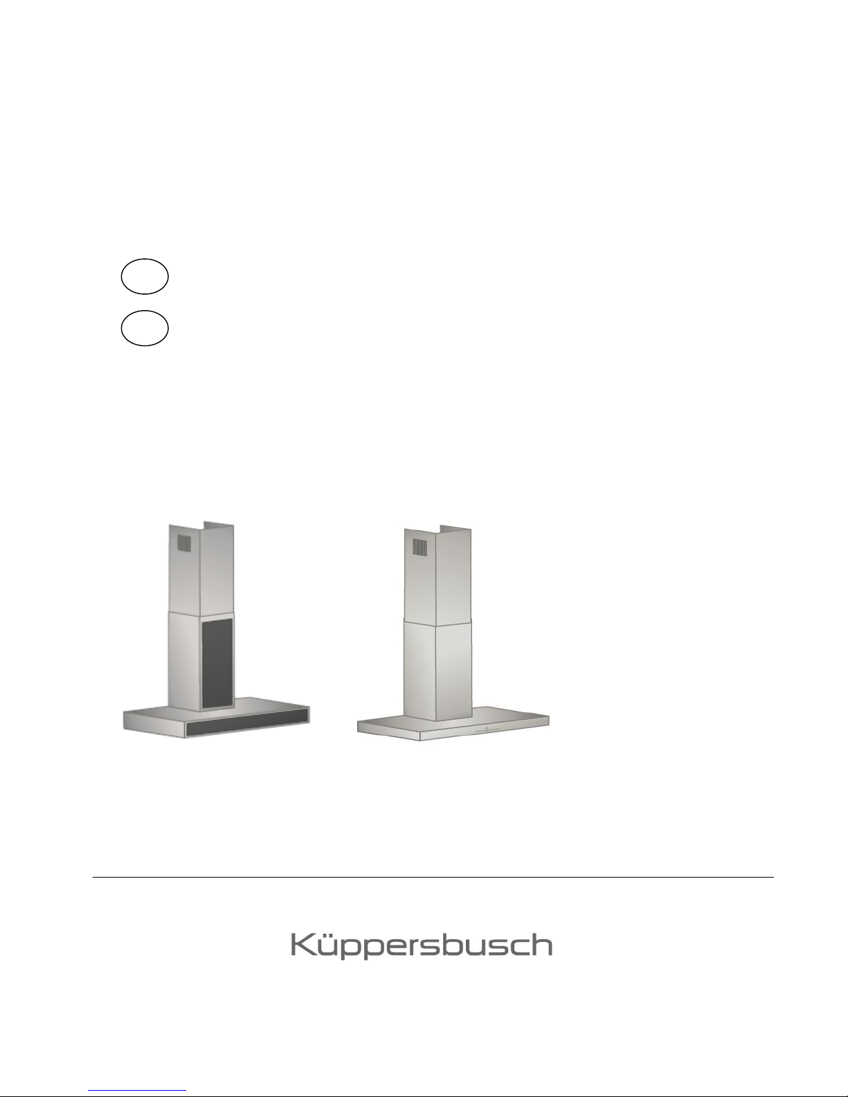
BEDIENUNGS- UND
MONTAGEANWEISUNG
IKD9885.0 IKD 12440.0 / IKD9440.0
KD9885.0 KD12440.0 / KD9440.0
GB INSTRUCTIONS FOR ASSEMBLY AND USE
GR


Contents
General
Contents 24
Your appliance data 25
Safety Instructions 26
Installation
Assembly instructions 28
Electrical connection 28
Other assembly instructions and tips 29
Mounting on a wall 30
Mounting on the ceiling 35
Operation
Switching your appliance on / off 38
Power controls 38
Automatic delayed stop 38
Switching the lamp on / off 38
Dimmer function 39
Filter saturation display 39
Remote control 40
Maintenance, Cleaning and Care
Housing 41
Grease filter 42
Charcoal filter 43
24

Please note:
We require the following details for your request for customer service so that our
customer service technicians can be well-prepared to carry out repairs and have the
required spare parts available:
1. Your exact address
2. Your telephone number and, if available, fax number
3. When can customer service call?
4. An exact appliance designation:
model no. and fabric no. (refer to the nameplate and/or the receipt)
Model designation: ...............................................................................................
E-number: ............................................................................................................
F/N: ......................................................................................................................
5. Date of purchase
6. An exact description of the problem or the kind of service you require
Please also have your receipt available.
This will help us to avoid wasting time as well as cutting down on expenses and we
will be able to work more efficiently for you.
25

Safety Instructions
This appliance complies with valid safety regulations. Improper handling may cause
damage to property and injury to persons.
Please read these instructions carefully before installing your appliance and using it.
It contains important information and tips on assembly, safety and maintenance.
Information concerning structural requirements
The following instructions must be observed when cooker hoods are used in the
extraction mode:
- In kitchens/rooms with no open fireplace, the air supply must ensure that no
negative pressure occurs in the room and that the hood can function properly.
- Important! Kitchens / rooms with an open fireplace, e.g. tile stoves, coal
ovens, fireplaces, etc., must always be provided with a sufficient supply of
fresh air. This is best ensured with a wall box for inlet air and exhaust air or
with a flip switch for the window.
Contact your local chimney sweep for information before making your plans.
He will have to give his approval for the hood and the inlet air and exhaust air
pipes before you put your hood into operation.
- Under no circumstances may the hood be connected to a smoke or exhaust
gas chimney that is used for other appliances (hot water tanks, boilers,
furnaces, etc.). Chimneys used for ventilating rooms or fireplaces may not be
used for the hood.
- Your local chimney sweep must give his approval if the hood is connected to
smoke or exhaust gas chimneys which are no longer in use.
- Valid national building regulations must be observed!
26

Safety instructions for assembly and use
- The metal grease filters must always be in place when the cooker hood is in
operation. Greasy vapours may otherwise be deposited in the hood and in the
extraction air system.
- In the case of gas cookers it is important to ensure that the cooking zones are
not operated without any cookware. Uncovered gas flames may damage
components of the cooker hood as a result of rising heat.
- Never flambé under the cooker hood as there is a risk of fire. The rising flame
could ignite the fat that has been deposited in the filter.
- Constant supervision is essential when deep-frying or cooking with oil or fat
under the hood because of the risk of fire.
- No other work may be carried out with an open flame. A fire may result and
damage the metal grease filter or other parts of the hood. This does not
include the proper use of a gas cooker.
Safety instructions for maintenance, cleaning and care
- Pull the mains plug out of the socket or switch off the relevant safety fuse in
the fuse box for the building when carrying out any maintenance or cleaning
work.
- The cooker hood may not be cleaned with a steam cleaner.
- Grease deposits may cause a fire if the instructions for maintenance and
cleaning are not followed.
27
INSTALLATION
Depending on the model, a minimum clearance of 60 cm must be maintained
between an electric hob and the bottom of the cooker hood when installing the hood.
A minimum clearance of 75 cm must be maintained for gas hobs (Fig. 1).
Fig. 1
electric hob min. 60 cm
gas hob min. 75 cm
Assembly instructions
Extraction or recirculation mode
When the hood operates in the extraction mode, the air that is extracted is cleaned
in the grease filter and lead outside through an exhaust air duct.
In the recirculation mode, the air that is extracted is cleaned in the grease filter and
also in a charcoal filter (extra). The clean air is then lead back into the kitchen.
Hoods supplied from the factory have been fitted for the extraction mode. You can
order the extra part required for the recirculation mode from us (also see the section
on “maintenance, cleaning and care”).
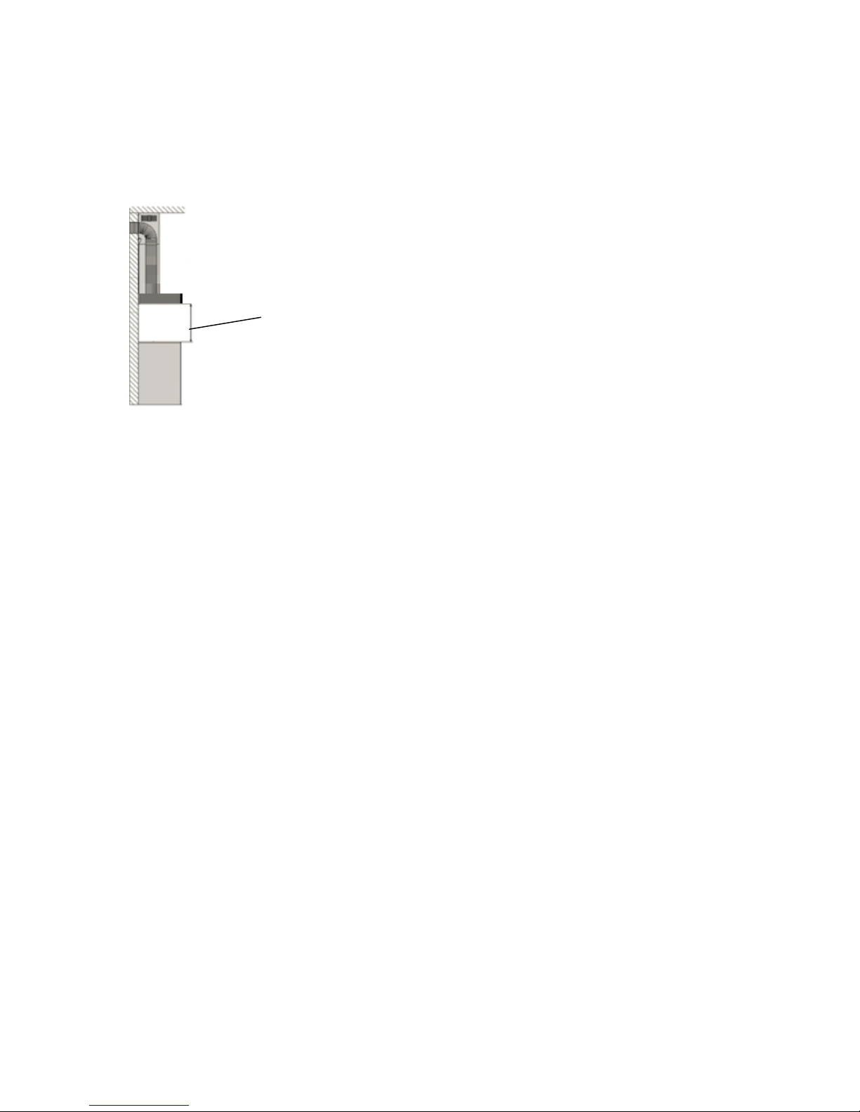
Electrical connection
Before connecting the hood to the mains, check that the voltage stated on the type
plate corresponds to the local power supply. The type plate is located inside the
hood. You will see it next to the motor once you have removed the grease filter.
The hood is supplied from the factory fitted with a mains cable and a plug. It can be
connected to any 230 volt, 50 Hz alternating current shockproof socket which has
been installed in accordance with regulations.
The socket should be located behind the chimney so that it is not visible. The socket
will not be accessible once the chimney has been mounted, so it must be possible to
cut off the electric circuit to which the hood is connected when maintenance work
needs to be carried out.
The hood complies with protection class 1 standards.
28

Other important information
In order to make sure that ventilation is optimal and that the hood operates quietly,
the extraction air system, including the wall box, must be at least 150 mm in
diameter.
Please observe the following when installing the exhaust air pipe:
- Use short, straight exhaust air ducts.
- Use as few pipe bends as possible.
- Use only smooth pipes.
- Exhaust air boxes and pipes with a diameter of 100 or 120 mm are not
suitable.
- Do not use a plastic flex exhaust air tube since this may make the operating
noise unpleasantly loud.
- When drilling holes for dowels make sure that lines running in the walls
(electricity, gas and water) are not damaged.
This cooker hood is intended for installation on a wall or a ceiling, depending on the
model. Please follow the drawings and instructions provided. We recommend that
you always wear the gloves that are supplied when mounting the hood in order to
avoid fingerprints on the stainless steel.
29

MOUNTING ON A WALL
KD9440.0E / KD12440.0E dimensioned drawing
KD9440.0E / KD12440.0E dimensioned drawing of installation dimensions
(back view)
30

KD9885.0GE dimensioned drawing
KD9885.0GE dimensioned drawing of installation dimensions (back view)
31

Take the wall mounting bracket shown in Fig. 2 and place it on the wall so that you
have the height you want when you mount the cooker hood. Make sure that you
maintain a minimum clearance of 60 cm between the hob and the bottom of the
cooker hood for electric hobs and a minimum clearance of 75 cm for gas hobs. See
Fig. 2.1 for the exact dimensions of the wall mounting bracket.
Fig. 2 Fig. 2.1
Now fasten the two mounting bars shown in Fig. 3 onto the holes that have been
provided on the top of the body / motor block of the cooker hood, on the right and left
next to the air exit of the fan motor and then hang the hood into the two clips on the
wall mounting bracket.
Fig. 3 Fig. 3.1
Fig. 4 shows the combination of the two steps for mounting the hood on the wall.
Fig. 4
32

You have several options for aligning the hood thanks to its multiaxial mounting
system.
To align the hood on the right and left hand side, you can either move the wall
mounting bracket to the left or right until it is in the ideal position by loosening the
screws and then fastening them again (if the hood needs to be moved by more than
0.5 cm) (Fig. 4.1). Or alternatively, if the hood only needs to be minimally moved, you
can hang the hood into the wall mounting bracket and then align and fasten it.
Fig. 4.1
To align the height of the hood when it has already been suspended, you will need to
unscrew and screw the two screws that go into the holes on the top clip of the
mounting bars evenly.
Fig. 4.2
If the cooker hood has not been horizontally mounted, the two screws will need to be
screwed in and out separately, until the hood is in the optimal / horizontal position.
If the cooker hood has not been mounted parallel to the wall, the clearance or
alignment of the hood to the wall can be adjusted or changed by loosening the two
fastening screws and pushing the mounting bars forwards and backwards (Fig. 4.3).
Fig. 4.3
33

To mount the chimney take the assembly clamp that has been provided (Fig. 5),
place it at the required height, generally right below the ceiling (Fig. 5) and then
fasten it. You will then need to make the connection for the extraction air and mount
the chimneys according to Fig. 5 and Fig. 5.1.
For the recirculation mode you will first of all need to follow the instructions given in
Fig. 5.2 before you mount the chimneys, also according to Fig. 5 and Fig. 5.1.
Please note:
Exctraction mode: Telescopic part of the chimney with recirculation air openings
facing down
Recirculation mode: Telescopic part of the chimney with recirculation air openings
facing up
Pull the telescopic chimney (B) upwards and fasten it to the assembly clamp (C) with
the screws (do not use a battery-operated screw driver!).
Fig. 5 Fig. 5.1 Fig. 5.2
34

MOUNTING ON A CEILING
IKD9440.0E / IKD12440.0E dimensioned drawing
IKD9855.0GE dimensioned drawing
35

Assembly diagramme
Ceiling
Ceiling
mounting bracket
Mounting ring
Mounting angle
Motor box
Stainless steel chimneys
Cooker hood body
36

Take the ceiling mounting bracket shown in Fig. 6 and place it on the ceiling so that
you have the height you want when you mount the cooker hood. Make sure that you
maintain a minimum clearance of 60 cm between the hob and the bottom of the
cooker hood for electric hobs and a minimum clearance of 75 cm for gas hobs.
Fig. 6
Now mount the four mounting angles in Fig. 7 onto the holes that have been provided
on the edges of the motor block (Fig. 7.1) of the cooker hood, then suspend these
mounting angles on the ceiling bracket and fasten them there with four screws.
Fig. 7 Fig. 7.1
Now take the telescopic chimney (Fig. 6.2) and pull it over the motor block that has
already been mounted. Fasten the body of the hood (Fig. 6.3) to the motor block.
Now fasten the shafts with the fastening clips.
Fig. 7.2 Fig. 7.3
The height of the cooker hood can be adjusted with the mounting angles. You can
use sheet metal hooks on the body of the hood to hang up the hood before you
finally mount it.
37
OPERATION
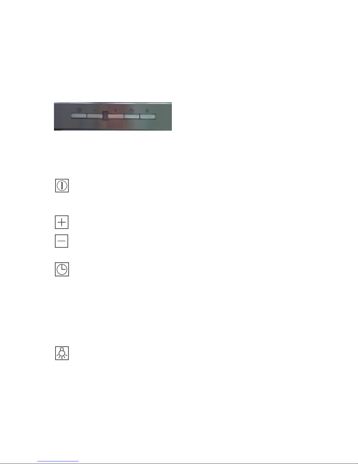
This cooker hood is regulated with touch-sensitive sensor controls or short-travel key
controls located on the front of the hood. The controls react when the corresponding
symbol is touched lightly or pressed.
Short-travel key controls:
You can regulate the power settings, the lamp, including the brightness level, as well
as the automatic delayed stop function with the sensor controls. A digital display
informs you about the setting that has been selected, the automatic delayed stop and
filter saturation.
Switching the cooker hood on / off
Touching this symbol will switch the cook hood on or off. When the hood is
switch on the fan will operate at power setting “2”.
Power controls
When the cooker hood is switched on, the power is controlled by pressing the
symbols “+” (to increase the power) and “-” (to reduce the power). Pressing the
symbol several times will increase or reduce the power setting from 1 – 4.
Automatic delayed stop
This cooker hood is equipped with an automatic delayed stop function which
automatically switches the hood motor off after 15 minutes. The automatic
delayed stop function should always be activated as soon as cooking has
been completed in order to remove the steam and odours that remain after
cooking. Touching the timer symbol lightly will switch on the automatic delayed
stop function. The power setting in the display will start flashing. The automatic
delayed stop function is switched off by touching the timer symbol or switching
off the cooker hood.
Switching the lamp on / off
The lamp is switched on and off by touching this symbol.
38

Dimmer function
The display will show two horizontal bars for approx. 5 seconds without a
break as soon as this symbol is touched (Fig. A). When the symbol is touched
again the display will show the level of brightness. The lamp is pre-set at
brightness level “9” in the factory. Touching the “+” and “-” keys will set the
brightness level of your choice. Press the “lamp” symbol once again to save
this setting.
Fig. A
Deleting the filter change display “C”
When the letter “C” is shown in the LED display, the charcoal filter will need to
be replaced (see also the section on “maintenance, cleaning and care”).
Hold the on/off key for approx. 5 seconds to reset the display. The function is
reset and the letter “C” will be deleted from the display.
39

IR remote control
An IR remote control (Fig. 8) may also be included with delivery, depending on
the model and its features. It can be used to operate and regulate all the
functions of the cooker hood from a distance of several metres. To do so, point
the remote control towards the cooker hood and press the function of your
choice on the remote control.
Fig. 8
Timer
Dimmer
Lamp
Switch on the automatic delayed
stop function
Set the dimmer function and
switch the lamp on and off
On/off switch
Increase/reduce power setting or
the dimmer setting
40
Maintenance, Cleaning and Care
It is absolutely essential to have your cooker hood regularly serviced in order to
ensure that it operates efficiently for a long time. When the metal grease filter is
clogged with particles of grease and dirt it will not work properly.
The charcoal filter (only used for the circulation mode) cannot be rinsed or
regenerated and must therefore be replaced at regular intervals. You can order
replacement charcoal filters from your specialist dealer or from our spare-parts
service.
Important! Pull the mains plug out of the socket or switch off the relevant safety fuse
in the fuse box for the building when carrying out any maintenance or cleaning work.
The cooker hood may not be cleaned with a steam cleaner.
Housing
Only clean the surfaces and control elements with a sponge cloth, detergent and
water as they are very sensitive to scratches and cuts.
When you have removed the metal grease filter, clean the accessible metal surfaces
in the interior of the cooker hood. When doing so make sure that you only use a little
liquid when working on the interior of the cooker hood or when cleaning it.
Do not use any acidic cleaning agents, agents containing solvents or abrasive agents
such as scouring powder or liquid scouring cleaner; use only detergents and cleaning
agents which are intended for stainless steel.
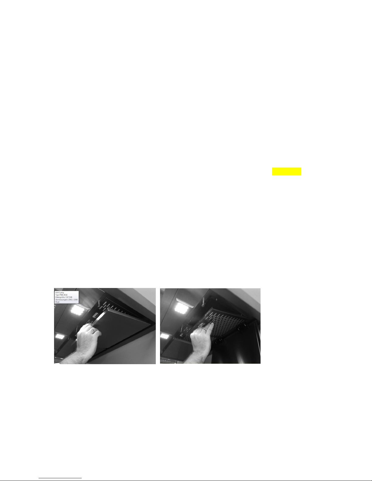
In the case of models KD9885.0GE and IKD9885.0GE you will need to fold down the
flaps of the edge suction system (Fig. 9 / Fig. 9.1) before you can remove the filters.
Fig. 9 Fig. 9.1
41

Grease filter
To remove the grease filter press the bar rail handle of the filter down and remove the
grease filter from the hood (Fig. 10). Then remove the grease filter from the stainless
steel frame (Fig. 10.2).
To replace the grease filter, first of all replace it in the stainless steel frame and then
return it to the hood. To do so, replace the bottom of the filter in the frame of the
hood, making sure that the two bottom clips are fitted exactly into the two holes of the
filter frame (Fig. 10.1). Press the bar rail handle down until the top part of the grease
filter has been properly inserted into the filter frame and then let the frame go.
Fig. 10 Fig. 10.1
Some of the models have a metal grease filter that is covered with a removable
stainless steel grid. The metal grease filter will have to removed before you put it into
the dishwasher. To remove the stainless steel grid, press the bar rail handle down
until the two movable clips have been pulled right down (Fig. 10.2) and then press
the metal filter out of the stainless steel grid (Fig. 10.3). Now put the metal grease
filter (Fig. 10.4) into the dishwasher and clean the stainless steel grid with a soft
cloth.
Fig. 10.2 Fig. 10.3 Fig. 10.4
42

Depending on how you cook and fry, the metal grease filters should be cleaned
approximately every two weeks.
Soak the metal grease filters and stainless steel frames well in hot soapy water,
clean them with a soft brush and then spray them thoroughly with hot water to rinse
them. Repeat the procedure if necessary.
The metal grease filters (not the stainless steel frames) may also be rinsed in the
dishwasher, using a standard 55 °C programme.
The metal grease filters should not be washed with dishes and glasses as grease
may be deposited on the dishes or scraps of food may collect on the metal grid.
Metal grease filters that are very clogged should be soaked well beforehand in hot
soapy water.
Please note! Make sure that the grid is not damaged when you clean the metal
grease filter. The metal surface may become discoloured as a result of frequent
cleaning or the use of aggressive detergents. This discolouration does not have any
effect on the functioning of the filter and gives no reason for complaint.
Replace the clean, dry metal grease filter in reverse order according to Fig. 10 ff.
Charcoal filter
To remove the charcoal filter (Fig. 11), pull the two front fastening clips in the filter
frame to the front. After you have removed the new charcoal filter from its packaging,
the filter should be shaken to distribute the granules evenly.
Make sure that the fastening clips on the filter point to the front when you insert the
new charcoal filter. First put the charcoal filter into the bottom of the frame and then
insert the front of the filter until it engages (Fig. 11.1).
Fig. 11 Fig. 11.1
43

The charcoal filter should be replaced after approximately three to six months.
The intervals for cleaning and replacement should generally be observed in order to
ensure that no greasy vapours are deposited on kitchen walls and units.
If the metal filter is not regularly cleaned when the hood is operated in the circulation
mode, the charcoal filter will also become clogged more quickly, impairing the
operation of the hood.
44
 Loading...