

Küppersbusch IKD 9600 Instruction Booklet
DE
GB
Bedienungsanleitung
F
Mode d’emploi
NL
Gebruiksaanwijzing
I
Libretto Istruzioni
Manual de Instrucciones
Bruksanvisning
Manual de Instruções
Instructions Booklet
IKD 9600
GR
E
P
S
14
○○○○○○○○○○○○○○○○○○○○○○○○○○○○○○○○○○○○○○○
○○○○○○○○○○○○○○○○○○○○○○○○○○○○○○○○○○○○○○○○○○○○○○○
GB
○○○○○○○○○○○○○○○○○○○○○○○○○○○○○○○○○○○○○○○○○○○○○○○
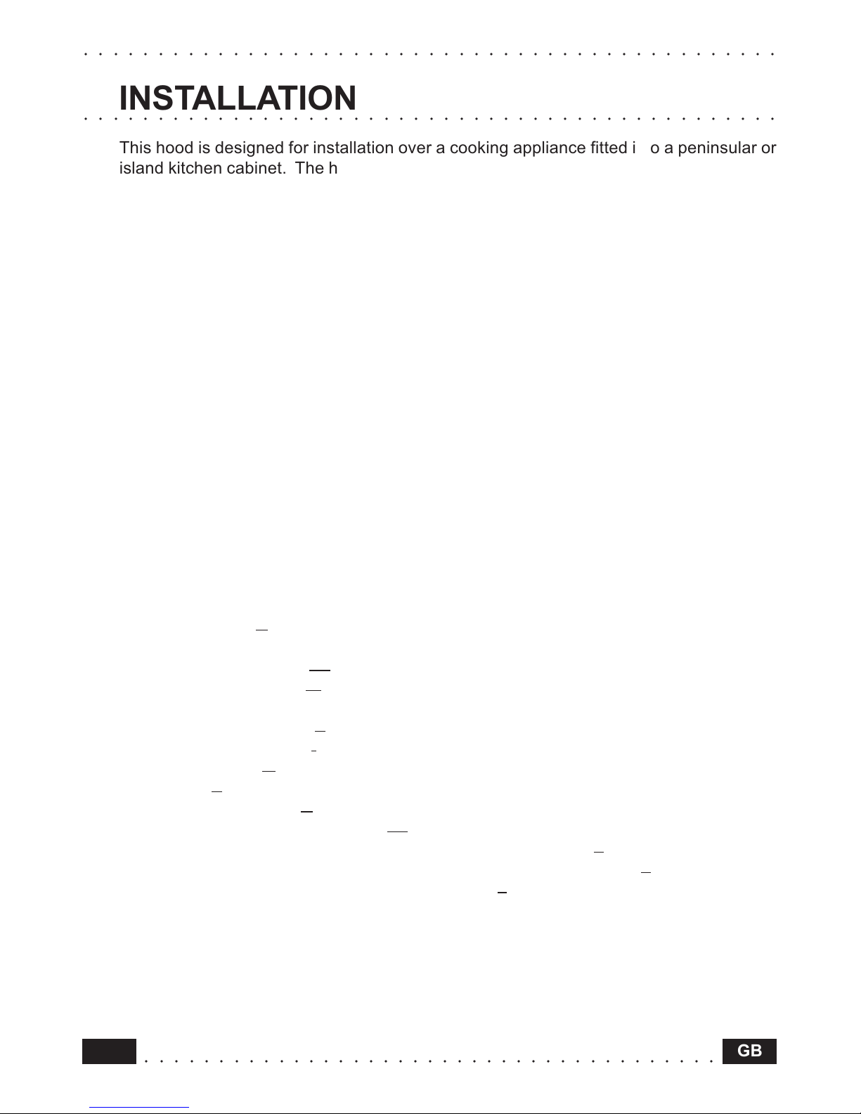
INSTALLATION
This hood is designed for installation over a cooking appliance fitted into a peninsular or
island kitchen cabinet. The hood can be fastened to the ceiling or to a wooden buttress,
using the substantial ceiling fixing system supplied, which is fully adjustable in height.
The hood can be used in either extraction mode (ducted to the outside) or in recirculation
mode (internal recycling).
Safety warnings
• Due to the difficulties which could be experienced when installing this hood, because
of the specific weight of the product, installation should only be carried out by a
qualified or competent technician, in compliance with all the rules concerning the
evacuation of contaminated air. The manufacturer declines all responsibility for any
damage or injury caused as a result of incorrect installation, poor workmanship or
failure to comply with the instructions provided in this manual.
• Do not connect the hood ducting to central heating flues, chimneys, etc..
• The minimum safety distance between the cooker top and the hood is 65 cm.
• Never do flambé cooking under the hood.
• Never leave frying pans unattended during use: overheated fats and oils may ignite.
• If the room in which the hood is to be used contains other non-electric appliances
(such as gas appliances), ensure that there is an adequate supply of air into the room.
When the hood is used in conjunction with other non-electric appliances the negative
pressure in the room must not exceed 0.04 mbar, to prevent fumes from being drawn
back into the room by the hood itself.
Components
The hood is made up of the following components (fig. 1):
• n. 1 hood canopy C, complete with controls, worktop illumination and fan unit
• n. 1 telescopic frame, comprising:
n. 1 upper frame section TS
n. 1 lower frame section TI
• n. 1 telescopic chimney stack, comprising:
n. 1 upper chimney stack S
n. 1 lower chimney stack I
• n. 2 venting grilles G
• n. 2 clamps F
• n. 1 recirculation spigot R
• n. 2 additional recirculation spigots P1
• n. 1 bag with screws for fixing the frame to the ceiling-buttress 1
• n. 1 bag with screws for fixing the chimney stack to the hood canopy 2
• n. 1 bag with screws for fixing the connection box 3
• n. 1 bag containing documents.
Instructions for installation
To facilitate installation, proceed in the order indicated below:
• Installing the Frame.
• Ducting or recirculation fitting.
• Connection to the mains power supply.
15GB
○○○○○○○○○○○○○○○○○○○○○○○○○○○○○○○○○○○○○○○
○○○○○○○○○○○○○○○○○○○○○○○○○○○○○○○○○○○○○○○○○○○○○○○
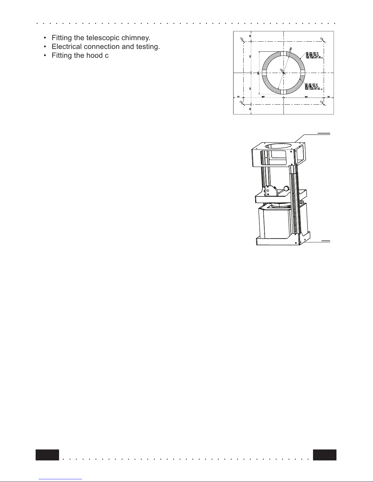
• Fitting the telescopic chimney.
• Electrical connection and testing.
• Fitting the hood canopy
Installing the Frame
The frame is suitable for fixing to the ceiling or to a
wooden buttress of suitable thickness, which must
be firmly anchored to the ceiling or to other bearing
structures.
• Using a plumb line or similar tool, identify and mark
the centre on the ceiling or buttress, starting from the
centre of the cooking appliance.
• Use the cardboard template provided to mark the
ceiling or wooden buttress, making sure that the
centres coincide and lining up one of the two axes (A
or B) of the template so that it is parallel with the long
side of the cooking appliance.
• Mark the position of the 4 fixing holes indicated on the
drilling template.
• Drill the holes as follows:
- Ceiling: 4 holes Ø 10 mm to fix the frame in position;
- Buttress: 4 holes Ø 8 mm to fix the frame in position.
Fixing to the Ceiling
Attention: Due to the many differing types of ceiling
construction, the choice of fixings is left to the
discretion of the installer. It is necessary to emphasise
that the fitting has to be absolutely accurate because
of the weight of the cooker hood and because of the flexing caused by accidental lateral
stresses on the appliance. Only the following types of ceiling are suitable for installing
the Island cooker hood:
• Solid concrete ceiling: use dowels for concrete, not supplied.
• Solid wooden buttress ceiling: use Ø 10 mm wood screws with a minimum length of 120
mm, not supplied.
• Cavity ceiling with inner space, having a wall thickness of about 20 mm; use, in this case
only, the 4 dowels and screws supplied in bag (1). Once fixed, make sure that the base
is absolutely stable, even when the metal frame is subjected to lateral stress. In all other
cases, if the ceiling is not strong enough in the area where the hood is to be fixed, the
installer must strengthen the area using suitable plates and counterplates anchored to
resistant structures.
Fixing to the Wooden Buttress
• Connect the base of the frame to the beam using the 4 screws size 5.2x70 with nuts and
washers, provided in bag (1)
TS
TI
4324665 01 - 001201
16
○○○○○○○○○○○○○○○○○○○○○○○○○○○○○○○○○○○○○○○
○○○○○○○○○○○○○○○○○○○○○○○○○○○○○○○○○○○○○○○○○○○○○○○
GB
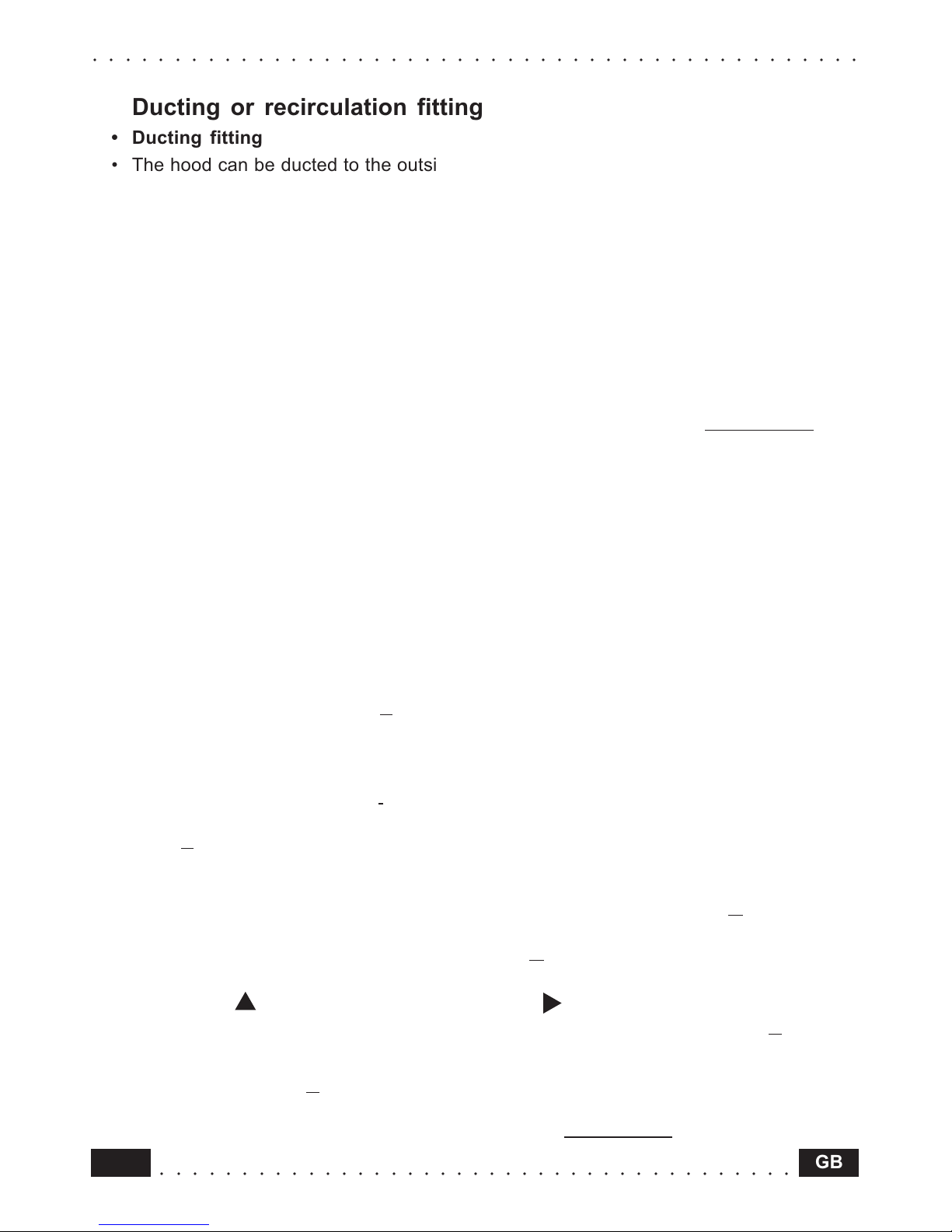
Ducting or recirculation fitting
• Ducting fitting
• The hood can be ducted to the outside using either rigid or flexible ducting Ø 150 mm,
the choice of which is left to the installer (fig.3).
• If the hood is supplied with the activated charcoal filters fitted, the filters should be removed
(see paragraph on Maintenance).
• Recirculation fitting
• The filtered air is returned to the room through the two plastic side grills G on the upper
chimney element S .
• Connect the pipe T to the round fan outlet, pushing it downwards, and fit spigot R in a
similar manner (make sure that the two additional side recirculation spigots P1 are fitted
to spigot R). Make sure that the height of the assembly R + T corresponds to the height
of the chimney outlet (fig.4).
• Fit the activated charcoal filters inside the canopy (see paragraph on
Maintenance ). Do
not fit the venting grilles until after the chimney has been installed.
Connection to the mains power supply
• Check that the mains voltage corresponds to the one indicated on the rating plate
inside the hood.
• Connect the hood to the mains, inserting a two-pole switch with contact aperture of
at least 3 mm.
• Ensure that the domestic electric system is properly earthed.
• The mains lead should be routed through the central keyhole in the frame before being
connected.
• Connect the mains lead to the power supply.
Fitting the telescopic chimney
• Fit the upper chimney stack S to the frame fastened to the ceiling or to the wooden
buttress.
• Fasten the upper chimney stack using two of the screws size 2.9x9.5 provided in bag (2),
making sure that you insert one screw on each side of the chimney.
• Fit the lower chimney stack I in a similar way, using two of the screws size 2.9x9.5
provided in bag (2), inserting the chimney stack into the same slot used for upper chimney
stack S.
• Warning: the top chimney is fitted with side outlets. If the hood is installed in the ducting
version, the chimney must be fitted with the outlets facing downwards, so that they are
not visible, and in this case it is not necessary to fit the directional grilles G. If the hood is
installed in the recirculation version, the chimney must be fitted with the outlets facing
upwards, and in this case the directional grilles G must be installed.
• Fit the two venting grilles, which snap onto the metal, into the housings provided, so that
the symbol
points upwards and the symbol points forwards. For recirculation
versions, also check that the venting grilles are properly inserted into clamp
R (fig. 5).
Fitting the hood canopy
• Fix the hood canopy C to the telescopic frame (fig.6) using 4 screws M6x10 provided in
bag (2).
• Remove the metal grease filters (see paragraph on Maintenance).
 Loading...