

BEDIENUNGSANWEISUNG
mit Montageanweisungen
Instructions for use and installation instructions
Instructions d’ utilisation et avis de montage
Gebruiksaanwijzing en montagehandleiding
Istruzioni di l’uso e di montaggio
Instrucciones de Uso e Instrucciones de Montaje
Instruções de uso com indicações para montagem
IKD 908.1/IKDEM 908.1
53 71 07 FC1
For your information
Please read the instructions in this booklet carefully as they contain important
information on the safety, installation, use and maintenance of your appliance.
Keep these instructions in a safe place.
Conditions of guarantee
The conditions of guarantee applicable for this product are subjeci to those
published by the representative in the relevant country.
Details regarding same may be obtained from the dealer from whom the
appliance was purchased. For claims under guarantee the sales receipt
must be produced.
General advice
Remember that the ventilation problem in the kitchen is often not solved merely by installing a cooker hood. For optimum effect and maximum ventilation efficiency the cooker hood requires a sufficient supply of air from the correct sources. Disappointing performance and the development of loud
noises are almost always the result of planning or operating errors.
Examples
–
Insufficient supply of fresh air
Result: The speed of the ventilation motor increases, the air capacity decreases and the noises become louder.
–
Saturated filter mats
Result: The air capacity of the cooker hood decreases and the fumes are
insufficiently cleaned.
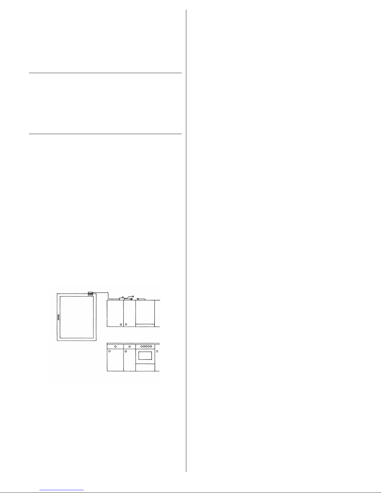
Example of how to use the cooker hood and the stove in complete safety:
A switch at the window prevents the cooker hood from being operated
when the window is closed.
Contents
Your appliance at a glance. . . . . . . . . . 14
Safety instructions . . . . . . . . . . . . . . . 15
For connections and functions
For operating your appliance
For operating the hood with stoves and heating appliances
with a naked flame
Before using your appliance for
the first time . . . . . . . . . . . . . . . . . . . 15
Cleaning the appliance for the first time
The control buttons
Inserting the battery
Resetting the working hour counter
Using the appliance . . . . . . . . . . . . . . 16
Switching on the lighting
Switching the motor on and off
Selecting the speed setting
Changing the standard setting
Switching on the automatic delayed stop
The cleaning interval for the fat filters
General instructions on use
Cleaning and maintenance . . . . . . . . . . 17
Cleaning the metal fat filter
Changing the battery of the remote control
Replacing a halogen lamp
What to do in case of trouble. . . . . . . . 18
Rating label
Installation. . . . . . . . . . . . . . . . . . . . . 18
Scope of delivery
Installation preconditions
Marking and drilling holes
Mounting the inner frame
Installing the exhaust pipe
Mounting the upper chimney panelling
Connecting the hood
Attaching the hood body to the chimney
Fastening the switch and control unit
Mounting the glass shelf
Mounting the bottom chimney panelling
Installing the fume trap
Mounting the filter mesh
Guideline for extraction paths. . . . . . . . 22
IKD 908.1 13

Your appliance at a glance
760–1160
∅ 878
∅ 898
∅ 400
650
115
250
14 IKD 908.1
Safety instructions
For connections and functions
Maintenance and repair work may only be carried out by an authorised
technician in accordance with the applicable safety regulations. Work
which has been performed improperly can endanger your safety.
Extraction appliances must not be connected to smoke or fume chimneys or to shafts used for ventilating rooms where stoves have been installed. Before extracting fumes into a smoke or fume chimney which is
not in use, please obtain approval from your local chimney sweep. When
extracting fumes, please observe the official regulations.
The minimum distance between the cooker hood and the cooker is
650 mm.
It must also be possible to access the mains plug after the appliance
has been installed. Otherwise, the household fuse must be switched off
before cleaning and maintenance work is carried out.
For operating your appliance
The fat filter must be cleaned and replaced regularly. There is a danger
of fire if the appliance is used with a saturated fat filter!
Only use the hood when the fat filters have been installed.
Never flambé dishes under the cooker hood!
Ignited rings of gas cookers and gas hobs must always be covered by
pots or pans.
Keep an eye on deep-fat fryers while in operation. Fat and oil which
ignites due to overheating can set fire to the cooker hood.
A glass shelf or the fume screen should not bear excessive or one-sided
loads. Do not hang anything on the railing! If the glass breaks, there
may be a danger of injury from falling pieces of glass!
Always keep children away from the cooker hood.
For operating the hood with stoves and
heating appliances with a naked flame
This relates, for example, to gas, oil or coal-fired heating appliances, continuous-flow heaters and hot water tanks: If the cooker hood is operated in extraction mode, such appliances may no longer have sufficient air required
for combustion and there is a danger of intoxication or explosion!
Operation is perfectly safe if the cooker hood and the stove are being used
simultaneously in rooms where a negative pressure of 0.04 mbar is not
exceeded. This ensures that the fumes from the stove are not sucked back
into the room.
This can be achieved if there are non-airtight openings in windows and
doors, ventilation wall boxes (supplying/extracting air) or other technical
devices, e. g. interlock devices so that a sufficient supply of combustion
air can flow back into the room.
When assessing the ventilation requirements, the ventilation system of
your entire home must always be taken into account. This means, for
example, the above regulations for operating cooking appliances (e.g.
hobs and gas cookers) are not applied. If in doubt, please consult your
local chimney sweep.
If the cooker hood is only used in recirculation mode - with activated
charcoal filters - there are no restrictions on operation.
Before using your appliance
for the first time
Cleaning the appliance for the first time
Glass surfaces
–
Wipe down with any of the usual glass cleaning agents.
Stainless steel surfaces
–
Clean with a damp cloth and a little washing-up liquid. Wipe dry afterwards.
The control panel
–
Wipe down with a soft, dry cloth free of fluff.
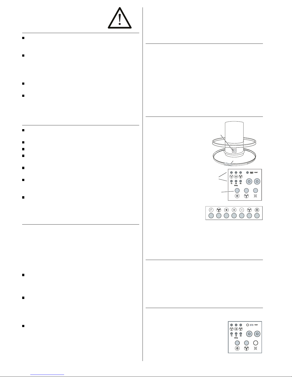
The control buttons
A control panel with three buttons
for the functions On/Off, lighting and
working hour counter is arranged on
the front of the hood chimney.
Control panel
All other functions are controlled
with the buttons on the remote
control unit.
To ensure that the remote control is always within reach, it can be mounted
on the bar of the bottom glass plate. The remote control has no control
lamps; active functions are indicated by the control lamps on the control
panel on the hood chimney.
Inserting the battery
You must insert and connect the 9V E-block provided so that you can use
the remote control.
–
Open the battery compartment of the remote control.
–
Insert and connect the battery. The connections for the poles are different and cannot be mixed up.
Resetting the working hour counter
The cooker hood has a working hour counter so that the fat filters can be
cleaned in good time.
–
Before or during initial use, press
the right-hand button on the
control panel to reset the working
hour counter to zero.
control panel
remote control
control lamps
buttons
IKD 908.1 15

Using the appliance
Be sure to observe the safety instructions on page 15!
The glass shelf may be loaded up to max. 6 kg.
Switching on the lighting
–
Switch the halogen lamps on or
off using the control panel or the
remote control.
Switching the motor on and off
–
Press the On/Off button on the
control panel or on the remote
control to switch the hood on and
off. When the motor is running,
the control lamp on the control
panel comes on.
When the motor is switched on, the standard setting of medium speed is
selected; it combines good extraction with a low noise level. After initial
use, the speed setting last used is selected when the motor is switched on.
Note: The standard setting can also be activated by pressing a button. You
can change the standard setting at any time if you think a different speed
setting is more appropriate (see Section “Changing the standard setting”).
Selecting the speed setting
–
Select a speed setting on the
remote control with the plus or
minus buttons: The minus button
reduces the motor speed, the plus
button increases it.
Important: If you press the button for the standard setting within 10 seconds from pressing the plus or minus buttons, the standard setting is deleted and replaced by the current settings.
–
To set the highest speed setting
immediately (high-speed setting),
press the raised button on the
right.
The high-speed setting provides about 20% more power than the highest
speed that you can set with the plus button.
A control lamp on the control panel
indicates that the high-speed setting
has been selected; at the same
time, the control lamp with the
marking 15 also comes on: The
high-speed setting is automatically
switched off after 15 minutes and
the appliance continues to run at the
standard setting.
–
In order to change back to the
standard setting before expiry of
the 15 minutes or from another
speed setting, press the button
illustrated on the right on the
remote control. The control lamp
on the control panel comes on.
Changing the standard setting
If you want, you can replace the standard setting at any time with the
setting you prefer.
–
Switch the appliance on and
select the speed setting which
you would like to store as the
standard setting.
–
Then press the standard setting
button within 10 seconds until
the control lamp on the control
panel flashes. The new standard
setting has now been stored.
Switching on the automatic delayed stop
You can let the hood continue to run after cooking at the preset operating
speed for 15, 30 or 60 minutes in order to remove any remaining fumes.
The motor and lighting are automatically switched off after the preset time.
–
Press the button with the clock
once so that the hood coasts at
the current operating speed for
15 minutes. The corresponding
control lamp flashes on the control panel.
16 IKD 908.1

–
If you press the clock button twice, you prolong the delayed stop time to
30 minutes; pressing it three times gives you a delayed stop time of one
hour.
–
In order to change the preset delayed stop time, press the clock button
repeatedly until the control lamp for the desired delayed stop flashes. The
delayed stop time now starts again at zero.
–
During the delayed stop time you
can naturally also switch off the
hood when you want.
The cleaning interval for the fat filters
After about 100 hours of operation
the right-hand control lamp on the
control panel flashes to remind you
that the fat filters have to be cleaned.
–
Press the right-hand button on the control panel to switch off the control
lamp. This resets the working hour counter to 0.
–
Then switch off the power circuit for the hood (de-activate fuse) and
clean the fat filters (see Section “Cleaning the metal fat filters”).
General instructions on use
in extraction mode in recirculation
mode
Appliance Switch on
appliance
on starting cooking on starting cooking
Switch off
appliance
ca. 5 min. after
finishing cooking
ca. 15 min. after
finishing cooking
Position of Door open closed
Window closed open
The room
air is cleaned of
Moisture X —
Heat X —
Fat X X
Odours X X
Cleaning and maintenance
Danger! Before all cleaning and maintenance work disconnect the
appliance from the power supply by pulling out the mains plug or
by switching off the household fuse!
Caution! Do not use any abrasive or sharp cleaning agents!
–
Clean the hood on the inside and outside with a damp cloth and a mild
liquid detergent.
Control panel
–
Carefully wipe the control panel now and again with a soft cloth which is
free of fluff.
Glass surfaces
–
Clean the fume trap and the glass shelf with a damp cloth and a little
hand detergent or one of the usual glass cleaning agents.
Stainless steel parts
–
Clean stainless steel parts with a damp cloth and a little washing-up
liquid. Then wipe dry. Use one of the usual stainless steel cleaning
agents from time to time.
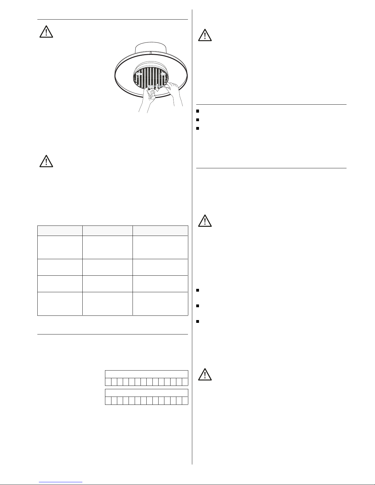
Cleaning the metal fat filter
The metal fat filter must be cleaned when the right-hand control lamp on
the control panel flashes.
–
Undo the screws holding the metal
mesh under the hood.
–
Remove the mesh and the fat
filter.
–
Clean both of them in a dishwasher or by hand with a mild
liquid detergent. Rinse and dry
well before installation.
–
Insert the filter and the mesh
again and screw tight.
–
If, after the filter has been cleaned, the right-hand control lamp on the
control panel still flashes when the hood is switched on, press the righthand button to reset the hour counter to zero and switch off the lamp.
Changing the battery of the remote control
When the hood no longer reacts to the buttons on the remote control, you
probably have to change the battery in the remote control.
–
Remove the cover of the remote control.
–
Undo the battery connections.
–
Remove the battery, insert a new one (9V E-block) and connect it.
–
Close the cover again.
IKD 908.1 17
Replacing a halogen lamp
Caution! Only replace defective halogen lamps with lamps of the
same type.
–
Undo the screws of the spotlight
holder.
–
Carefully pull the halogen spotlight
downwards out of the socket.
–
Insert a new spotlight (20 Watt)
into the socket with slight
pressure.
–
Screw the holder tight again.
What to do in case of trouble
Repairs should only be carried out by an authorised technician.
Before carrying out any repair work, the appliance must bedisconnected from the power supply by pulling out the mains plug or
switching off the household fuse.
First check whether there has been any case of maloperation. You can deal
with some problems that occur yourself.
Problem Cause Remedy
The cooker hood
cannot be switched
off.
Defective electronic
component.
Disconnect the mains plug
an call Customer Service.
Halogen lighting not
working.
Defective lamp. Replace lamp.
Light-emitting diode
not working.
Defective light-emitting
diode.
Call Customer Service.
Power of the cooker
hood becoming
weaker.
Filter has not been
changed in proper time.
Change filter.
Rating label
The rating label will become visible when you have removed the fat filter or
the activated charcoal filter. In case you have to consult Customer Service,
please make a note of the following data on the rating label before or while
installing the cooker hood:
Serial number:
Model designation:
Installation
Danger! The cooker hood may only be installed and connected by
an authorised technician.
Observe the safety notes on page 15!
Caution! Do not carry the hood by holding the railing of a glass
plate.
The fitter requires at least one helper for some operations.
Scope of delivery
Inner frame, chimney panelling, drilling template, attachment material
Hood with motor, hood glass, remote control
Glass shelf
IKDEM 908.1: With the hood version with an external motor, the motor is
supplied separately.
Installation preconditions
Please also observe the notes on fume extraction on page 22.
The island canopy hood IKD 908.1/IKDEM 908.1 can only be connected as
an extractor; recirculation mode is not possible.
Ceilings suitable for fastening
Caution! The ceiling structure must be suitable for the total weight
of the island canopy hood.
The hood is attached to the room ceiling in such a way that there is a
distance of at least 650 mm between the cooking surface and the hood
lower edge.
The fitter is always responsible for selecting the correct fastening material.
The fastening method must be suitable for the weight of the island canopy
hood and the lever forces which occur when side pressure is applied to the
appliance when installed.
The enclosed dowels and screws are suitable for ceilings made of
perforated bricks or concrete bricks which are 20 mm thick.
For solid concrete ceilings you must use special concrete dowels from a
specialist store.
For solid wooden ceilings you must use wood screws of sufficient thickness and length.
Electric connection
The hood is fitted with a normal mains plug and there should therefore be a
socket outlet (230V AC) near the point of installation.
Danger! The hood must be disconnected from the mains for all installation and maintenance work. If the mains plug can no longer
be reached after installation, you must switch off the relevant
household fuse.
18 IKD 908.1

Extraction path upwards
At the installation point of the hood there must be an exhaust channel
150 mm in diameter in the room ceiling.
Extraction path to the side
The hood must be connected by an additional exhaust channel to the
exhaust opening (150 mm diameter) in a room wall.
Exhaust with external motor (IKDEM 908.1)
The exhaust air can be extracted upwards or to the side (see above). The
control cable of the external motor should come out of the ceiling at the
installation point of the hood with a free cable length of about 1000 mm.
Marking and drilling holes
Note the following for marking the holes:
The power cable and, where applicable, the control cable of the external
motor are passed through the recesses at the exhaust opening of the
cover into the interior of the chimney.
Install the hood so that the cables are hidden by the chimney panelling.
The hood should hang centrally over the cooking surface so that as
many fumes as possible are extracted directly.
–
Align the drilling template above the cooking surface and mark the holes.
–
Drill holes for the enclosed dowels and insert dowels.
Mounting the inner frame
The length of the inner frame governs the length of the telescopic chimney.
Caution! When the hood is installed, the distance between the
lower edge of the hood and the cooker must be at least 650 mm.
The distance between the lower edge of the inner frame and the
cooker must accordingly be 952 mm.
–
Pass the customer’s power cable and, where applicable, the control cable
of the external motor through the ceiling plate of the inner frame.
–
Screw the inner frame to the
ceiling.
–
Set the length of the inner frame
so that the distance between the
cooking surface and the lower
edge of the inner frame is at least
952 mm.
–
Screw the two parts tight together
again.
Installing the exhaust pipe
–
Cut the exhaust pipe supplied to
the appropriate length and attach
with a clip to the customer’s
exhaust pipe.
–
Let the customer’s power cable
and, where applicable, the control
cable of the external motor hang
down outside the exhaust pipe.
Mounting the upper chimney panelling
–
Push the upper chimney panelling
over the inner frame and screw
on with two screws.
952 mm
IKD 908.1 19

Connecting the hood
Before you fasten the hood to the chimney, you must remove the filter
mesh under the hood and connect the power cable. If you are using an
external motor, you must also connect the control cable of this motor.
–
Undo the screws with which the
mesh is fastened under the hood.
Remove the mesh with the fat
filter.
–
Place the hood body under the
chimney ready for connection.
Turn the hood body so that the
opening for the control element is
facing the desired direction.
–
Join the power cable of the hood
to the customer’s power cable.
Attaching the hood body to the chimney
–
Screw the four screws on the
upper side of the hood body in far
enough to hold the hood body.
When mounting the hood body, make sure that the opening for the control
unit is facing the desired direction.
–
Raise the hood and guide the four
screws through the lug-shaped
holes.
–
Turn the hood body until the
screws are hanging in the narrow
end of the screw holes.
–
Tighten the screws.
–
Fasten the exhaust pipe over the
blower opening with the enclosed
pipe clip.
–
Hood with external motor:
Remove the cover of the switch
and control unit and connect the
control cable of the external motor
to the terminal strip illustrated.
Fastening the switch and control unit
–
Re-assemble the switch and
control unit and fasten with two
screws in the hood body.
Mounting the glass shelf
–
Place the glass shelf from above
onto the edge of the bottom
chimney panelling.
–
Fasten the glass shelf to the
bottom chimney panelling with the
four chromium-plated screws.
20 IKD 908.1

Mounting the bottom chimney panelling
–
Push the bottom chimney
panelling together with the glass
shelf from below over the hood
body. The writing for the control
panel must be located above the
opening for the control element in
the hood body.
–
Fasten the chimney panelling to
the hood body with two screws.
–
Insert the control element from
below through the opening in the
hood body into the bottom
chimney panelling.
–
The control element is held with
clips. Carefully push the element
into the holder until an audible
click confirms that it is sitting tight.
Installing the fume trap
–
Raise the fume trap and connect
the three cables for the lighting.
–
Then hold the fume trap under
the hood body so that the two
screw holes marked with a red
dot lie above one another.
–
Fasten the fume trap with three
screws.
Mounting the filter mesh
–
Screw the filter and filter mesh
under the hood again.
IKD 908.1 21

Guideline for extraction paths
Use round pipes with a 150 mm diameter or rectangular extraction channels
with a cross section of 90 x 220 mm.
You should use the following schematic diagrams as a guide for the extraction paths:
Extraction path through the walls
Here a telescope wall chock which can be adjusted to different wall thicknesses is built into the wall. The exhaust pipe should bend outwards slightly
so that the condensation water can flow away easily.
Extraction through the kitchen ceiling and roof
The height of the exhaust pipe must not exceed 2.5 m. The pipe must be
heat insulated or an air-trap seal must be installed.
Extraction into an existing exhaust shaft
The exhaust air must only be introduced into an existing exhaust shaft if
this is insulated against damp and is not already used for fuel purposes.
Have the chimney sweep responsible approve the use of the shaft.
Please note:
If the extraction channel is led through cold rooms, condensation may
form.
If the extraction channel has several bends, is very long or has a very
small diameter, the suction power can be considerably reduced. The motor may become loud and irregular.
The crucial factor is the correct transition of the exhaust channel into
the chimney.
View from the side
View from above
Incorrect!
Best way
Correct
22 IKD 908.1
 Loading...