

Page 1
224440 M91 1
GEBRAUCHS- UND
MONTAGEANWEISUNG
INSTRUCTIONS FOR FITTING AND USE
INSTRUCTIONS DE MONTAGE ET D’UTILISATION
GEBRUIKS- EN MONTAGE-INSTRUCTIES
ISTRUZIONI PER L’USO ED IL MONTAGGIO
INSTRUCCIONES PARA EL USO Y MONTAJE
MANUAL DE INSTRUÇÕES DE USO E DE MONTAGEM
œƒ«√…≈” ◊–«”«” ¡… ”’Õ¡–ÃœÀœ√«”«”
INSTRUKCJA OBSŁUGI I MONTAŻU
HASZNÁLATI ÉS BESZERELÉSI UTASÍTÁS
Einbau-Glaskeramik-Induktionskochfeld mit Touch-Control-Bedienung
Built-in glass ceramic induction hob with Touch-Control operation
Plaque de cuisson vitrocéramique à induction à encastrer
avec commande Touch-Control
Keramische inbouw-inductiekookplaat met tiptoetsbediening
Piano di cottura ad induzione da incasso in vetroceramica
con comandi Touch Control
Encimera de vitrocerámica por inducción incorporada
con mando Touch Control
Placa de cozinhar de indução em vitrocerâmica, com comando Touch-Control
Εντοιχιζόμενο υαλοκεραμικό επαγωγικό πεδίο μαγειρικής
με χειρισμό Touch-Control
Indukcyjna szkło-ceramiczna płyta grzewcza
z systemem sterowania Touch-Control
Beépíthető kerámiaüveg indukciós főzőlap touch-control vezérléssel
Page 2

12 224440
You now own a glass ceramic hob with Touch-Control switches.
Chapters 2 and 3 of these Operating Instructions contain information on how you can make sure that your hob
gives many years of service.
These Operating Instructions are for use with several types of hobs. The rating label on the front of these
Instructions will show you which type you have bought.
Contents
1. Operations
1.1 Your new hob
1.2 Touch-Control operating panel
1.3 Touch-Control operations
2. Things to watch out for
2.1 Important tips for induction
2.1.1 Induction cooking zones and cooking ware
2.1.2 Protection against overheating
2.1.3 General
2.2 Important
3. Cleaning and maintenance
4. Fitting by trained personnel
4.1 Worktop cut-out
4.2 Installation
4.3 Electrical connection
4.4 Maintenance and repair work
Safety instructions
Caution!
People who are not familiar with the built-in hob must only be allowed to operate it under
supervision.
Generally keep little children away from the appliance and never allow them to play with the
appliance.
Instructions on environmental protection
Disposing of the packaging
Please dispose of the packaging that came with your appliance in an environmentally friendly way.
Recycling in this way saves on resources and cuts down on waste.
Disposing of old appliances
The symbol on the product or on its packaging indicates that this product may not be treated as household
waste. Instead it shall be handed over to the applicable collection point for the recycling of electrical and electronic
equipment. By ensuring this product is disposed of correctly, you will help prevent potential negative
consequences for the environment and human health, which could otherwise be caused by inappropriate waste
handling of this product. For more detailed information about recycling of this product, please contact your local
city office, your household waste disposal service or the shop where you purchased the product.
Page 3
224440 13
1. Operations
1.1 Your new hob
This manual covers the models: .GKST 58 .., .GKST 75 .., FGKST 58 .., FGKST 75 ..
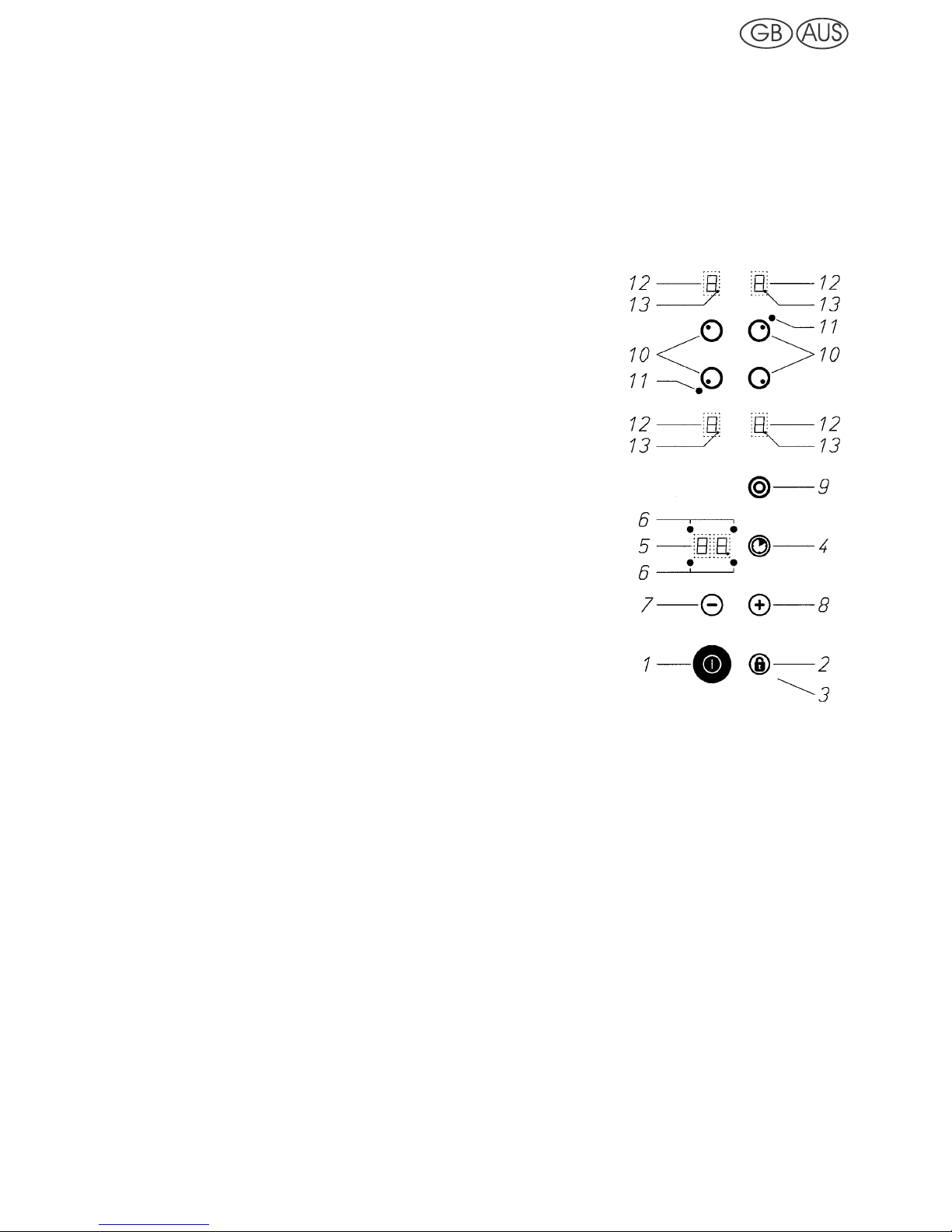
1.2 Touch-Control operating panel
After the supply voltage has been connected (mains connection), a self-test is carried out which is concluded when
a short acoustic signal is to be heard.
N On/off switch (control)
O Locking key
P Control lamp lock (control)
Q Timer key
R Time display
S Timer control lamp
T Minus key
U Plus key
V Dual-circuit key
M Cooking zone key
> Control lamp for switching on the dual circuit
? Cooking level display
¬ Cooking zone stand-by dot
(lit: cooking zone can be used)
1.3 Touch-Control operations
Each key operation is always confirmed by an acoustic signal.
Pressing the on/off switch key
N switches on the control system. A “0” is lit for the cooking level indicators ? and
the cooking zone stand-by dot
¬ blinks. The next action must be carried out within 10 seconds, otherwise the
control system will automatically switch off again.
To switch on a cooking zone, press the corresponding cooking zone key
M of the required cooking zone. The
appropriate cooking zone stand-by dot
¬ of the activated cooking zone lights up.
Select a cooking level from 1 to 9 by means of the minus or plus keys
T/U. When switched on, each cooking zone
can be switched off again at any time. To do this, the required cooking zone must be activated. The cooking zone
stand-by dot
¬ lights up.
The minus key
T can be used to turn the cooking level down to “0”; if the minus and plus keys T+U are pressed
at the same time, the cooking level can be switched off directly.
In all cases the complete control system can be switched off at any time by pressing the on/off key
N.
Pressing locking key
O prevents all the keys - with the exception of the on/off key - from being operated by
mistake. This state is indicated by control lamp
P. Pressing the locking key O cancels this command again.
Page 4
14 224440
Residual heat display
The residual heat display is by means of an illuminated “H” on the appropriate cooking level display ?.
Parboiling boost (if existing)
Switch on the cooking zone by means of corresponding cooking
zone button
M. Press the minus key T and select cooking level
9. Then switch on the parboiling boost by means of the plus key
U. During the parboiling stage, the cooking level display ?
switches continuously between the “A” sign (parboiling boost)
and the cooking level which has been set. Now you can select
the subsequent cooking level 1 – 8. If you quit cooking level 9
without selecting a subsequent cooking level from 1 – 8, then
the parboiling boost is shut off automatically after 10 seconds.
The parboiling boost time depends on the subsequent cooking
level which has been selected; details are given in the enclosed
time table.
If the plus key
U is selected after the required subsequent
cooking level has been selected, the parboiling boost time is
adjusted upwards in accordance with the time chart. If the
minus key
T is pressed after the required subsequent cooking
level has been deselected, the parboiling boost is stopped
beforehand.
Switching on the second element (if existing)
The two-circuit connection of the respective cooking zone can only be effected after the corresponding cooking
zone has been activated and switched on. Switch on the second heating element by means of the second element
key
V. The control lamp > lights up. The outer element is switched on. To switch off, the two-circuit cooking zone
must be activated and the two-circuit key
V operated. The control lamp > goes out, the outer element is switched
off.
Pan recognition
An advantage of the induction heating method is the pan recognition. If there is no pan or a too small pan placed
on the hotplates, no energy ist transmitted. If the cooking zone is switched on, the pan symbol “u” flashes in the
cooking level display
?. During the next 10 minutes the pan recognition will identify a pan that has been placed
and it will switch on the selected level. In the same way, the power supply to the cooking zone is interrupted, if the
pan is removed from the cooking zone. If the pots and pans placed on the cooking zone are of smaller dimension,
and the pan recognition still switches on, then the power supply will take place with less power.
Power boost
For the induction cooking zone marked by a "P" an additional power boost can be activated for a fast parboiling
boost. To switch on and off the twin circuit/power key
V must be activated. To do this, the induction cooking zone
must be activated and switched on. If no twin circuit key exists, the power boost must be activated as desirable in
the section “parboiling boost”. By activating this power mode, the power supply for the cooking zone will be
increased for the time of max. 10 minutes. This will be indicated by a “P” in the cooking level display. The power
supply for the corresponding induction cooking zone is decreased for this time. This will be indicated by continuous
changing in the display between selected cooking range and decreased cooking range. After switching back from
the power mode, the corresponding cooking zone provides the full power.
Tabl
e of times
PB = Parboiling boost,
in minutes:seconds
Cooking level PB (min:s)
1 01:00
2 03:00
3 04:48
4 06:30
5 08:30
6 02:30
7 03:30
8 04:30
9—
Page 5

224440 15
Timer
The timer can be used to automatically switch off a cooking zone after a pre-set time of between 1 and 99 minutes.
The required cooking zone must be activated, stand-by dot
¬ lights up. Select a cooking level from 1 to 9 by
means of the minus or plus keys
T/U. Then press timer key Q. The timer display R shows “00”. Select the
required cooking time between 1 and 99 minutes by means of the minus or plus keys
T/U. The control lamp S of
the selected cooking zone lights up.
The selected cooking time can be altered at any time. Activate the relevant cooking zone, press timer key
Q and
change the cooking time by means of the Minus or Plus keys
T/U.
When the pre-set cooking time has finished, the cooking zone switches off automatically and an acoustic signal
sounds for two minutes. This can be switched off by pressing any key.
If you want to switch the timer off beforehand, press cooking zone key
M and timer key Q. The minus key T can
now be used to set the timer
R to “00”, or alternatively this can be done by simultaneously pressing the minus and
the plus keys
T+U.
The timer can also be used as an egg timer when none of the cooking zones are activated. In this case, no cooking
zone should be activated when the timer
Q is being set (the cooking zone stand-by dot ¬ does not light up).
Safety switch-off
The maximum operating time for each individual cooking zone
is limited, and details are shown in the enclosed table of times.
When the safety switch-off has switched off the touch control
system, a “0” or an “H” is shown in the cooking level display
?
if there is still any residual heat left. Pressing the on/off switch
key makes the control system ready for operation again.
If more than one key is pressed simultaneously - with the
exception of the minus and plus keys - the control system will
not accept this as a valid command. If one or more keys are
activated for longer than 30 seconds, for example by boiling
over or the weight of a pan, the control system assumes that
there is an error and switches off automatically. If key operation
continues, a constant acoustic signal sounds.
2. Things to watch out for
2.1 Important tips for induction
2.1.1 Induction cooking zones and cooking ware
Your hob is equipped with induction cooking zones which are characterised by high performance when it comes
to quick heating and energy saving. The heat is generated directly in the bottoms of the pots where it's needed,
without a loss of energy through the ceramic hob. That's why the energy consumption is lower than with normal
radiation heating elements.
The ceramic hob is not directly heated, though it becomes hot due to the effect of heat reflected by the pan. When
the cooking zones are switched off, a hot cooking zone is indicated by the flashing “H” (residual heat indicator). In
induction cooking zones, heating is achieved by means of an induction coil installed below the ceramic hob which
produces an electromagnetic field. With the use of magnetizable pans or dishes made of steel, steel mesh or iron
cast (suitable for induction ceramic hob), energy is transmitted directly to the bottom of the equipment.
Only use induction cooking zones with suitable cooking utensils, made of materials such as steel, steel
mesh or cast iron. Stainless steel pans with copper or aluminium bottoms and glass pans are not suitable.
When you purchase a set of pans, check for the label “Suitable for induction”.
When cooking on an induction hob, only use pots and pans with a flat, smooth base. Cooking and baking
with warped cookware, parts of which may not even make contact with the cooking zone, can cause
damage to the cookware and to the glass ceramic hob as a result of overheating.
Table of times
MOT = maximum operating time,
in hours
Cooking level MOT (h)
16
26
35
45
54
61,5
71,5
81,5
91,5
Page 6

16 224440
2.1.2 Protection against overheating
The ceramic hob is provided with a protection against overheating, which protects the electronics against damage.
The protection against overheating works in several stages. If there is a significant increase in the heat of the
ceramic hob, then a two-stage fan switches on. If this is not enough, then the power level mode will be deactivated
and the power for the individual cooking zones decreased or switched off completely. Full power will be available
again once the ceramic hob has cooled down.
2.1.3 General
The best transmission is obtained when the pans and the cooking zone are of equal dimension.
For the minimum or maximum pan bottom diameter for the cooking zone, please see the following table.
Always use a lid. Energy is wasted if you cook without a lid placed correctly on the pan. Always take away overflow
food.
Clean the hob before using it for the first time.
2.2 Important
Attention: The surfaces of the heating and cooking zones become hot during use. Keep small
children away at all times.
Always ensure that no hard objects are dropped onto the cooking surface. Under certain circumstances the
material is sensitive to mechanical stresses and strains. A heavy knock or blow in a small area can cause the
ceramic hob to break. If careless treatment results in a break, split or crack, the ceramic hob must immediately be
taken out of use and disconnected from the mains power supply. To do this, switch off the safety switch for the
oven connection in the fuse box. Customer Service must be contacted.
Objects made out of metal, like knifes, forks, spoons and lids should not be placed on the cooking zones,
because they might become hot.
The cooking zone must be switched off after use by means of the touch control and not only via pan
recognition. This is to avoid accidental activation.
Do not use the glass ceramic hob as a storage area! Never prepare food in aluminium foil and plastic containers
on the hot cooking area.
Do not switch the hob on without using it for cooking. Do not place combustible, volatile or heat deformable objects
directly underneath the hob.
When preparing food with fat or oil stay nearby. Overheated oil can ignite. Never pour water into burning fat or oil.
Risk of burning! Cover the dish in order to extinguish the fire and switch off the cooking zone. Let the dish cool
down on the cooking zone.
In addition, make sure that leads from electrical appliances plugged into nearby sockets cannot come into contact
with the hotplates.
Never clean the glass ceramic hob with a steam cleaner or similar appliance!
Care must be taken when using double boilers (bain maries), for the simmering water may
dry up unnoticed, resulting in damage to the pot and to the hob, in the event of which no
liability will be assumed.
Cooking zones Pan bottom diameter
Diameter min. max.
210 mm 180 mm 220 mm
180 mm 150 mm 190 mm
145 mm 120 mm 160 mm
Page 7

224440 17
3. Cleaning and maintenance
Always clean the hob after it has cooled down. Even the slightest amount of dirt
will burn into the surface the next time you switch it on. Use only recommended
cleaners. Steel wool, cleaning sponges and abrasive powders scratch the
surface. Do not use oven sprays as these are aggressive and damage the
surface.
Light amounts of dirt
Use a damp cloth or a warm rinse to clean light amounts of dirt from the surface.
Rinse with cold water and then dry thoroughly. Use vinegar, lemon juice or a
calcium dissolving agent to remove water stains from the surface. If these agents
come into contact with the frame, wipe them off with a wet cloth, otherwise the
frame loses its gloss.
Heavy dirt
Use “Sidol Special for Stainless Steel”, “Stahlfix” or “Cerafix” to remove heavy
dirt. Apply the cleaner with kitchen paper and rub it in. Leave it to take effect, then
wipe off completely with cold water and dry the surface thoroughly. Cleaning
residues on the surface can become aggressive when the hob is reheated.
Persistent dirt and caking can best be removed with a glass scraper
Å. A glass
scraper can be obtained in household goods stores, painting and DIY shops or
from our Customer service. Pay attention to handle on purchasing. If you buy a
glass scraper, make sure that the handle is not made of plastic as this will stick
to the hot surface. Take care when using the scraper. Risk of injury!
Food that contains sugar may permanently damage the glass ceramic surface
because they can produce scratches after they have become dry. In order to
prevent such surface damage, such substances must be immediately removed
with the glass scraper while they are still hot
Ç, É.
Changes to the colour of the ceramic surface
These have no effect on the function and stability of the glass ceramic. These
colour changes are not changes in the material but food residues which were not
removed and which have burnt in.
Metallic iridescent discolouring
Ö is caused by wear from pan bottoms or
unsuitable cleaning agents. This discolouring can be removed with great
difficulty with “Sidol Special for Stainless Steel” or “Stahlfix”. You may have to
clean several times to remove the discolouring.
Worn decoration
Ü. In time, the decoration will wear off and dark stains will
appear as a result of using aggressive cleaning agents and faulty pan bottoms.
If cared for properly, your hob will remain beautiful for many years and cleaning
will be easier.
To care for your hob we recommend that you use “Cerafix”. The high silicone
percentage of this cleaner creates a protective film which keeps off water and
dirt. All dirt remains on the film and can be removed easily. Clean your hob and
the cooking zones regularly.
Page 8

18 224440
4. Fitting
4.1 Worktop cut-out
Carry out all cutting out of furniture units and worktops before fitting the
appliance, and remove all sawdust and chips.
The dimensions of the worktop recess can be seen in the dimension
drawing (figs. 1+2).
The cut sections should be sealed with a water-repellent protection
paint.
The worktop and the hob must be fitted horizontally. A tilted hob is
under tension and this increases the danger of breaking.
4.2 Installation
Before installing the hob, check that the all-round hob seal has no gaps.
If the hob is installed in a worktop with a ceramic or similar cover (tiles), remove the hob seal and seal the hob
from the worktop with a plastic seal, such as heat-resistant silicone rubber.
Attention!
If the hob is installed above furniture parts (side walls, drawers, etc.) it
must be ensured that accidental contact with the underside of the hob is
prevented by means of a touch guard. The touch guard may only be
capable of removal with suitable tools and must be attached to the
underside of the cooking surface at a minimum distance of 20 mm so
that the mains connection cable does not touch the underside of the
cooking surface (fig. 4). The back wall of the cabinet must be open in
order to provide for air circulation. The front transverse strip of the
furniture must be removed so that an opening is provided for air flow
underneath the worktop over the entire width of the unit. The distance
between induction hob and kitchen furniture resp. built-in unit must
provide for sufficient ventilation of the induction. The distance between
induction hob and kitchen furniture resp. built-in unit must ensure a
sufficient ventilation of the induction. Thus a back-flow of warmed air is
prevented from entering the cool air intake. Attention! The screen shield
must not cover the ventilation openings. If necessary, shorten the shield
up to the furniture or built-in unit. Avoid excessive thermal development
from below e.g. from a baking oven without a cross flow cooling device.
Remove any transverse strips underneath the worktop at least in the area of the worktop cut-out.
Place the hob carefully into the cut-out and fasten it to the worktop with the fasteners (fig. 3).
Screws must be tightened by hand with a normal screwdriver, do not use an electric
screwdriver.
Make sure that the worktop and the hob are horizontal. In addition, make sure that no liquids can penetrate
between the edge of the hob and the worktop or between the hob and the wall and come into contact with any
electrical appliances. Use sealing sections, strips, agents, etc.
Page 9

224440 19
4.3 Electrical connections
(Connected loads and model designation: see front of the operating instructions)
This appliance may only be connected to the electricity supply by an approved electrician who must ensure that
the installation complies with the statutory regulations (Germany VDE, Austria ÖVE, Switzerland SEV, etc.). The
electrician must ensure that these regulations and those laid down by the local electricity supply company are
observed.
When connecting the electrical appliance, install an all-pole disconnecting device with a contact gap of at least 3
mm. Make sure that the local mains voltage is the same as the voltage on the nameplate.
To connect the appliance, unscrew the switchbox cover on the underside of the appliance to access the terminal
block. After connecting the appliance, replace the cover and secure the connection cable with the strain relief
clamp.
The connection cable must be at least H05 VV-F.
Should the connecting line of this appliance be damaged, it must be replaced by the manufacturer, his
customer service or a respectively-qualified specialist, in order to avoid danger.
Make sure that the excess cable length is not laid in the hob's installation area. See fig. 4 for the position
of the cable cut-out.
Ensure that all live connections are safely insulated when installing the oven.
Electrical connections
4.4 Maintenance and repair work
Before repair work is carried out, disconnect the appliance from the mains. If you have to contact our service
department, always quote the type and make numbers. You can find these numbers on the nameplate or on
page 1 of the Operating Instructions. Each time the glass ceramic hob is removed from the worktop, check the
seals and replace if necessary.
Page 10

20 224440
Types: .GKST 58 .., .GKST 75 ..
Type: .GKST 58 ..
Fig. 1 Fig. 2
Type: .GKST 75 ..
Fig. 1 Fig. 2
N Minimum distances to adjacent walls
O Cut-out dimension
P Outside dimensions of recess
Q Cable routing in rear wall
Fig. 3 Fig. 4
Page 11

224440 21
Types: FGKST 58 .., FGKST 75 ..
Type: FGKST 58 ..
Fig. 1 Fig. 2
Type: FGKST 75 ..
Fig. 1 Fig. 2
N Minimum distances to adjacent walls
O Cut-out dimension
P Outside dimensions of recess
Q Cable routing in rear wall
Fig. 3 Fig. 4
 Loading...