

Küppersbusch EDIP 6450.0E operation manual [de]
BEDIENUNGSANWEISUNG
mit Montageanweisungen
INSTRUCTIONS FOR USE
and installation
DE DE DE
DE
DE
DE
EN
DE EN FR NL IT ES PT GR RU
DE
DE DE
DE DE DE
DE DE DE DE
DE
Lesen Sie unbedingt die Gebrauchsanleitung
und den Montageplan vor Aufstellung,
Installation sowie Inbetriebnahme.
Please read the users and installation
instructions carefully before installation
of the appliance and before starting to use it.
Service und Kundendienst
Telefon: 0209 – 401 631
Email: kundendienst@kueppersbusch.de
DE
DE
EDIP6450.0E
EDIP9450.0E
IKD12780.0

INHALTSVERZEICHNIS
EMPFEHLUNGEN UND HINWEISE ………………………………………………………………………………........................4
CHARAKTERISTIKEN……………………………………………………………………………………………………….………..7
MONTAGE …………………………………………………………………………………………… …...................………… …….8
BEDIENUNG……………………………………………………………………………………………………….................…….1
WARTUNG …………………………………………………………………………………………………………….................….11
DE
INDEX
RECOMMENDATIONS AND SUGGESTIONS……….................……….................………………………..…......………….13
CHARACTERISTICS……….................……….................……….................……….................………...…………………....16
INSTALLATION……….................……….................……….................……….................………............……………………17
USE……….................……….................……….................……….................……….................………..…………………....19
MAINTENANCE……….................……….................……….................………..............……….............………………….....20
SOMMAIRE
CONSEILS ET SUGGESTIONS…………………………………………………………………………………………………....22
CARACTERISTIQUES...............................................................................................................................………………...25
INSTALLATION..........................................................................................................................................………………...26
UTILISATION.............................................................................................................................................………………...28
ENTRETIEN..................................................................................................................................................………...........29
INHOUDSOPGAVE
ADVIEZEN EN SUGGESTIES………………………………………………………………………….......................................31
EIGENSCHAPPEN.............................................................................................................................................................34
INSTALLATIE......................................................................................................................................................................35
GEBRUIK............................................................................................................................................................................37
ONDERHOUD.....................................................................................................................................................................38
INDICE
CONSIGLI E SUGGERIMENTI............................................................................................................................................ 40
CARATTERISTICHE............................................................................................................................................................43
INSTALLAZIONE.................................................................................................................................................................44
USO...................................................................................................................................................................................... 46
MANUTENZIONE................................................................................................................................................................47
EN
FR
NL
IT
2
2

INDICE
CONSEJOS Y SUGERENCIAS........................................................................................................................................... 49
CARACTERÍSTICAS ...........................................................................................................................................................52
INSTALACIÓN.....................................................................................................................................................................53
USO...................................................................................................................................................................................... 55
MANTENIMIENTO............................................................................................................................................................... 56
ES
ÍNDICE
CONSELHOS E SUGESTÕES............................................................................................................................................ 58
CARACTERÍSTICAS ...........................................................................................................................................................61
INSTALAÇÃO.......................................................................................................................................................................62
UTILIZAÇÃO........................................................................................................................................................................ 64
MANUTENÇÃO.................................................................................................................................................................... 65
PT
ȇǽȈȀǽȌȆȃǽȄǺ
ȈȊȂǺȅȊȁǼȈ Ȁǹǿ ȈȊȈȉǹȈǼǿȈ............................................................................................................................................ 67
ȋǹȇǹȀȉǾȇǿȈȉǿȀǹ............................................................................................................................................................... 70
ǼīȀǹȉǹȈȉǹȈǾ.................................................................................................................................................................... 71
ȋȇǾȈǾ .................................................................................................................................................................................73
ȈȊȃȉǾȇǾȈǾ........................................................................................................................................................................ 74
GR
ɎɅȻɂȻɍɀɆɗ
ɋɈȼȿɌɕ ɂ ɊȿɄɈɆȿɇȾȺɐɂɂ .......................................................................................................................................... 76
ɏȺɊȺɄɌȿɊɂɋɌɂɄɂ............................................................................................................................................................ 79
ɍɋɌȺɇɈȼɄȺ........................................................................................................................................................................ 80
ɗɄɋɉɅɍȺɌȺɐɂə................................................................................................................................................................ 82
ɍɏɈȾ.................................................................................................................................................................................... 83
RU
3
3
EMPFEHLUNGEN UND HINWEISE
Diese Gebrauchsanleitungen beziehen sich auf die verschiedenen Modelle
der Abzugshaube. Darum kann es möglich sein, dass die Beschreibung
bestimmter Merkmale für das vorliegende Gerät nicht zutreffen.
INSTALLATION
• Der Hersteller haftet nicht für etwaige Schäden, die durch die fehlerhafte
Installation oder falschen Gebrauch entstehen könnten.
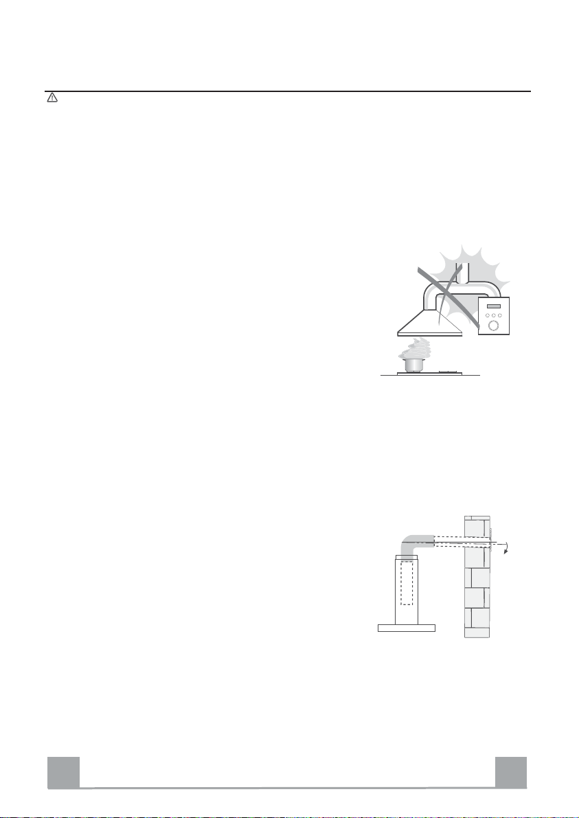
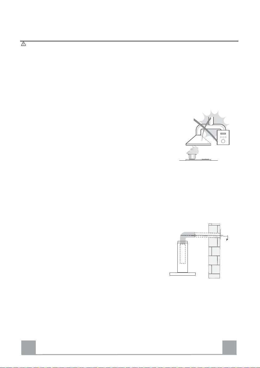
• Der min. Sicherheitsabstand zwischen Kochfeld
und Abzugshaube beträgt 650 mm (einige Modelle
können auch niedriger installiert werden; siehe
Absatz der Abstände und der Installation).
• Kontrollieren, ob die Netzspannung den Daten des
Typenschilds im Innern der Haube entspricht.
• Für Geräte der Klasse I muss kontrolliert werden,
ob das häusliche Versorgungsnetz korrekt geerdet
ist.
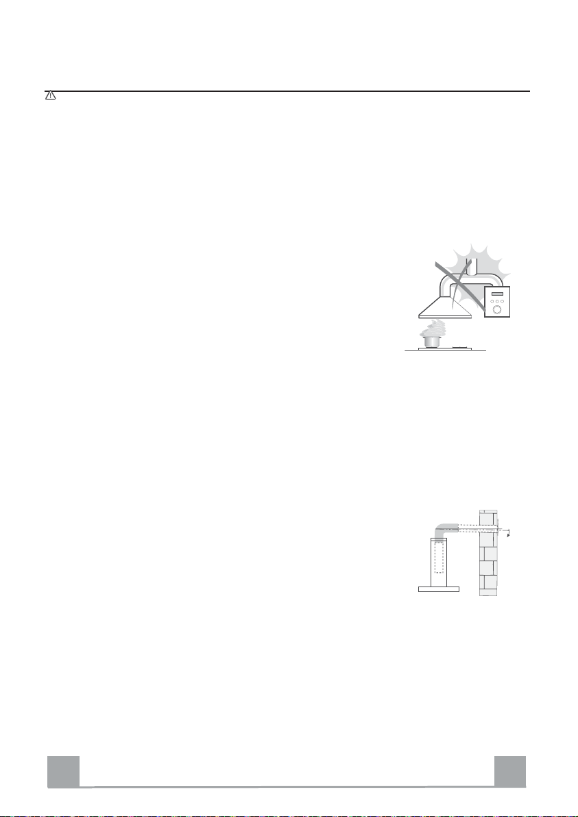
Die Absaughaube mit Hilfe eines Rohrs mit einem Mindestdurchmesser von
120 mm mit dem Rauchabzug verbinden. Der Verlauf des Rauchabzugs soll
so kurz wie möglich sein.
• Die Abzugshaube darf nicht an einen Schacht angeschlossen werden, in den
Rauchgase geleitet werden (z. B. von Heizkessel, Kaminen, usw.).
• Falls in dem Raum neben dem Abzug auch nicht
mit Strom betriebene Geräte (zum Beispiel
Gasgeräte) eingesetzt werden, muss für eine
ausreichende Belüftung gesorgt werden, damit der
Rückfluss der Abgase verhindert wird. Die Küche
muss eine direkte Öffnung nach Außen aufweisen,
damit ein ausreichender Luftaustausch
gewährleistet wird. Wird die Abzugshaube
zusammen mit nicht mit Strom betriebenen Geräte eingesetzt wird, darf der
Unterdruck im Raum 0,04 mbar nicht überschreiten, damit die Abgase nicht
wieder angesaugt werden.
• Schadhafte Kabel müssen durch den Hersteller oder vom Kundendienst
ausgewechselt werden, damit jedes Risiko ausgeschlossen wird.
2°
DE
4
4
• Falls die Montageanweisungen für die gasbetriebene Kochmulde einen
größeren Abstand vorschreiben, als der oben angegebene, muss diese
Vorgabe befolgt werden. Es sind sämtliche Abluftvorschriften zu beachten.
• Nur für die Abzugshaube geeignete Schrauben und Kleinteile verwenden.
Achtung: werden die Schrauben und Befestigungselemente nicht
entsprechend der vorliegenden Anleitungen verwendet, besteht
Stromschlaggefahr.
• Die Abzugshaube mittels zweipoligem Schalter mit einer Öffnung der
Kontakte von mindestens 3 mm an das Netz anschließen.
GEBRAUCH
• Die Abzugshaube wurde ausschließlich für den häuslichen Gebrauch
entwickelt, um Kochdünste zu beseitigen.
• Die Haube darf nur für die ihr zugedachten Zwecke benutzt werden.
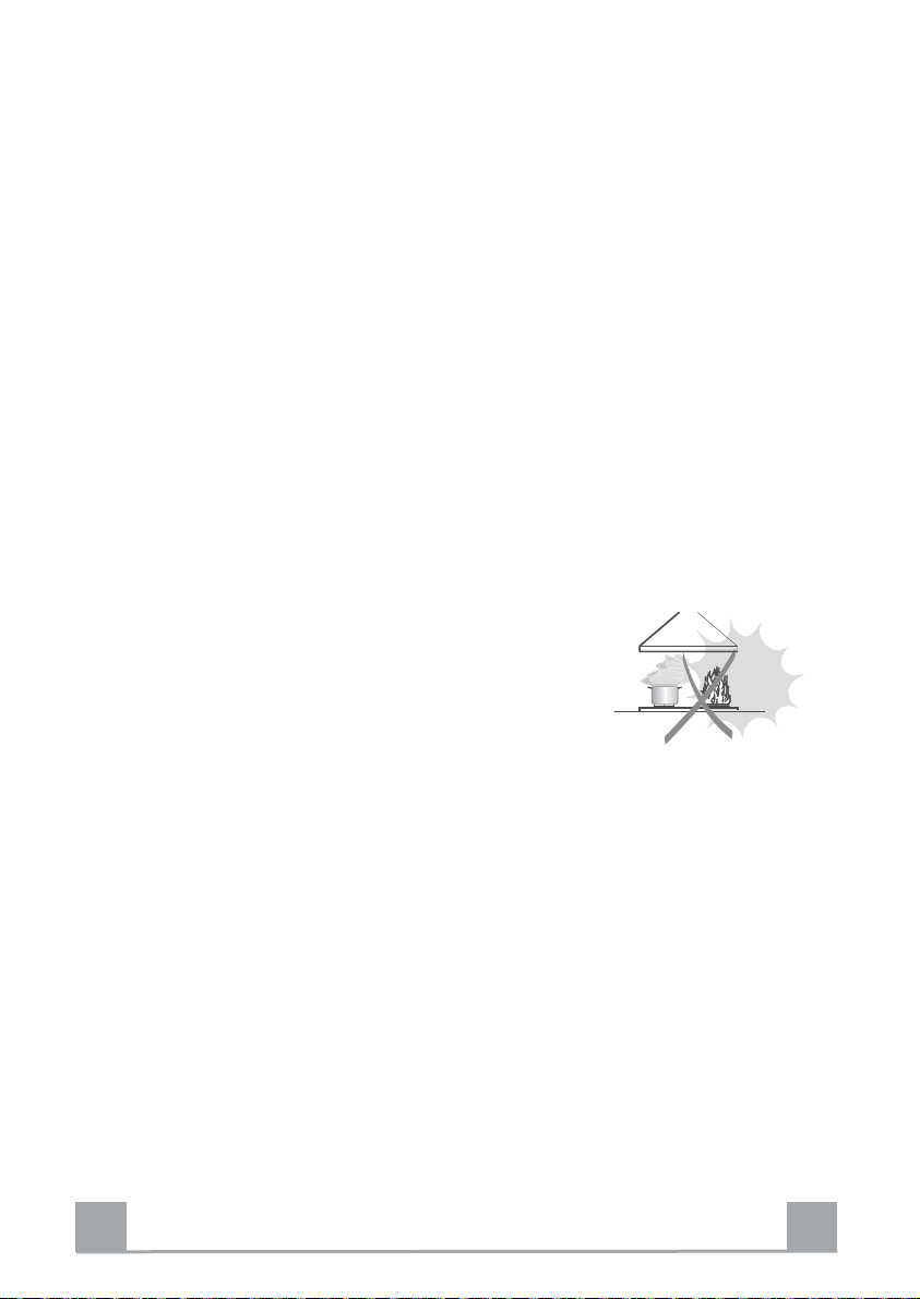
• Unter der eingeschalteten Haube keine offenen Flammen benutzen.
• Die Flamme so regulieren, dass sie nicht über den Boden des Kochgeschirrs
hinausreicht.
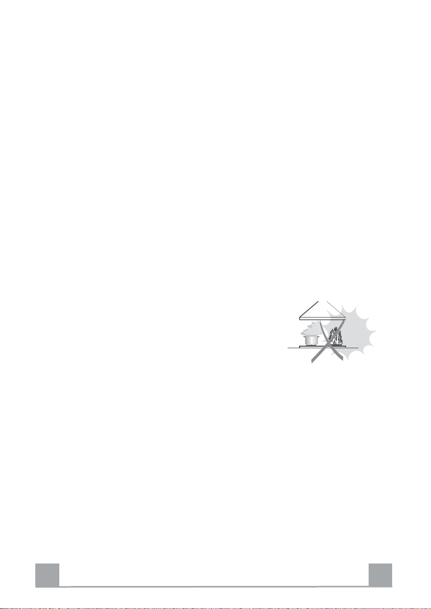
• Fritteusen müssen während des Gebrauchs
ständig überwacht werden: überhitztes Öl könnte
sich entzünden.
• Auf keinen Fall unter der Haube flambier en:
Brandgefahr.
• Kinder ab 8 Jahren und Personen mit
eingeschränkten physischen, sensorischen oder psychischen Fähigkeiten,
oder mit mangelnden Erfahrungen oder Kenntnissen dürfen nicht mit dem
Gerät umgehen, es sei denn, sie werden von einer für ihre Sicherheit
verantwortlichen Person beaufsichtigt oder angeleitet. Sicherstellen, dass
Kinder nicht mit dem Gerät herumspielen können. Reinigungs- und
Wartungsarbeiten dürfen nicht von unbeaufsichtigten Kindern durchgeführt
werden.
DE
5
5

•“ ACHTUNG: Die zugänglichen Teile können während des Gebrauchs der
Kochgeräte sehr heiß werden.
WARTUNG
• Vor Reinigungs- oder Wartungsarbeiten am Gerät muss dieses
ausgeschaltet und spannungslos gemacht werden.
• Die Filter stets nach den angegebenen Intervallen reinigen oder
auswechseln (Brandgefahr).
• Die Fettfilter sind alle 2 Monate oder bei intensiver Nutzung öfter zu reinigen
und können in der Spülmaschine JHVSOW werden.
• Der Aktivkohlefilter ist weder waschbar, noch regenerierbar und muss bei
normalem Betrieb zirka alle 4 Monate oder auch öfter ausgewechselt
werden, je nach Intensität des Gebrauchs.
• Die Haube mit einem feuchten Lappen und einem neutralen Reinigungsmittel
abwischen.
Das Symbol
das Gerät nicht als normaler Hausmüll entsorgt werden darf. Das ausrangierte
Gerät muss vielmehr bei einer speziellen Sammelstelle für elektrische und
elektronische Geräte abgegeben werden. Mit der vorschriftsmäßigen
Entsorgung des Gerätes trägt der Benutzer dazu bei, schädliche
Auswirkungen auf Umwelt und Gesundheit zu vermeiden. Weitere
Informationen zum Recycling dieses Produktes können bei der zuständigen
Behörde, der örtlichen Abfallbeseitigung oder bei dem Händler, der das Gerät
verkauft hat, eingeholt werden.
DE
am Produkt oder auf der Verpackung weist darauf hin, dass
6
6
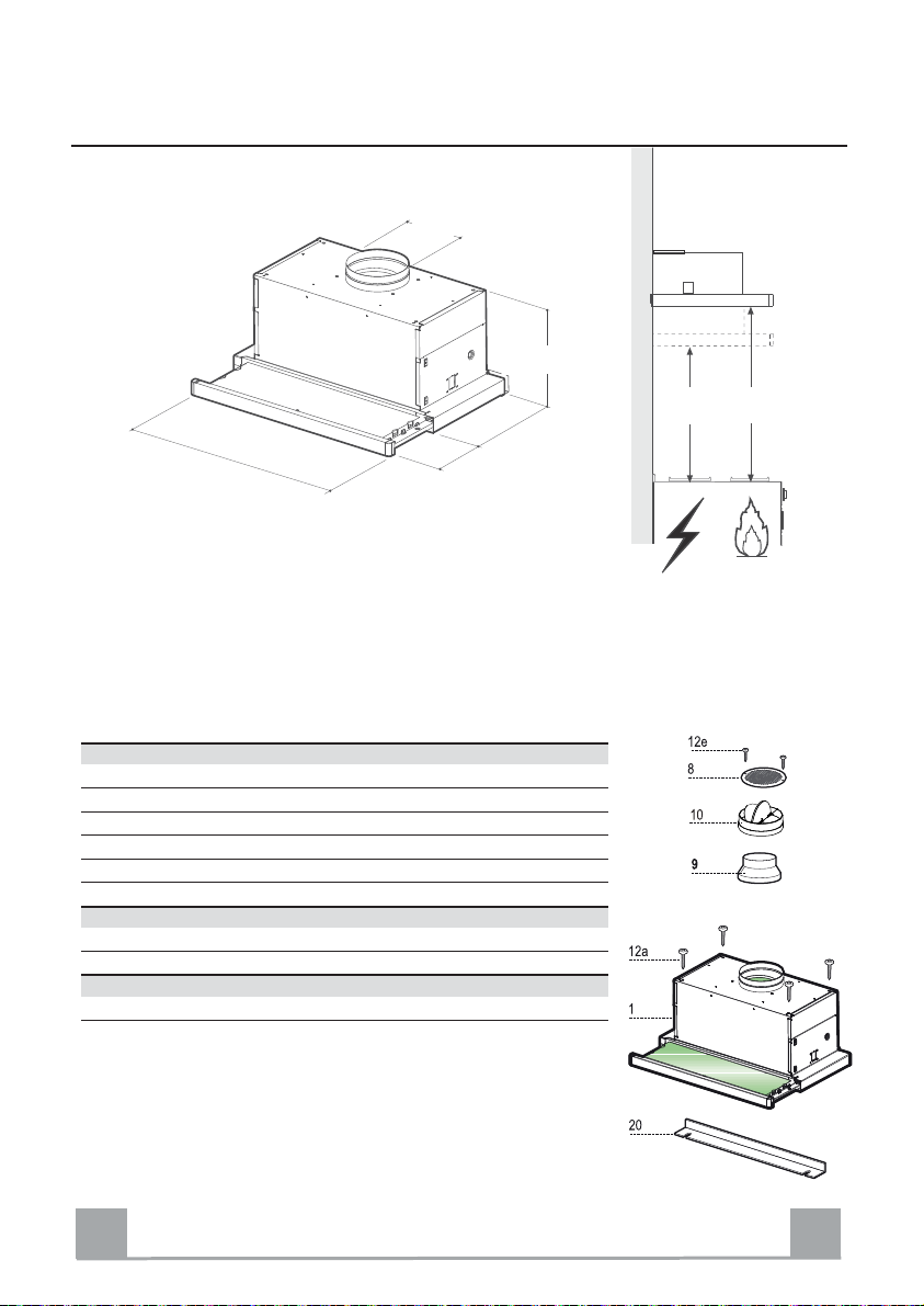
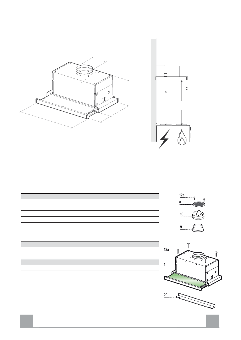
CHARAKTERISTIKEN
ø
150
260
598 - 898
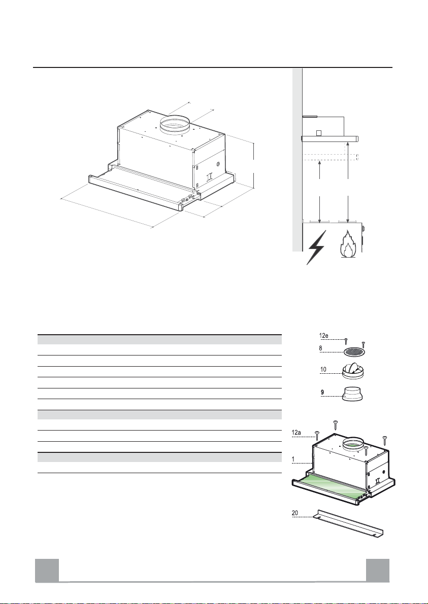
Komponenten
Pos. St. Produktkomponenten
1 1 Haubenkörper mit Schaltern, Beleuchtung, Gebläsegruppe, Filter
8 1 Luftleitgitter Luftaustritt
9 1 Reduzierflansch ø 150-120 mm
10 1 Flansch mit Ruckstauklappe
20 1 Abdeckprofil
280
152
÷
0
Min.
650mm
Min.
650mm
Pos. St. Montagekomponenten
12a 4 Schrauben 4,2 x 44,4
St. Dokumentation
1 Bedienungsanleitung
DE
7
7
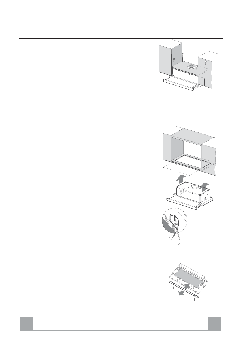
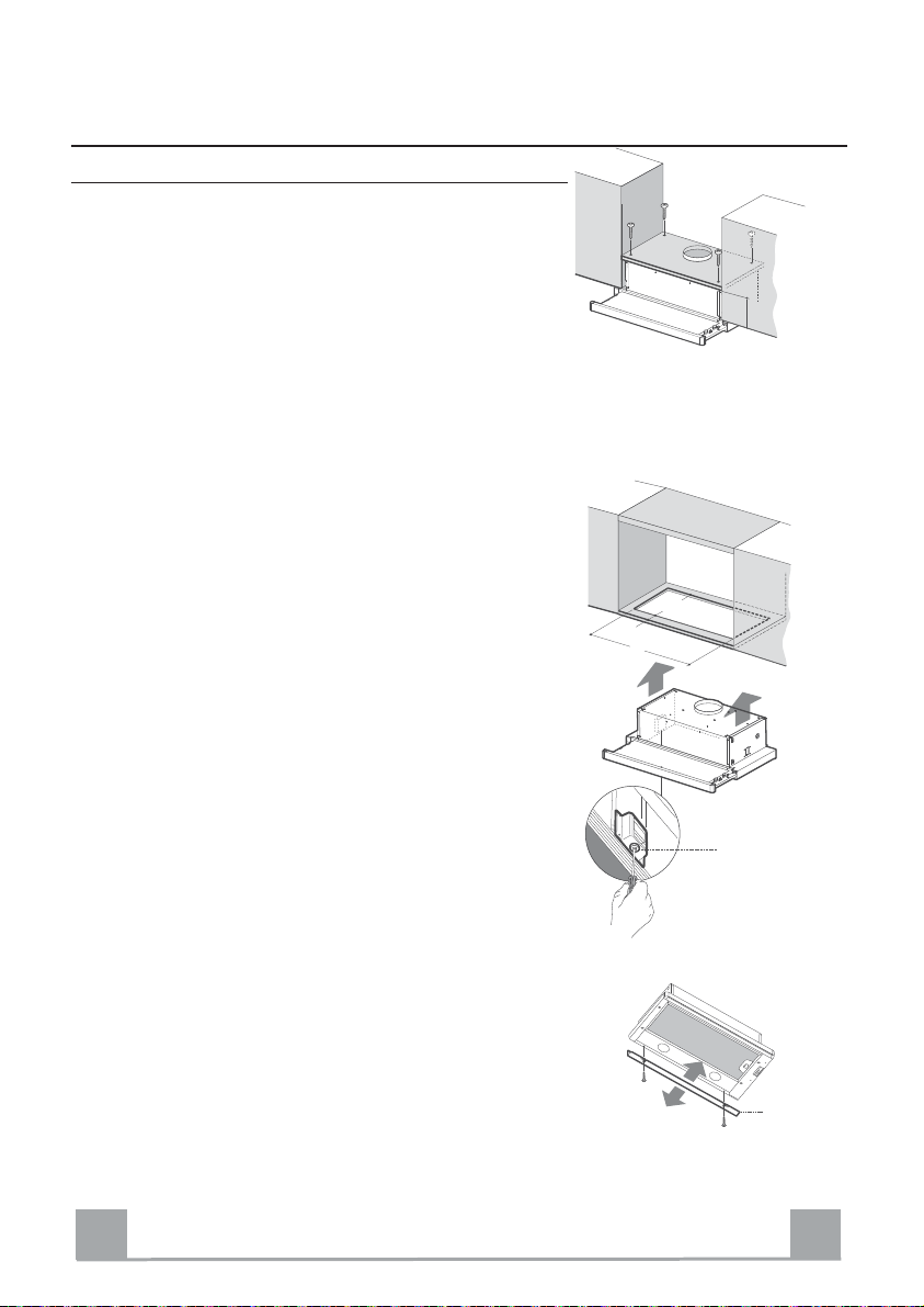
MONTAGE
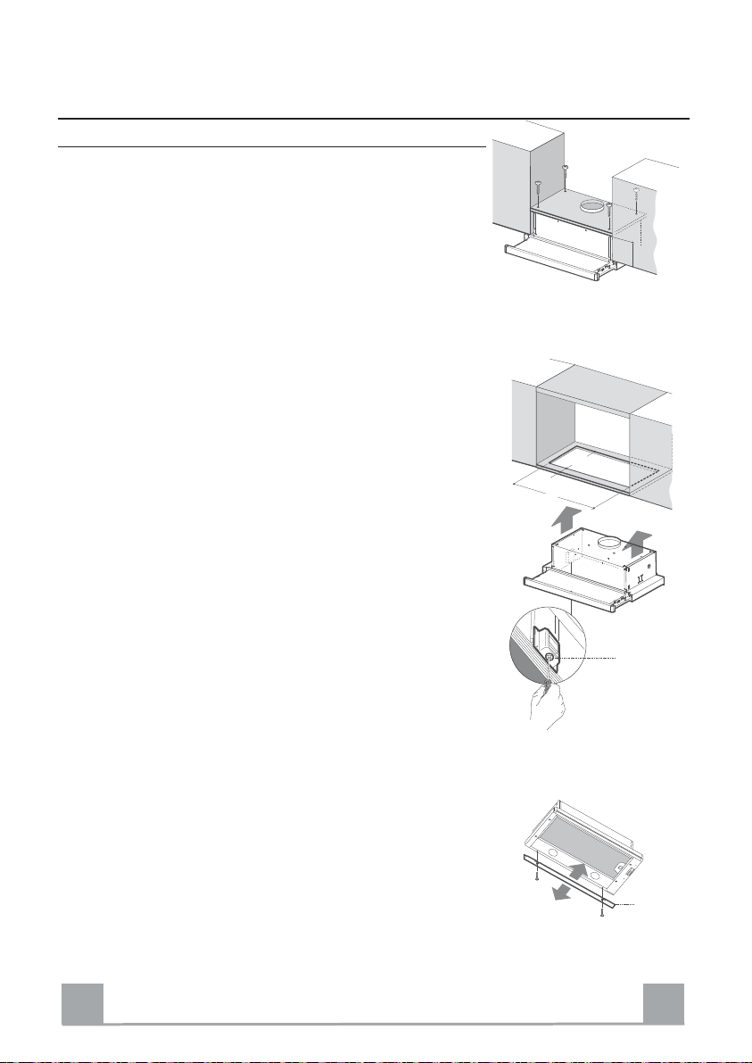
Bohren der Trägerplatte und Montage der Dunstabzugshaube
MONTAGE MIT SCHRAUBEN
Die Hauben-Trägerplatte muss 220 mm oberhalb der Ober-
•
schrank-Unterfläche positioniert werden.
•
Mit Hilfe des beiliegenden Bohrplanes Löcher ø 4,5 mm
latte bohren.
Trägerp
Mit Hilfe des beiliegenden Bohrplanes ein Loch ø 150 mm
•
die Träg
erplatte bohren.
•
Mit 4 der mitgelieferten Schrauben 12a (4,2 x 44,4) fixieren
MONTAGE MIT SCHNAPPVERSCHLUSS
Die Haube kann direkt an
•
der Oberschrank-Unterfläche mit
seitlichen Einrasthalterungen montiert werden.
•
Die Einbauvorrichtung laut Abbildung an der Unterseite des
Oberschrankes anbringen.
Die Haube einführen, bis die seitlichen Schn
•
appverschlüsse
einrasten.
•
Mit Hilfe der Schrauben Vf die Haube von der Unterseite her
definitiv fixieren.
in die
.
in
15
502 - 802
220
264
ABDECKPROFIL
Der Bereich zwischen Haubenkante und Rückw
•
es mitgelieferten Abdeckprofils 20 und der für diesen
Hilfe d
Zweck vorgesehenen Schrauben geschlossen werden.
DE
and kann mit
Vf
20
8
8
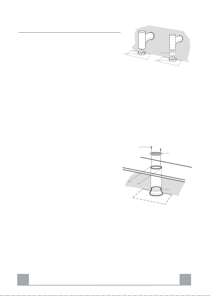
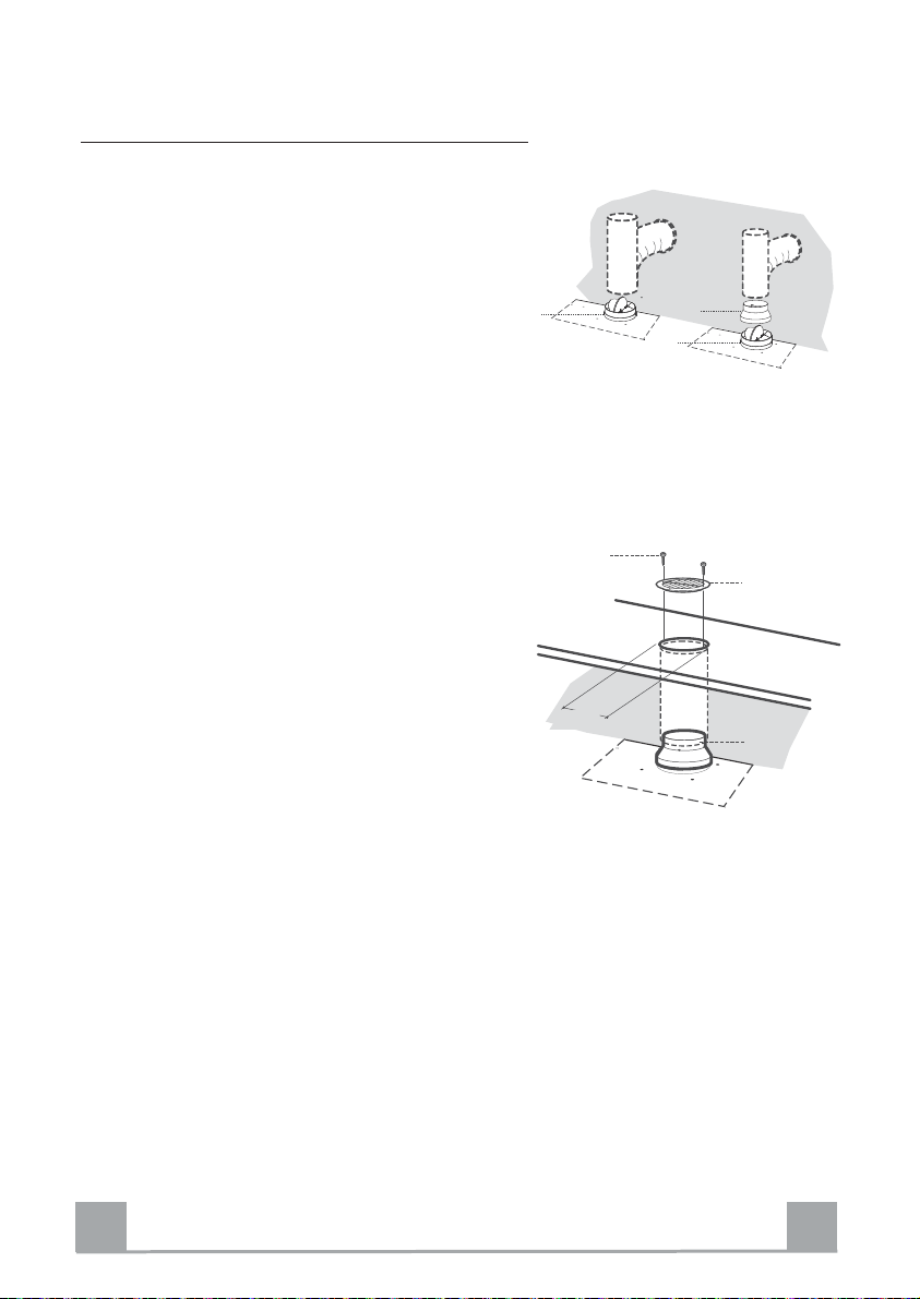
Anschluss
Anschluss Im Abluftbetrieb
Bei Abluftbetrieb kann die Haube vom Installateur wahlweise mittels Rohr oder Schlauch (ø150 oder 120mm)
an die Außenrohrleitung angeschlossen werden.
Anschlussrohres ø 150
• Den Flansch mit Ruckstauklappe 10 anbringen.
•
Das Rohr mit geeigneten Rohrschellen fixier
erforderliche Material wird nicht mitgelief
hierzu
Anschlussrohres ø 120
• Bei Verwendung eines Anschlussrohres ø 120 den
Reduzierflansch 9 am Flansch mit Ruckstauklappe
10 anbring
Das Rohr mit geeigneten Rohrschellen fixier
•
hierzu
•
Eventuell vorhandene Aktivkohlefilter entn
en.
erforderliche Material wird nicht mitgelief
en.Das
ert.
en.Das
ert.
ehmen.
ø 150
10
9
10
ø 120
Anschluss im Umluftbetrieb
In das eventuell über der Haube vorhandene Bord ein
•
125 mm bohren.
Loch ø
Reduzierflansch 9 am Haubenaustritt anbring
•Den
Den Flansch beim Luftaustritt am Bord oberhalb der
•
en.
12e
8
Haube mittels Rohr oder Schlauch ø120 mm an-
en.
schließ
Das Rohr mit geeigneten Rohrschellen fixieren
•
erforderliche Material wird nicht mitgelief
hierzu
Luftleitgitter 8 mit Hilfe von 2 der mitgelieferten
•Das
. Das
ert.
ø 125
9
Schrauben 12e (2,9 x 9,5) beim Austritt der rückzuführenden Luft fixier
Sicherstellen, dass der Aktivkohle-Geruchsfilter vor-
•
en.
handen ist.
ELEKTROANSCHLUSS
•
Bei Anschluss der Haube an das Stromnetz muss ein zweipoliger Schalter mit einem Öffnungsweg von mindestens 3 mm zwischengeschaltet werd
Nach Montage der Haube muss beim ersten Mal der Auszug energisch geöffnet we
•
bei
Erreichen des Endanschlages ein Klicken zu
hören ist.
en.
rden, bis
DE
9
9
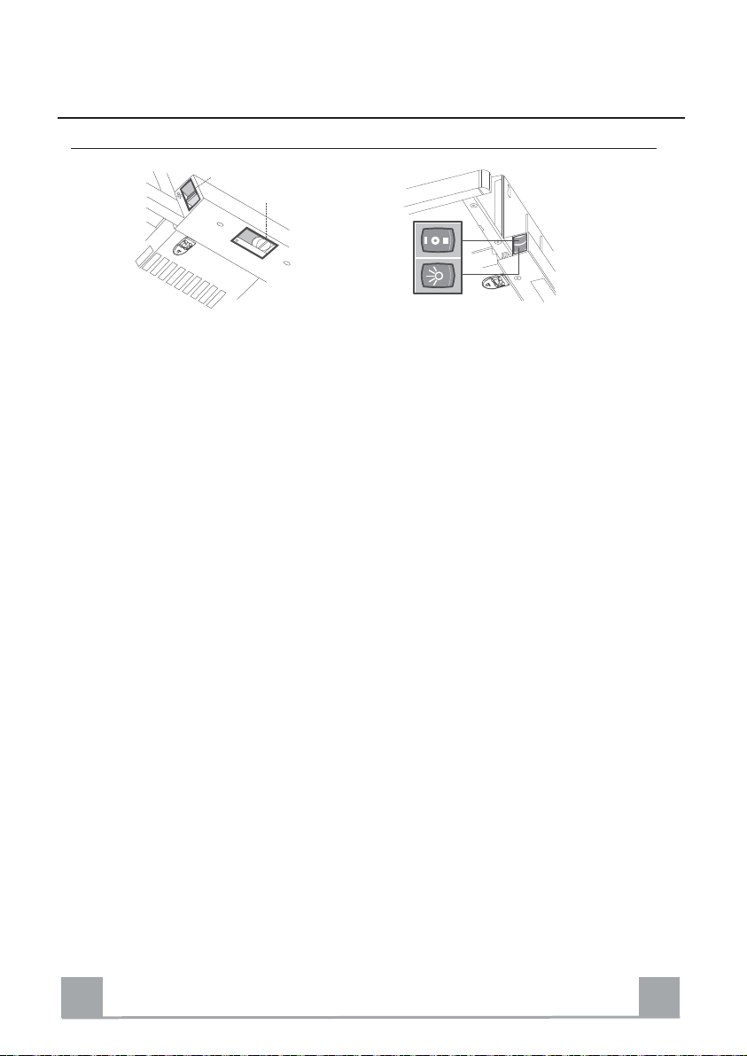
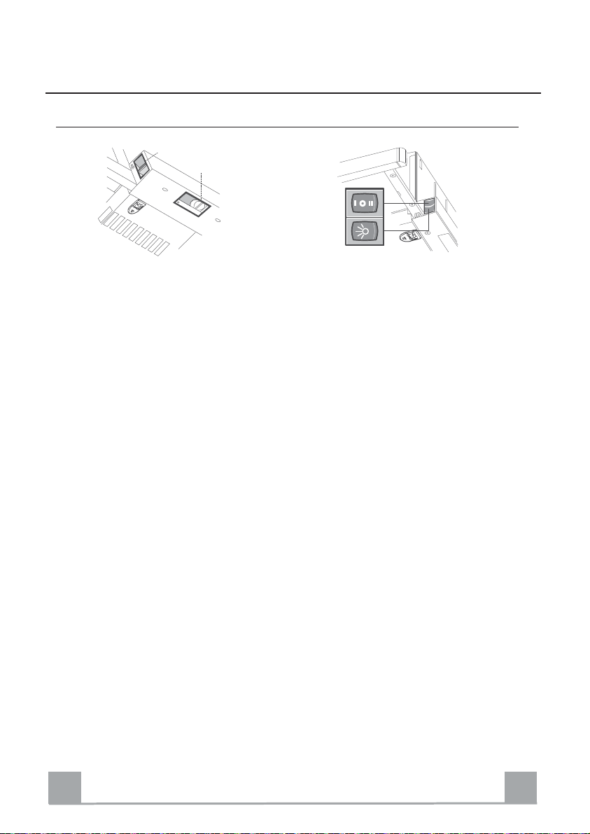
BEDIENUNG
Bedienfeld
L
0
1
M - V
0
1
2
3
M-V
L
L Beleu
cht. Schaltet die Beleuchtung ein
und aus.
M Motor Schaltet den Gebläsemotor
ein und aus.
V Geschw. bestimmt die Gebläsegech-
windigkeit und steuert folgende Geschwindigkeitsstufen:
1. geringste Gebläsestufe,
diese Stuf
ständigen
leisen
e ist für ein
und be
Luftaustausch bei
en
sonders
geringer Kochdunstentwicklung geeign
et.
2. mittlere Gebläsestufe,
eignet sich
guten Verh
und des
aufgr
ältnisses zwischen Fördervolumen und
Geräuschentwicklung für
die meisten Anw
endungs-
situationen.
t sich für
äsestufe,
starke
3. höchste Gebl
eigne
Kochdunstentwicklung,
auch üb
er längere zeith
L Beleu
cht. Schaltet die Beleuchtung ein
und aus.
M Motor Schaltet den Gebläsemotor
ein und aus.
V Geschw. bestimmt die Gebläsegech-
windigkeit und steuert folgende Geschwindigkeitsstufen:
1. geringste Gebläsestufe,
diese Stuf
ständigen
leisen
e ist für ein
und be
Luftaustausch bei
geringer Kochdunstentwicklung geeign
2.
mittlere Gebläsestufe,
eignet sich
guten Verh
aufgr
ältnisses zwischen Fördervolumen und
Geräuschentwicklung für
die meisten Anw
situationen.
in.
en
sonders
et.
und des
endungs-
DE
1
10
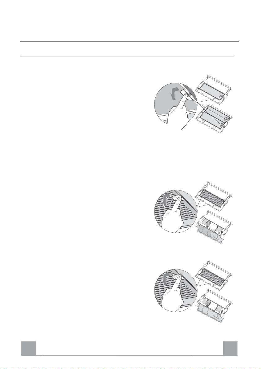
WARTUNG
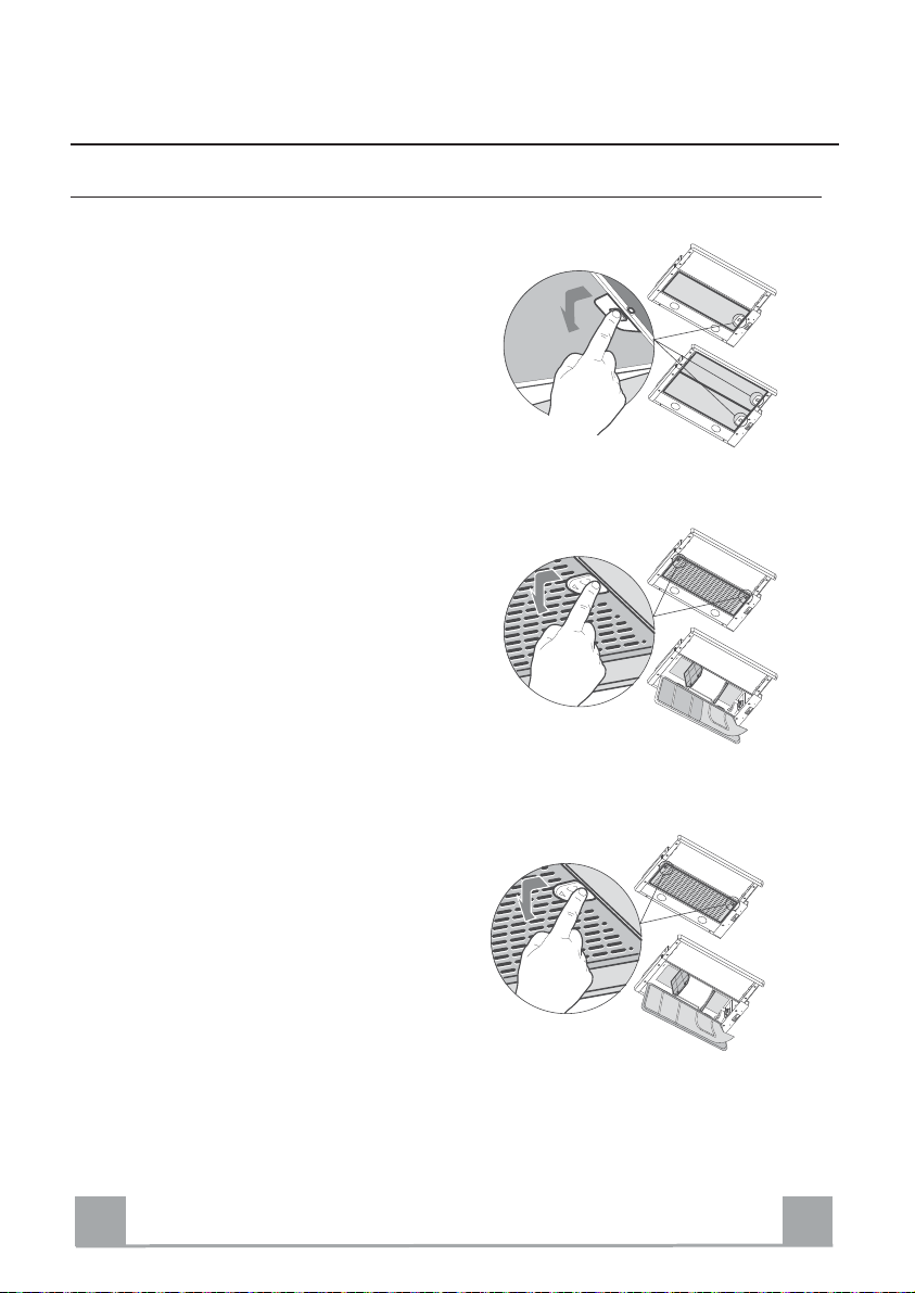
Fettfilter
SELBSTTRAGENDE METALLFETTFILTER - FILTERREINIGUNG
• Sie müssen nach 2-monatigem Betrieb bzw. Bei starkem Einsatz auch häufiger gereinigt werden, was im
Geschirrspüler
•
Die Filter einzeln entnehmen, indem die entsprechenden Haltevorrichtungen gelöst werden.
•
Die Filter reinigen (darauf achten, sie nicht zu verbiegen) und auf eine saugfähige Unterlage trocknen lassen. Den Fettfilter wieder einsetz
•
Es ist darauf zu achten, dass sich der Griff
sichtbar
•
Bei der Reinigung des Fettfilters in der Geschirrspülmaschine kann es je nach verwendetem Reiniger zu
bleibenden Verfärbungen kommen. Dies hat keinen
Einfluss auf die
•
Der Fettfilter kann auch mit einer Spülbürste und warmen Wasser, dem ein mildes Handspülmittel hinzugefügt wird, gereinigt werd
Sie müssen nach 2-monatigem Betrieb bzw. Bei star-
•
kem Einsatz auch häufiger gereinigt werden,
Geschirrspüler
Das Filterhaltegitter mit Hilfe der seitlichen Schiebe-
•
griffe aushaken
Filterhaltedraht entfernen.
•Den
Die Filter herausnehmen, spülen und vor der Remonta-
•
ge gut trocknen lassen.
• Die Filter mit Hilfe des Filterhaltedrahts wieder am
Haltegitter fixieren.
• Nach Anbringung der Filter das Filterhaltegitter wieder
schließ
•
Sie können weder gewaschen noch wiederverwendet werden und sind zumindest alle 2 Betriebsmonate bzw. bei starkem Einsatz auch häufiger auszutauschen.
•
Den Filterhalterahmen mit Hilfe der seitlic
Schiebegr
Filterhaltedraht
•Den
Den gesättigten Synthetikfi
•
Den neuen Filter mit Hilfe des Filterhaltedrahts fi-
•
xieren und den Halterahmen wieder schl
möglich
en Außenseite befind
möglich
.
en.
iffe au
ist.
en.
et.
Funktion des Fettfilters.
en.
MEHRSCHICHT-
ist.
SYNTHETISCHER FETTFILTER -
shaken.
lösen.
METALLFETTFILTER - FILTERREINIGUNG
lter auswechseln.
ießen.
auf der
was im
FILTERAUSTAUSCH
hen
DE
1
11

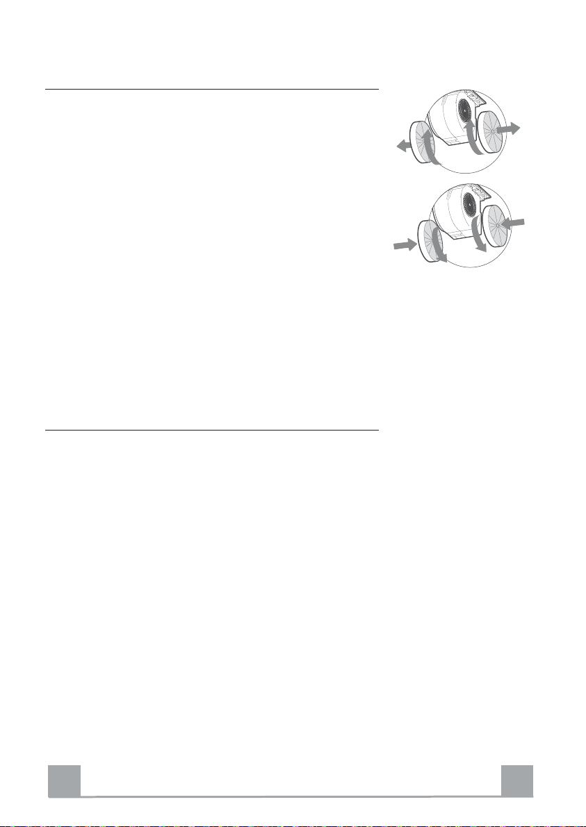
Geruchsfilter (Umluftbetrieb)
Sie können weder gewaschen noch wiederverwendet werden und
sind alle 4 Betriebsmonate bzw. bei starkem Einsatz auch häufiger auszutauschen.
AUSTAUSCHEN DER AKTIVKOHLE FILTER
• Die Metallfettfilter entnehme
Den gesättigten Aktivkohle-Geruchsfilter wie gezeigt entfer-
•
).
nen (A
•
Die neuen Filter wie gezeigt montieren (B).
Die Metallfettfilter wieder montie
•
• Die Kohlef
ilter können mit dem Hausmüll entsorgt werden.
n.
ren.
Beleuchtung
LED-Strahler
•
Für den Austausch der LED-Strahler wenden Sie si
Kundendienst.
ch bitte an den
A
B
Achtung: Dieses Gerät ist mit einer weißen LED-Lampe der Klasse 1M
gemäß EN 60825-1 ausgestattet: 1994 + A1:2002 + A2:2001; max.
gelieferte Lichtleistung @439nm: 7W. Nicht direkt mit optischen
Instrumenten (Fernglas, Lupe, usw.) in das Licht schauen.
DE
1
12
RECOMMENDATIONS AND SUGGESTIONS
The Instructions for Use apply to several versions of this appliance. Accordingly, you may find descriptions of individual features that do not apply to
your specific appliance.
INSTALLATION
• The manufacturer will not be held liable for any damages resulting from in-
correct or improper installation.
• The minimum safety distance between the cooker top
and the extractor hood is 650 mm (some models can
be installed at a lower height, please refer to the
paragraphs on working dimensions and installation).
• Check that the mains voltage corresponds to that indicated on the rating plate fixed to the inside of the
hood.
• For Class I appliances, check that the domestic
power supply guarantees adequate earthing.
Connect the extractor to the exhaust flue through a pipe of minimum diameter 120 mm. The route of the flue must be as short as possible.
• Do not connect the extractor hood to exhaust ducts carrying combustion
fumes (boilers, fireplaces, etc.).
• If the extractor is used in conjunction with nonelectrical appliances (e.g. gas burning appliances), a sufficient degree of aeration must be
guaranteed in the room in order to prevent the
backflow of exhaust gas. The kitchen must have
an opening communicating directly with the open
air in order to guarantee the entry of clean air.
When the cooker hood is used in conjunction with
appliances supplied with energy other than electric, the negative pressure in
the room must not exceed 0,04 mbar to prevent fumes being drawn back
into the room by the cooker hood.
• In the event of damage to the power cable, it must be replaced by the manufacturer or by the technical service department, in order to prevent any risks.
2°
EN
1
13
If the instructions for installation for the gas hob specify a greater di
•
specified above, this has to be taken into account. Regulations concerning
the discharge of air have to be fulfilled.
• Use only screws and small parts in support of the hood.
Warning: Failure to install the screws or fixing device in accordance with
these instructions may result in electrical hazards.
• Connect the hood to the mains through a two-pole switch having a contact
gap of at least 3 mm.
stance
USE
• The extractor hood has been designed exclusively for domestic use to elimi-
nate kitchen smells.
• Never use the hood for purposes other than for which it has been designed.
• Never leave high naked flames under the hood when it is in operation.
• Adjust the flame intensity to direct it onto the bottom of the pan only, making
sure that it does not engulf the sides.
• Deep fat fryers must be continuously monitored
during use: overheated oil can burst into flames.
• Do not flambè under the range hood; risk of fire.
• This appliance can be used by children aged from
8 years and above and persons with reduced
physical, sensory or mental capabilities or lack of
experience and knowledge if they have been given supervision or instruction
concerning use of the appliance in a safe way and understand the hazards
involved. Children shall not play with the appliance. Cleaning and user maintenance shall not be made by children without supervision.
EN
1
14

•“ CAUTION: Accessible parts may become hot when used with cooking ap-
pliances.”.
MAINTENANCE
• Switch off or unplug the appliance from the mains supply before carrying out
any maintenance work.
• Clean and/or replace the Filters after the specified time period (Fire hazard).
• The Grease filters must be cleaned every 2 months of operation, or more
frequently for particularly heavy usage, and can be washed in a dishwasher.
• The Activated charcoal filter is not washable and cannot be regenerated,
and must be replaced approximately every 4 months of operation, or more
frequently for particularly heavy usage.
• Clean the hood using a damp cloth and a neutral liquid detergent.
The symbol
may not be treated as household waste. Instead it shall be handed over to the
applicable collection point for the recycling of electrical and electronic equipment. By ensuring this product is disposed of correctly, you will help prevent
potential negative consequences for the environment and human health,
which could otherwise be caused by inappropriate waste handling of this
product. For more detailed information about recycling of this product, please
contact your local city office, your household waste disposal service or the
shop where you purchased the product.
on the product or on its packaging indicates that this product
EN
1
15
CHARACTERISTICS
ø
150
598 - 898
152
÷
0
Components
Ref. Q.ty Product Components
1 1 Hood Body, complete with: Controls, Light, Blower, Filters
8 1 Directional Air Outlet grille
9 1 Reducer Flange ø 150-120 mm
10 1 Dumper ø150 mm
20 1 Closing element
280
260
Min.
650mm
Min.
650mm
Ref. Q.ty Installation Components
12a 4 Screws 4,2 x 44,4
12e 2 Screws 2,9 x 9,5
Q.ty Documentation
1 Instruction Manual
EN
1
16
INSTALLATION
Drilling the Support surface and Fitting the Hood
SCREW FITTING
The hood support surface must be 220 mm above the bottom
•
surface of the wall units.
•
Drill the support with a ø 4,5 mm drill bit, using the drilling
template provided.
Cut a hole ø 150 mm in size on the support surface, using the
•
drilling template provided.
•
Fix using the 4 screws 12a (4,2 x 44,4) provided.
SNAP-ON FITTING
The hood can be installed either directly on the bottom surface
•
of the wall units using snap-on side supports.
•
Cut a fitted opening in the bottom surface of the wall unit, as
shown.
• Insert the hood until the side supports snap into place.
• Lock in position by tightening the screws Vf from underneath
the hood
.
15
502 - 802
220
264
CLOSING ELEMENT
The space between the edge of the hood and the rear wall can
•
be closed by applying the element 20 provided, using the
screws supplied for this purpose.
EN
Vf
20
1
17

Connections
DUCTED VERSION AIR EXHAUST SYSTEM
When installing the ducted version, connect the hood to
the chimney using either a flexible or rigid pipe ø 150
or 120mm, the choice of which is left to the installer.
To install a ø 150 pipe
To install the dumper 10
•
•
Fix the pipe in position using sufficient pipe
(not supplied).
To install a
To install a ø 120 mm
•
the r
•
Fix the pipe in position using sufficient pipe
ø 120 pipe
air exhaust connection, insert
educer flange 9 on the dumper 10
(not supplied).
Remove any activated charcoal filters.
•
clamps
.
clamps
ø 150
10
9
10
ø 120
RECIRCULATION VERSION AIR OUTLET
•
Cut a hole ø 125 mm in any shelf that may be positioned over the h
Insert the reducer flange 9 on the hood body
•
Connect the flange to the outlet on the shelf over the
•
hood by using a flexible or rigid pipe ø120
Fix the pipe in position using sufficient pipe
•
ood.
outlet.
mm.
clamps
(not supplied).
Fix the air outlet grid 8 on the recirculation air outlet
•
by using the 2 screws 12e (2,9 x 9,5) provide
Ensure that the activated charcoal filters have been
•
inserted
.
d.
ø 125
12e
8
9
ELECTRICAL CONNECTION
Connect the hood to the mains through a two-pole switch having a contact gap of
•
at least 3
mm.
•
When opening the sliding carriage for the first time after installing the hood, pull it out
briskly until it cl
icks.
EN
1
18
USE
Control panel
L
0
1
Light Switches the lighting system
L
on and off.
M Motor Switches the extractor motor
on and off.
V Speed Sets the operating speed of
the extractor:
Low speed, used for
1.
continuous
change in the presence of
light cooking vapour.
2. Medium speed, suitable
for most operating conditions giv
treated air flow/noise
level ratio.
3.
Maximum speed, used
eliminating the highest
cooking vapour emission,
including long periods.
M - V
0
1
2
3
and silent air
en the optimum
M-V
L
L Light Switches the lighting system
on and off.
M Motor Switches the extractor motor
on and off.
V Speed Sets the operating speed of
the extractor:
a
1. Low speed, used for a
continuous
change in the presence of
light cooking vapour.
2. Medium speed, suitable
for most operating conditions giv
en the optimum
treated air flow/noise
level ratio.
for
and silent air
EN
1
19
MAINTENANCE
Grease filters
CLEANING METAL SELF-SUPPORTING GREASE FILTERS
•
The filters must be cleaned every
of operation
age, and can be washed in a di
Remove the filters one at a time, after discon-
•
necting the relative fastening elem
Wash the filters, taking care no
•
Allow them
When refitting the filters, make sure that the
•
handle is visible
, or more frequently with heavy us-
to dry before refittin
on the outside.
two months
shwasher.
ents.
t to bend them.
g.
CLEANING MULTILAYER METAL
•
The filters must be cleaned every
of operation
age, and can be washed in a dishwasher.
• Release the filter retaining grill using the lateral
sliding ha
Remove the filter retaining
•
Remove and wash the filters. Allow them to dry
•
before refitting.
Replace the filters on the grill, fix them in posi-
•
tion using the filter retaining clips and close th
filte
•
The filter is not washable and cannot be regenerated, and must be replaced approximately every two months of use, or more frequently
with heavy usag
•
Release the filter holder frame using the lateral
sliding ha
Remove the fIlter retaining
•
Replace the saturated synthetic filter
•
•
Fix the new synthetic filter using the retaining
clips and close the filter holder fram
, or more frequently with heavy us-
ndles.
clips.
r retaining grill
ndles.
.
REPLACING SYNTHETIC GREASE FILTER
e.
clips.
two months
.
e.
GREASE FILTERS
e
EN
2
20
Activated charcoal filter (Recirculation version)
These filters are not washable and cannot be regenerated, and
must be replaced approximately every 4 months of operation, or
more frequently with heavy usage.
REPLACING THE ACTIVATED CHARCOAL FILTER
A
• Remove the metal grease filter
Remove the saturated activated charcoal filter as shown (A
•
Fit the new filters (B
•
•
Replace the metal grease filters.
).
s
).
Lighting unit
Warning: This appliance is fitted with a white LED lamp classed
as 1M according to EN 60825-1: 1994 + A1:2002 + A2:2001
standards; maximum optical power emitted @439nm: 7W. Do
not look directly at the light through optical devices (binoculars,
magnifying glasses…).
For replacement contact technical support. ("To purchase con-
•
tact technical support")
B
EN
2
21
CONSEILS ET SUGGESTIONS
Les instructions pour l’utilisation se réfèrent aux différents modèles de cet
appareil. Par conséquent, certaines descriptions de caractéristiques
particulières pourraient ne pas appartenir spécifiquement à cet appareil.
INSTALLATION
• En aucun cas le fabricant ne peut être tenu pour responsable d’éventuels
dommages dus à une installation ou à une utilisation impropre.
• La distance de sécurité minimum entre le plan de
cuisson et la hotte aspirante est de 650 mm (certains
modèles peuvent être installés à une hauteur inférieure ;
voir le paragraphe concernant les dimensions de travail
et l’installation).
• Assurez-vous que la tension de votre secteur correspond
à celle indiquée sur la plaque des données appliquée à
l’intérieur de la hotte.
• Pour les appareils de Clas se I, s’assurer que l’installation électrique de votre
intérieur dispose d’une mise à la terre adéquate.
Relier l’aspirateur au conduit de cheminée avec un tube d’un diamètre minimum
de 120 mm. Le parcours des fumées doit être le plus court possible.
• Ne pas relier l a hotte aspirante aux condui ts de cheminée qui acheminent les
fumées de combustion (par exemple de chaudières, de cheminées, etc.).
• Si vous utilisez l’aspirateu r en combinaison avec des
appareils non électriques (par ex. appareils à gaz), vous
devez garantir un degré d’aération suffisant dans la pièce,
afin d’empêcher le retour du flux des gaz de sortie. La
cuisine doit présenter une ouverture communiquant
directement vers l’extérieur pour garantir l’amenée d’air
propre. Si vous utilisez la hotte de cuisine en combinaison avec des appareils
non alimentés à l’électricité, la pression négative dans la pièce ne doit pas
dépasser 0,04 mbar afin d’éviter que la hotte ne réaspire les fumées dans la
pièce.
• Si le cordon d’ alimentation est endommagé, veuillez le faire remplacer par le
fabricant ou par un service après-vente agréé pour éviter tout risque d’accident.
2°
FR
2
22
Si les instructions d’installat
•
distance supérieure à celle indiquée ci-dessus, veuillez impérativement en
tenir compte. Toutes les normes concernant l’évacuation de l’air doivent être
respectées.
• Utiliser exclusivement des vis et des petites pièces du type adapté pour la
hotte.
Attention : toute installation des vis et des dispositifs de fixation non
conforme aux présentes instructions peut entraîner des risques de
décharges électriques.
• Brancher la hotte à l’alimentation de secteur avec un interrupteur bipolaire
ayant une ouverture des contacts d’au moins 3 mm.
ion du plan de cuisson à gaz spécifient une
UTILISATION
• Cette hotte aspirante a été conçue exclusivement pour un usage
domestique, dans le but d’éliminer les odeurs de cuisine.
• Ne jamais utiliser la hotte pour des objectifs différents de ceux pour lesquels
elle a été conçue.
• Ne jamais laisser un feu vif allumé sous la hotte lorsque celle-ci est en
fonction.
• Régler l’intensité du feu de manière à l’orienter exclusivement vers le fond
de la casserole, en vous assurant qu’il ne déborde pas sur les côtés.
• Contrôler constamment les friteuses durant leur
utilisation : l’huile surchauffée risque de s’incendier.
• Ne pas flamber des mets sous la hotte : sous risque
de provoquer un incendie.
• Cet appareil n’est pas destiné à être utilisé par des
enfants d’un âge inférieur à 8 ans, ni par des personnes dont les capacités
physiques, sensorielles ou mentales sont diminuées ou qui ont une
expérience et des connaissances insuffisantes, à moins que ces enfants ou
ces personnes ne soient attentivement surveillés et instruits sur la manière
d’utiliser cet appareil en sécurité et sur les dangers que cela comporte.
Assurez-vous que les enfants ne jouent pas avec cet appareil. Le nettoyage
et l’entretien de la part de l’utilisateur ne doivent pas être effectués par des
enfants, à moins que ce ne soit sous la surveillance d’une personne
responsable.
FR
2
23

• ATTENTION : les parties accessibles peuvent devenir très chaudes durant
l’utilisation des appareils de cuisson.
ENTRETIEN
• Avant d’effectuer toute opération de nettoyage et d’entretien, éteindre ou
débrancher l’appareil du secteur.
• Nettoyer et/ou remplacer les filtres après le délai indiqué (danger
d’incendie).
• Nettoyer les filtres à graisse tous les 2 mois de fonctionnement ou plus
souvent en cas d’utilisation particulièrement intense. Ces filtres peuvent être
lavés au lave-vaisselle.
• Le filtre à charbon actif ne peut être ni lavé ni régénéré et il doit être
remplacé environ tous les 4 mois de fonctionnement ou plus souvent en cas
d’utilisation particulièrement intense.
• Nettoyer la hotte avec un chiffon humide et un détergent liquide neutre.
Le symbole
produit ne peut pas être éliminé comme déchet ménager normal. Lorsque ce
produit doit être éliminé, veuillez le remettre à un centre de collecte prévu pour
le recyclage du matériel électrique et électronique. En vous assurant que cet
appareil est éliminé correctement, vous participez à prévenir des
conséquences potentiellement négatives pour l'environnement et pour la
santé, qui risqueraient de se présenter en cas d’élimination inappropriée. Pour
toute information supplémentaire sur le recyclage de ce produit, contactez
votre municipalité, votre déchetterie locale ou le magasin où vous avez acheté
ce produit.
FR
marqué sur le produit ou sur son emballage indique que ce
2
24
CARACTERISTIQUES
ø
150
260
598 - 898
Composants
Réf. Q.té Composants de Produit
1 1 Corps Hotte équipé de:Comandes, Lumière, Groupe Ventilateur,
Filtres
8 1 Grille en Direction Sortie Air
9 1 Flasque de Réduction ø 150-120 mm
10 1 Buse avec clapet
20 1 Profil fermeture
280
152
÷
0
Min.
650mm
Min.
650mm
Réf. Q.té Composants pour l ’installation
12a 4 Vis 4,2 x 44,4
Q.té Documentation
1 Manuel d’instructions
FR
2
25
INSTALLATION
Perçage du Plan de support et Montage de la Hotte
MONTAGE AU MOYEN DE VIS
Le Plan de support de la Hotte doit êtr
•
de 220 mm. par rapport au Plan inférieur des Armoires murales.
Percer un trou de ø 4,5 mm. sur le support, en utilisant le
•
Gabarit de perçage fourni avec l’appareil.
• Percer un trou de ø 150 mm. sur le Plan de support, en uti-
lisant le Gabarit de perçage fourni avec l’appareil.
Fixer à l’aide des 4 Vis 12a (4,2 x 44,4) fournies avec
•
l’appareil.
MONTAGE AVEC FIXATION PAR ENCLIQUETAGE
Il est possible d’installer la Hotte directement sur le plan
•
inférieur des Armoires murales au moyen de supports latéraux par encliquetage.
Effectuer un emboîtage sur le plan inférieur de
•
murale, comme indiqué.
•
Insérer la Hotte jusqu’à accrocher les Supports latéraux par
encliquetage.
Bloquer définitivement en serrant les Vis Vf depuis le bas
•
de la Hotte.
e monté plus en haut
l’Armoire
15
502 - 802
220
264
PROFIL DE FERMETURE
Il est possible de boucher l’espace entre le rebord de la
•
Hotte et la Paroi du fond, en appliquant le Profil 20 fourni
avec l’appareil, à l’aide des Vis déjà prévus à cet effet.
FR
Vf
20
2
26
Branchements
SORTIE AIR VERSION ASPIRANTE
En cas d’installation en version aspirante, brancher la
hotte à la tuyauterie de sortie via un tube rigide ou
flexible de ø 150 ou 120 mm, au choix de l’installateur.
Branchement avec un tube de ø150
Insérer la buse avec clapet 10
•
Fixer le tube par des colliers appropriés. Le matériau
•
nécessaire n’est
Branchement a
Insérer le flasque de réduction 9 sur la buse avec cla-
•
.
pet 10
•
Fixer le tube par des colliers appropriés. Le matériau
nécessaire n’est
Retirer les éventuels filtres anti-odeur au charbon
•
pas fourni.
vec un tube de ø120
pas fourni.
actif.
.
ø 150
10
9
10
ø 120
SORTIE AIR VERSION FILTRANTE
•
Percer un trou de ø 125 mm. sur l’éven
qui se
trouve au-d
Insérer le flasque de réduction 9
•
essus de la Hotte.
tuelle Tablette
sur la sortie du corps
12e
8
de la hotte.
• Connecter la Flasque au trou de sortie sur la Tab
qui se trouve
tuyau rigide ou flexible de ø120
Fixer le tube par des colliers appropriés. Le matériau
•
nécessaire n’est
Fixer la Grille orientée 8 sur la sortie de l’air recyclé
•
au-dessus de la Hotte, au moyen d’un
mm.
pas fourni.
lette
ø 125
9
à l’aide de 2 Vis 12e (2,9 x 9,5) fournies avec
l’appareil
•
S’assurer de la présence des filtres anti-odeur au
.
charbon actif.
BRANCHEMENT ELECTRIQUE
Brancher la hotte sur le secteur en interposant un interrupteur bipolaire avec ouv
•
erture des
contacts d’au moins 3 mm.
• Après avoir installé la hotte, il est indispensable pour la première fois d’ouvrir le ch
coulissant de façon énerg
ique, jusqu’à ce que l’on entende le déclic de fin de cour
se.
ariot
FR
2
27
 Loading...