

Page 1
KÖNIG & MEYER GmbH & Co. KG
Kiesweg 2, 97877 Wertheim, www.k-m.de
15910-000-55 Rev.04 03-80-318-00 01/15
TECHNISCHE DATEN / SPEZIFIKATION
AUFSTELLANLEITUNG
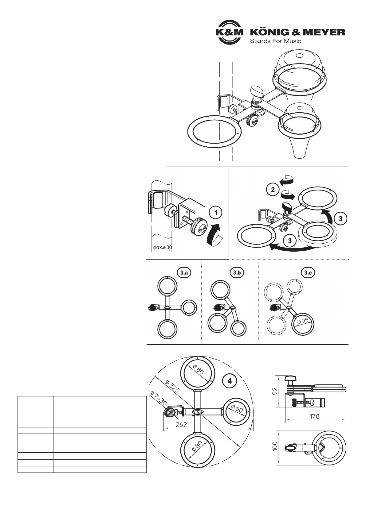
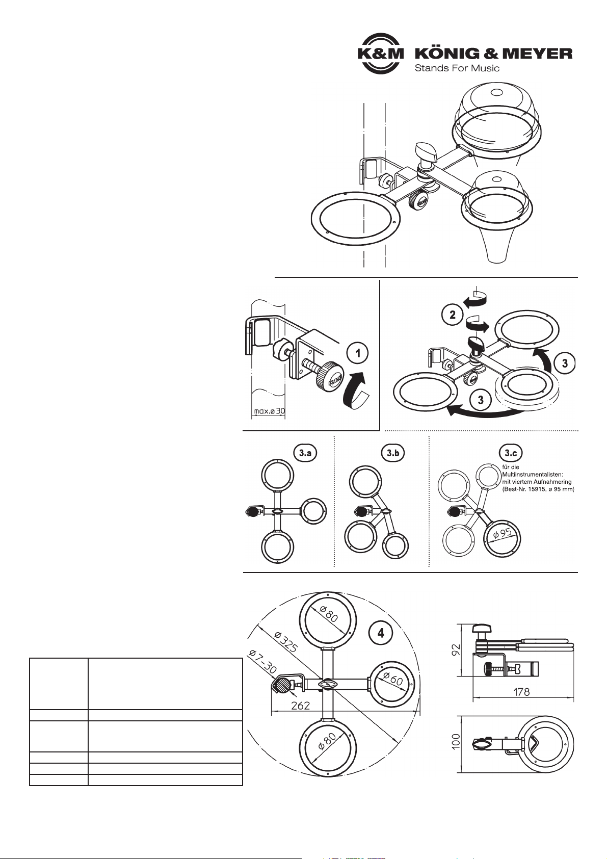
15910 Dämpferhalter
Hochwertig und flexibel
- trägt bis zu 3 Dämpfer für Trompete, Kornett und Flügelhorn
- Dämpferaufnahmen gummiummantelt
- vielseitig verstellbar und leicht zu bedienen
- anklemmbar an Stative von bis zu 30mm Durchmesser
- zusammenklappbar und leicht zu transportieren
SICHERHEITSHINWEISE
Vielen Dank, dass Sie sich für dieses Produkt entschieden haben.
Diese Anleitung informiert Sie über alle wich tigen Schritte bei Aufbau
und Handhabung.Wir empfehlen, sie auch für den späteren Gebrauch
aufzubewahren.
REINIGEN
Zur Reinigung am besten ein leicht feuchtes Tuch
und ein nicht scheuerndes Reinigungsmittel benutzen.
FEHLERSUCHE (F) und BESEITIGUNG (B)
F: Installation sieht "schief" aus
F. B: Verschraubungen fest anziehen
F: Stativ neigt zum Kippen
F. B: Eignung des Stativs überprüfen
F. B: Ausbalancieren der Lasten am Stativ (siehe: 3.b)
Halterung zusammenbauen
Das Produkt ist bereits komplett vormontiert.
BEFESTIGUNG der Halterung am Stativ
1 Das Klemmprisma passt an Rohre bis zu 30 mm.
1 Das Prisma wird um das Rohr geführt und durch
1 Anziehen der Rändelschraube befestigt.
AUSRICHTUNG der Dämpferhalter
2 Flügelmutter nur leicht lösen.
3 Dämpferringe in Position drehen und diese durch
3 festes Anziehen der Flügelmutter sichern 2.
OPTIONEN
3.a weite Abstände - guter Zugriff, schöne Optik
3.b möglichst nah am Stativrohr - empfohlen bei
3.b leichten Stativen aus Gründen der Standsicherheit
3.c weiterer Aufnahmering 15915 - für vierten Dämpfer
EINLEGEN der Dämpfer
4 Die Dämpfer in den jeweils am besten
4 geeigneten Ring einlegen (siehe Abm.)
- Die verwendeten Stative sind bezüglich Tragkraft
- und Standfestigkeit auf ihre Eignung zu prüfen.
- Die Möglichkeit das Produkt zusammenzuklappen birgt
- naturgemäß Einklemmgefahren: umsichtige Handhabung
- bei Aufbau, Betrieb und Abbau sind daher unverzichtbar
- Nur für Dämpfer; andere Lasten sind nicht erlaubt
- Schadhafte Teile dürfen nicht mehr verwendet
- werden und sind zu ersetzen.
Material
Prisma, Haltewinkel, Bügel:
Stahl, pulverbeschichtet, schwarz
Verschraubung: Stahl, verzinkt
Griff, Kappen: Kunststoff (PA)
Gummierung: Kunststoff (TPE)
Traglast Dämpfer
Abmessungen
Ringe: 2 x ø 80 mm, 1 x ø 60 mm
Prisma: ø 7-30 mm
Klappmaß: 92 x 100 x 178 mm
Gewicht 0,3 kg
Verpackung Polybeutel 200 x 270 mm
Zubehör Vierter Ring ø 95 mm, Best.-Nr. 15915
BEFESTIGUNG
OPTIONEN
AUSRICHTUNG
EINLEGEN & ABMESSUNGEN PACKMASS
für die Optik:
gleichmäßig
verteilt
für die
Standfestigkeit:
möglichst nah
am Stativrohr
für die
Multiinstrumentalisten:
mit viertem Aufnahmering
(Best-Nr. 15915, ø 95 mm)
AUFNAHMERING
Best.-Nr. 15915
Die Halterung kann für Transport
und/oder Lagerung sehr kompakt
zusammengelegt werden
Page 2
für die
Multiinstrumentalisten:
mit viertem Aufnahmering
(Best-Nr. 15915, ø 95 mm)
KÖNIG & MEYER GmbH & Co. KG
Kiesweg 2, 97877 Wertheim, www.k-m.de
15910-000-55 Rev.04 03-80-318-00 01/15
TECHNICAL DATA
SETUP INSTRUCTIONS
15910 Mute holder
High quality and flexible
- holds up to 3 mutes for trumpets, cornets and Flugelhorns
- mute holders are rubberized
- flexible and easy to adjust and operate
- attaches to stands with diameters of up to 30 mm
- the holder collapses, has a small footprint and is easy to transport
SAFETY NOTES
Thank you for choosing this product. The instructions provide directions
to all of the important set up and handling steps. We recommend you
keep these instructions for future reference.
MAINTENANCE
To care for the product use a damp cloth
and a non-abrasive cleaning agent.
FAULT-FINDING (F) and REPAIR (R)
F: Installation looks like its tilting
F. R: Tighten the clamp
F: The stand is lilting to one side
F. R: Check to ensure that the stand is suitable for the load
F. R: Balance the loads on the stand (see 3.b)
Assemble the holder
The product comes completely pre-assembled.
ATTACHING the holder to the stand
1 The clamp prisma is equipped for tubes up to 30mm.
1 The prismatic clamp is threaded through the tube and
1 is attached by tightening the finger screw.
ADJUSTMENT of the mute holders
2 Loosen the wing nuts a bit.
3 Place the mute rings in the desired position
3 and tighten the wing nuts 2.
OPTIONS
3.a wide distances - easy access - attractive appearance
3.b placement as close to the stand as possible is
3.b recommended for light stands for safety reasons
3.c additional Mute Holder 15915 - for a fourth mute
PLACEMENT of the mutes
4 Place the mute in the ring that fits best
4 (see measurements)
- Please check the stands in regard to their load bearing
- weight and sturdiness.
- The fact that the product is collapsible and adjustable
- requires careful and attentive handling during setup,
- operation, and disassembly.
- Only to be used for mutes; other products are not
- permitted.
- Damaged parts may not be used and are to be replaced.
Material
Prismatic clamp, bracket, support arm:
Steel, powder coating, black
Screws: Steel, galvanized
Handles, caps: Plastic (PA)
Rubberized: Plastic (TPE)
Load Mutes
Dimensions
Rings: 2 x ø 80 mm, 1 x ø 60 mm
Prisma: ø 7-30 mm
Collapsed Size: 92 x 100 x 178 mm
Weight 0.3 kg
Packaging PE-Bag 200 x 270 mm
Accessories Forth Ring ø 95 mm, Order No. 15915
MOUNTING
OPTIONS
ORIENTATION
PLACEMENT & DIMENSIONS PACKAGE DIMENSIONS
For
appearances
distribute
evenly
for
sturdiness
place as close
to the stand
tube as possible
The holder is collapsible
for easy transport
HOLDER RING
Order No. 15915
 Loading...