


FG085FunctionGenerator
QuickUseGuide
ApplicableModel:08503,08503K,and08504K
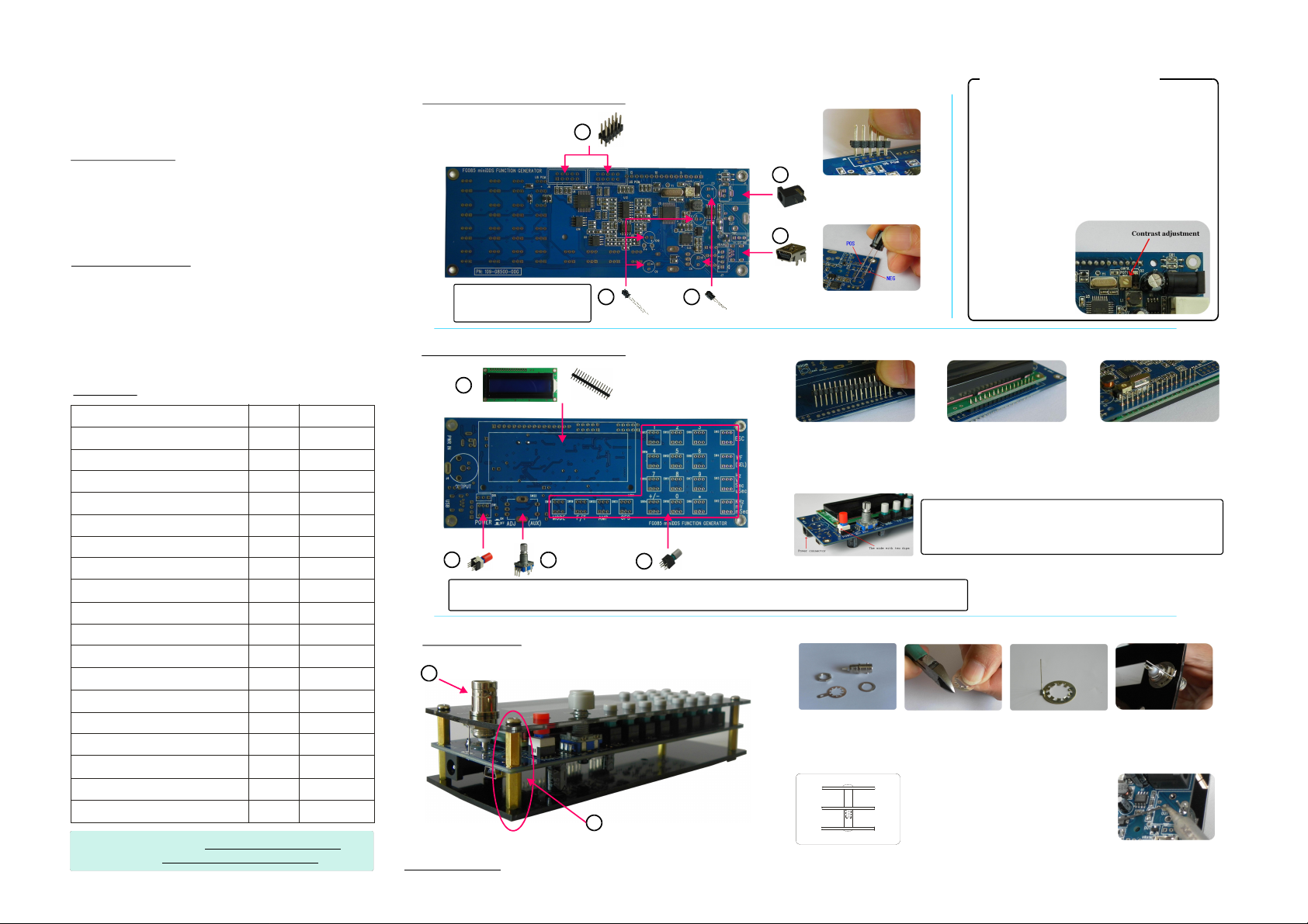
Panel&Connectors
Frequency
Cursor
Amplitude
Output
connector
PowerON/OFF
Incremental
adjustment
(pushforsetting
change)
orperiod
Select
Mode
Output
connector
Select
parameter
DCoffsetWaveform
Dataentry
Correction
orexit
Selectwaveform
Selectunit
Operating
1.ConstantWaveform(CW)Mode
Function Operations
SetFrequency
orPeriod
SetAmplitude
SetOffset
Incremental
Adjustment
SelectWaveform
2.ServoPositionMode
Function Operations
SetPulseWidth
SetAmplitude
Incremental
Adjustment
ChangeSettings
3.ServoRunMode
Use[WF]keytostartandholdservorunning.
[F/T]+[DataEntryKeys*]+[UnitKey]
[AMP]+[DataEntryKeys*]+[UnitKey]
[OFS]+[DataEntryKeys*]+[UnitKey]
Selectparameterandturn[ADJ]dial
Press[WF]key
*Note:Use[ESC]tocorrectorcancelinput
[F/T]+[DataEntryKeys*]+[UnitKey]
[AMP]+[DataEntryKeys*]+[UnitKey]
Selectparameterandturn[ADJ]dial
Push[ADJ](refertodetailedmanual)
*Note:Use[ESC]tocorrectorcancelinput
Powerconnector
()centralpolepositive
USBconnector
Headers&Adjustment
U6
program
U5
program
LCDcontrast
adjustment
Alternative
USBconnector
4.ModeSelection
[MODE]+{Turn[ADJ]toselect}+[WF]
Specification
Ø
Frequencyrange:0-200KHz(Sine)
Ø
Frequencyresolution:1Hz
Ø
Frequencyaccuracy:100ppm
Ø
Periodresolutions:1ms
Ø
Amplituderange:010Vpeak-to-peak
Ø
D.C.offsetrange:-5V+5V
Ø
Waveformmemorylength:256bytes
Ø
Samplerate:2.5Msps
Ø
Outputimpedance:50ohm
Ø
Powersupplyvoltage:15VDC+/-10%
Ø
Currentconsumption:<150mA(withoutloading)
Pleasevisitfordetailedmanualandrelateddocumentswww.jyetech.com
FG085FunctionGenerator
AssemblyGuide
ApplicableModel:08503K
Toolsrequired
1.
Solderingiron(20-25W)
2.
Thinraisin-coresolderofideally0.8mmdiameter
Diagonalflushcutter
3.
Screwdriver4.
ImportantNotes
1.
Followthenumberedordertoinstall.
Onlyinstallpartsgiveninthepartlist.
2.
Payspecialattentiontopolarityandorientation
3.
forelectrolyticcapacitors,headers,switches,and
connectors(seedetailedphotos).
A.InstallComponentsatBack
5
ImportantNote:
Cutleft-overleadsflushafter
solderingforallE-caps
2 3
B.InstallComponentsatFront
100uF
16V
470uF
25V
Poweringupthefirsttime
1.
5
Checkandmakesurepartpolarityand
solderingarecorrectandgood.
2.
Connect15VDCpowersupply(current
capacity>200mA)toJ1.PushSW1to
turntheuniton.
3.
4
1
Shortendsgointo
PCB
2,3
YoushouldseeLCDbacklightup.
Thescreenmayappearblankdueto
incorrectcontrastsetting.Youneedto
adjustthetrimmerPOT1(seephoto)
forcorrect
contrast.
4.
Usekeypad
totestvarious
functions.
Pos(thelonger)lead
goesintosq.pad
6a 6b 6c
PartList
Descriptions
Connector,USBmini-B
E-cap,100uF/16V
E-cap,470uF/25V
Connector,DC005,2mmcore
Header,5X2,2.54mm
Header,16X1,2.54mm
LCD,1602A,white-in-blue
Pushbutton,lockable
Pushbutton,non-lockable
Rotaryencoder,w/pushbutton
BNCconnector,panelmount
Metallead
Knobcap
Panels,frontandback
Standoff,M3x12
Standoff,M3x12+6
Screw,M3x5
PCB,SMDpre-soldered
TechSupport:
Forum: http://forum.jyetech.com
Email:support@jyetech.com
Qty
1
3
2
1
2
1
1
1
20
1
1
1
1
1each
4
4
8
1
Ref.
J10
C5,C9,C10
C3,C4
J1
J6,J8
LCD1
SW1
SW2-21
SW22
J4
6
7
ImportantNote:
C.MountPanels
10
CopyrightJYETechLtd.2011
www.jyetech.com
LongendsgointoPCB PlaceLCDandsolder
7,8
!!!IMPORTANTNOTE:
Forallthepush-buttons,thesidewithtwodipsmust
facetheendwherepowerconnectorlocates.
9
Dothefirsttimepower-upcheckafterfinishingcomponentsatfrontside.Pleaseseeinstructionsattop-right
connerofthissheet.IfeverythinggoesnormalproceedtostepCbelowforinstallationofpanels
8
10a 10b 10c 10d
BNCconnector
Cutwingoffspring
washer
11
Front
11
DN085-06v01
Standoffmounting
(4places)
Back
shortendsattop
Soldermetallead
andbendtoshape
Turnoverandsolder
longendsatback
Mounttopanel
withleadatedge
10e
Installpanelsand
solderupatback
 Loading...