

Page 1

WM-5000P5+ (GPS+RFID)
Guard Tour System
Specification
Page 2

- 2 -
Contents
2. Safety Cautions..............................................................- 5 -
3 Product Overview...........................................................- 6 -
3.1 Packaging ................................................................- 6 -
3.2 Appearance and Structure..................................- 6 -
3.3 Press Key Instruction...........................................- 7 -
3.4 Charging...................................................................- 8 -
3.5 SIM card installation..............................................- 9 -
4 Operational Flowchart.................................................- 10 -
5 Basic Function ...............................................................- 11 -
5.1 Product Profile......................................................- 11 -
5.2 Function Instruction............................................- 11 -
6 Basic settings................................................................- 15 -
7 Site Collection ...............................................................- 17 -
7.1 Site Collection Setup ..........................................- 17 -
7.2 Site collection .......................................................- 17 -
8 Patrol................................................................................ - 19 -
8.1 Patrol setup ...........................................................- 19 -
8.2 Patrol.......................................................................- 19 -
9 Data Sending.................................................................. - 22 -
10 Status Alert...................................................................- 24 -
11. After-sale Services....................................................- 26 -
Page 3

- 3 -
AnnexⅠ Product and Accessories Introduction . - 28 -
1. Reader.......................................................................- 28 -
2. USB Communication cable .................................- 28 -
3. RFID Tag (sold separately) ..................................- 29 -
4. Charger .....................................................................- 30 -
Ø
Page 4

- 4 -
1 Please read before use.
Ø Before using the device, please read all safety cautions and instruction to
guarantee your safe correct use of our intelligent guard tour system.
Ø This instruction is made on the basis of our guard tour system’s defaulted
setup.
Ø The pictures and screen shots which used in this instruction might a little
different from actual product’s appearance.
Ø The content of this instruction might be a little different from actual product,
or might be different from the software which service provider actually
offer .The content is subject to change without any notice. Please visit
www.jwm-rfid.com.cn to get updated version of instruction.
Ø Functions and additional services might be different according to device,
software or service provider.
Copy Right © Shenyang JWM Hi-Tech Development Co.,Ltd 2012. All Rights Reserved.
Shenyang JWM High-Tech Development Co., Ltd. written consent, any unit or individual
will be allowed to extract and copy part of the contents of this instruction or transmitted in
any form.
The product described in this instruction may contain Shenyang JWM Hi-Tech
Development Co., Ltd and its licensee copyrighted software which may exist. Except with
the permission of the rights holders, a person is not allowed to copy, distribute, modify,
excerpt, decompile, disassemble, decrypt, reverse engineer, lease, assign, sub-license
the aforementioned software in any form and other violations of software copyright acts.
But such restrictions unless prohibited by applicable law.
Page 5

- 5 -
2. Safety Cautions
To protect you and others from harm or to protect your device from damage,
please read carefully the information below before use.
Ø Do not use a damaged power cord or plug or a loose power outlet.
Ø Do not touch the power cord with wet hands, or unplug charger by pulling wire.
Ø Avoid charger short circuit.
Ø Do not use the charger which is not approved by the manufacturer to charge device’s
battery.
Ø Always operate device in accordance with the regulations, instructions and signs in
potentially explosive environment.
Ø Do not use device near flammable materials, chemicals places or explosive region.
Shenyang JWM Hi-Tech Development Co.,Ltd
Address:No.22 Shiji Road, Hunnan National Hi-Tech Industrial Zone,
Shenyang city, China
Tel: 0086 24 31681066/31681067/31681068/31681069
Fax: 0086 24 31681065
Email: [email protected]
Website: www.jwm-rfid.com.cn
Page 6
- 6 -
3 Product Overview
3.1 Packaging
a standard package should have items as below:
Ø 1 piece WM-5000P5+ reader
Ø 1 piece of USB communication cable
Ø 1 piece of charger
Ø 1 piece of hex wrench
Ø 1 piece of holster
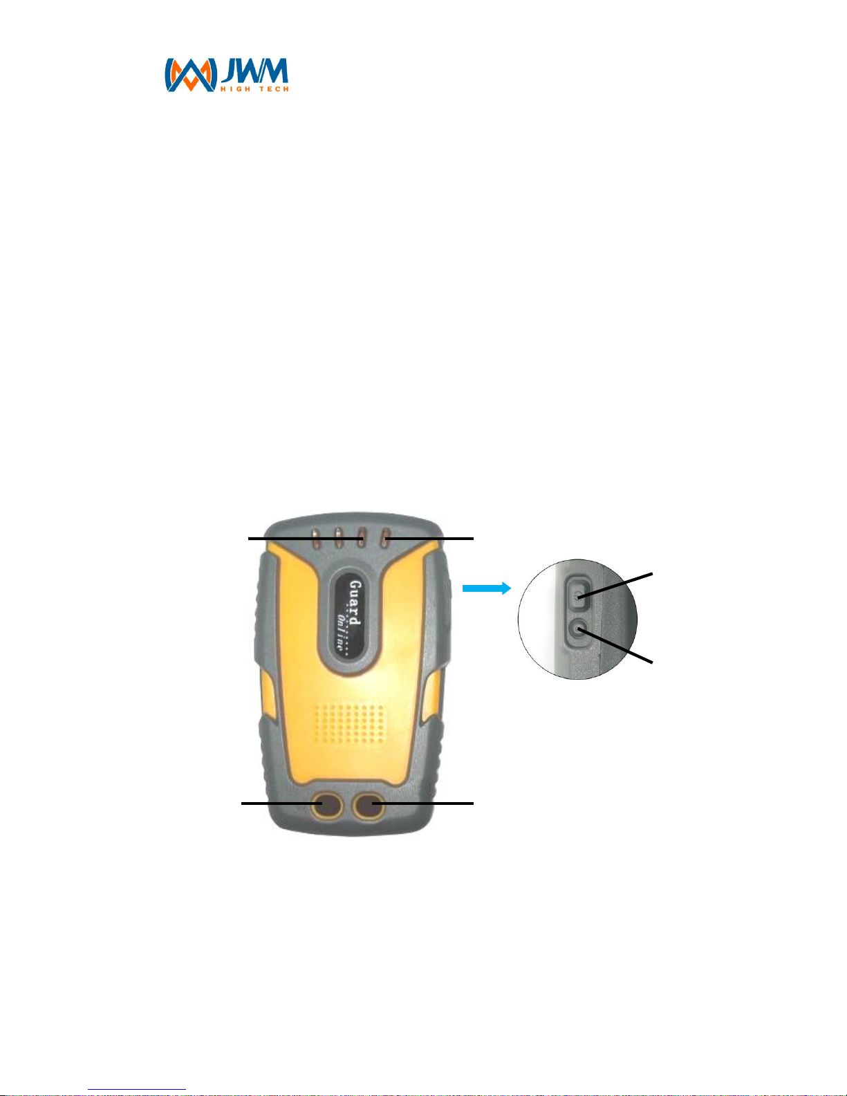
3.2 Appearance and Structure
1、3G LED (green), GPS&RFID LED(red)
2、power LED(blue)
3、”Send” key (Touch)
4、”SOS” key (Touch)
5、On/Off Key
1
3
2
4
5
6
Page 7
- 7 -
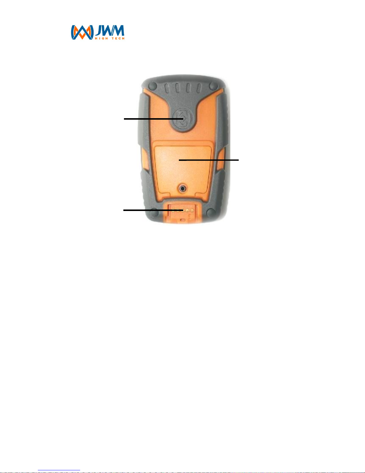
6、Reset Key
7、RFID tag reading area
8、Open and insert SIM card
9、USB port for communication and charging.
3.3 Press Key Instruction
Power on/off key:
Ø Power on: Press On/Off key for 1 second, Power light starts flash, after 1
second, device vibrates once(vibrates twice in collection mode),then light
goes out. After starting up, power light will flash once/3seconds.
Ø Power off: Press On/Off key for 2s, and power light will flash. After 2s,
device vibrates once and power light goes out.
Reset Manually: You can press Reset key for 1s when device is dead.
7
8
9
Page 8

- 8 -
“Send” Key:
Ø “Send” key: Time interval for touching “Send” key is 1s~9s, and device
defaults as 2s.
Ø In collection mode, touch “Send”key for 2 seconds, device will vibrates
once and start to collect GPS site.
Ø In patrolling mode,touch “send”key for 2 seconds, device will vibrates once
and start to send patrol data.
“SOS” key:
Ø Time interval for touching “SOS” key is 1s~9s, and device is defaulted as
4s.
Ø In patrolling mode, touch “SOS”key for 4 seconds, device will vibrates
once and start to send manual alarm data.
3.4 Charging
In Charging: Power LED flash once per 1 second
Charging Completed: Power LED is still on.
Notice
Ø Device charging only match with 4.2V charger.
Ø Please charge device at least 3 hours for first charging.
Ø If the device is put away for a long time (over three months) , please put it
in a dry, cool place.
Ø If the device is not in use for a long time or the battery runs out, you may
not be able to boot up normally, this is a normal phenomenon, please
charge the battery for some time, and then try again.
Ø Battery’s charging time varies with the temperature condition and the
battery usage condition
Page 9
- 9 -
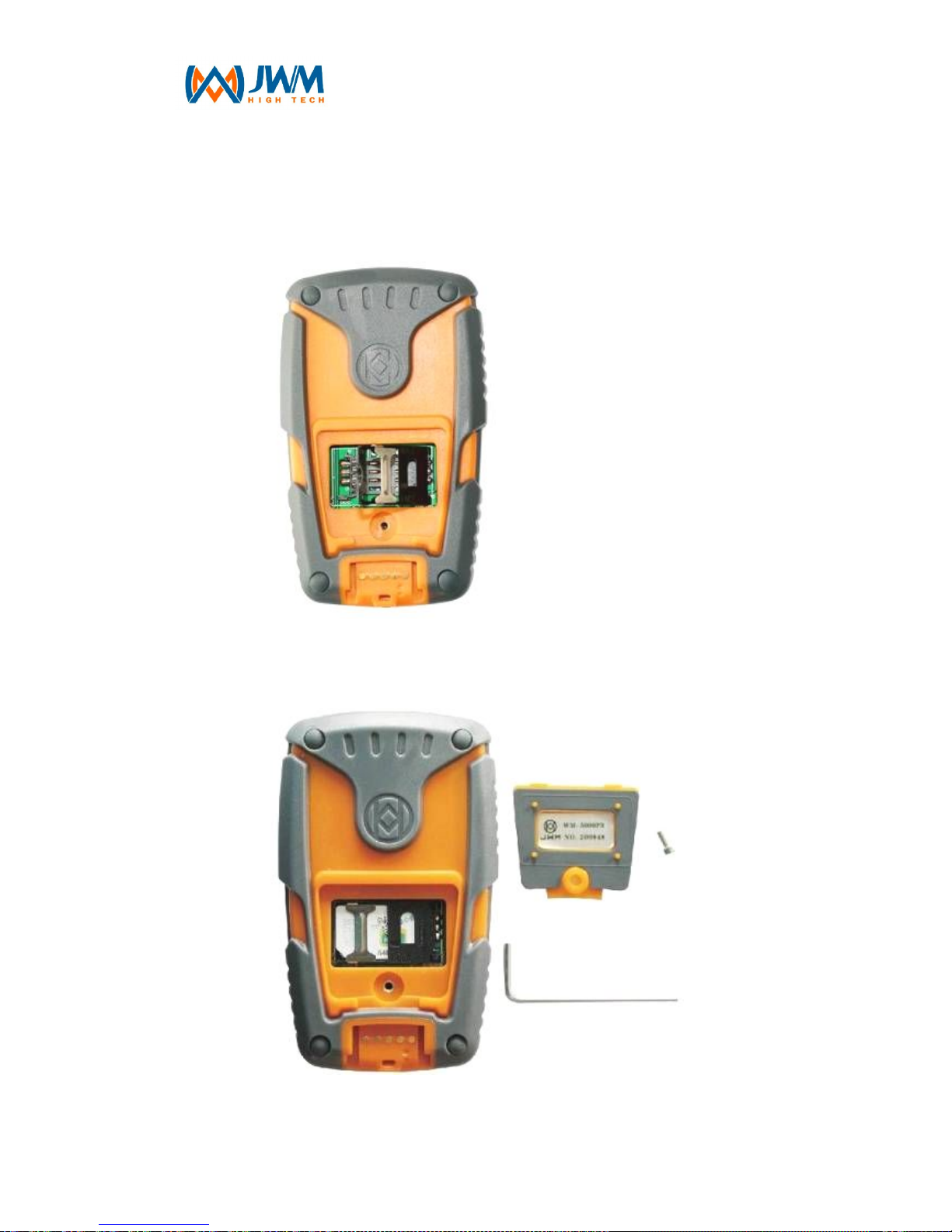
3.5 SIM card installation
Step1: use hex wrench manufacturer provide to open back cover as
picture below.
Step2: insert SIM card to slot,put metallic contact inward and chamfer
side is at bottom left. It should be as the picture below after installation.
Step3: fasten the SIM card slot, and screw on back cover.
Page 10
- 10 -
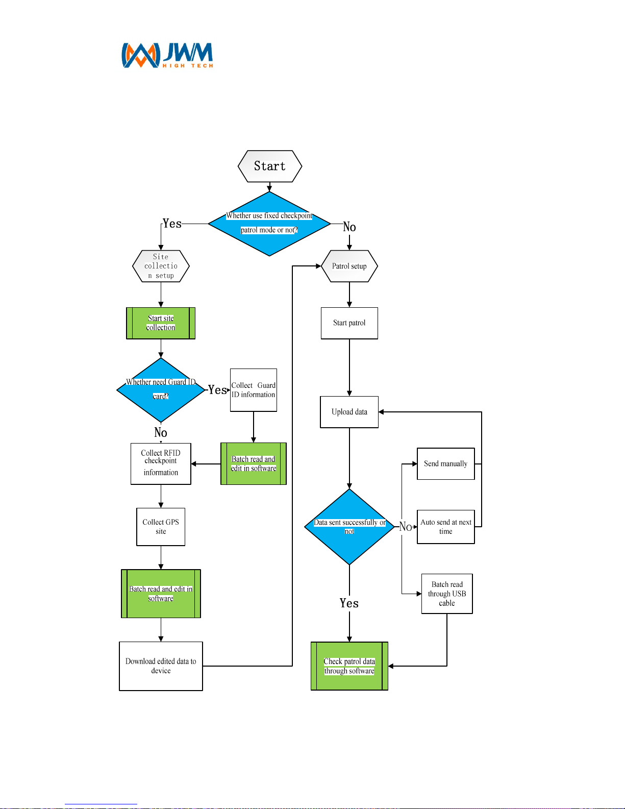
4 Operational Flowchart
Page 11

- 11 -
5 Basic Function
5.1 Product Profile
WM-5000P5+ intelligent guard tour system adopts world-leading
GPS(Global Positioning System) and RFID technologies. Sending patrol
information(guards, longitude&latitude, and RFID tag’s site, event, time)
through 3G network real-time, It can be used to monitor and supervise the
guard who need to take long-distance patrol in many fields. The device will
record guard’s patrol route in real-time, and replay in software’s Google map.
Thus can realize effective management for guard’s working condition and field
work. WM-5000P5+ has two touch keys, one ON/OFF key, and one Reset key.
The device adopts ABS plastic, which can realize totally waterproof,
shatterproof and shockproof. The battery of device is with large capacity,
which guarantee long working hours. The outstanding feature of WM-5000P5+
guard tour system is that sending patrol message or alarm message in real
time.
5.2 Function Instruction
1. GPS Positioning
GPS(Global Positioning System)is a space-based satellite navigation
system which is comprised of 24 satellites. It can provides highly accurate
location, speed and time of most places on earth(98%). WM-5000P5+ adopts
GPS positioning technology, which is widely used for large-area and
long-distance patrol, which can realizing global, all-weathered positioning, and
GPS positioning accuracy less than 10m.
2. RFID tag reading
Page 12

- 12 -
RFID(Radio Frequency Identification)is the use of a wireless non-contact
system that uses radio-frequency electromagnetic fields to transfer data from
a tag attached to an object, for the purposes of automatic identification and
tracking.
WM-5000P5+ supports RFID tag reading function, the RFID tag we
produced is small-sized, damage resistent and waterproof. Each RFID tag has
a unique ID number, and it's carrier frequency is 125Khz, tag reading distance
is more than 3.5cm.
3. WCDMA wireless transmission
WCDMA(Wide band Code Division Multiple Access) is one kind of Third
Generation Mobile Communication Technologies (3G), it refers to the cellular
mobile communication technology which support high-speed data
transmission. WCDMA is a use of code division multiple access (CDMA) reuse
method of 3G mobile broadband spread spectrum communication air interface.
WM-5000P5+ guard tour system supports 3G wireless transmission, sending
guard’s actual patrol condition to control center in real time, with the
outstanding advantages of low price cost, high-speed transmission and safety
data transmission, etc...
4. USB communication
WM-5000P5+ supports USB communication, which adopts unique Pogo
Pin Connector. USB communication can realize device initialization and
records upload.
5. Two working mode
Ø Site Collection mode: it is used for collecting RFID tags and GPS sites.
Ø Patrolling mode: for details, please find point 6.
6. Three patrolling mode
Ø GPS Tracking patrol: If you want to monitor where the guard is right now,
you can use this function. WM-5000P5+ supports GPS tracking patrol,
device will collect GPS positioning data at certain time interval which set in
Page 13

- 13 -
advance, control center displays guard's patrol route and guard’s current
location etc... in real time.
Ø Fixed checkpoint patrol:If the checkpoint is important and need guard to
spend time to make a detailed check, you can use this function.
WM-5000P5+ adopts GPS+RFID mixed patrolling, you can use GPS
function at places where are not very convenient to install RFID tag, and
use RFID tag reading function at places where there is no GPS signal(eg.
inside the building).
Ø Fixed checkpoint patrol + GPS Tracking Patrol:During patrol, guard
can use those two patrol modes at same time, it’s according to customer’s
actual patrol condition and requirements.
7. Two data sending mode
Ø Data sending manually: In this mode, patrol record will be saved in
device, and you need to press “Send” key to send data to control room.
Ø Data sending automatically: In this mode, device will connect 3G
network and send patrol messages automatically as soon as collects
tracking data or reaches GPS fixed checkpoint or reads a RFID tag.
8. Two degrees low-power alarm
WM-5000P5+ supports real-time power capacity alert function. In order to
avoid affecting guard’s normal patrol work, device should be charged when it
is in 1-degree low-power alarm condition.
9. Guard(optional)
If guard need to scan Guard ID tag during patrol, then guard ID tag should
be downloaded to device in advance. Before patrol started, guard need to
scan his own Guard ID tag in advance. When uploading patrol records, it
indicates guard's name.
10. Real-time monitoring function
Control center can check guard's location and working condition in real
time on software's Google Map.
Page 14

- 14 -
11. Alarm Manually
“SOS” key is specially designed for guard who need to patrol alone or
patrol at remote areas. Guard can press “SOS” key to send alarm message to
control center for help anytime and anywhere.
12. Records Storage Capacity
Ø Patrol records: device can store 60000 records at most.
Ø Unknown sites:device can collect 1500 unknown sites at most.
Ø RFID Guard ID tag:device can download 3000 guard’s name at most.
(optional)
Ø RFID checkpoint: device can download 5000 RFID checkpoints at most.
Ø GPS site: device can download 500 GPS sites at most.
Page 15

- 15 -
6 Basic settings
Device number
It consists of 6 digits, which is used to identify the
device.
Device initialization
It is used to clear all data in the device, such as guard
names, GPS locations, RFID check points, and
collection data.
Device data
clearance
It is used to clear up all patrol data (patrol data, alarm
data)
Server IP address
setup the server fixed IP address into the device
Domain name, DNS
If there is no fixed IP address in the server, the
parameters should be set up; the domain address and
DNS should be set up into the device; the device will
send data to the server through the domain address
APN, user
name,
password
APN and identification information, which is confirmed
by the SIM card; the specific parameters can be got
from SIM supplier.
PIN
User name setup (consists of 4 digits); it is used to
identify the user name
working mode
Collection mode and patrol mode
patrol mode
Fixed check point mode, track mode, and Fixed check
point mode track mode
data sending mode
Auto mode and manual mode
Positioning time
interval
Under the track mode, set up the frequency to send
GPS data
sending button
setup
Under the collection mode, setup the time for pressing
the button to collect the check points and send data
Page 16

- 16 -
(under the patrol mode)
Alarm button
settings
Under the patrol mode, setup the time for pressing the
button to send alarm data
Page 17

- 17 -
7 Site Collection
7.1 Site Collection Setup
Taking stand-alone version software as example
Install patrol management software on control center’s server at first, for
details, please take software instruction for reference. After installation,
connect device with server by USB cable, and do setups as below:
Ø Device ID number setup: 6 digits at most
Ø Device initialization
Ø Delete device previous data
Ø Working mode setup: set device to collection mode
7.2 Site collection
Before site collection, please make sure device has been set to
collection mode. In collection mode, device will vibrates twice when
turned on.
Ø Collect GPS site:Turn on device, after positioning, GPS&RFID LED flash
once/1s, press “Send” key for 2s, device start collection with one vibration.
After collection, GPS&RFID LED continues flash 5times with 2 vibrations
to save collection data. It will need 30 seconds to collect a site; device will
vibrates 3 times if collect failed.
Ø Collect RFID tag:Close RFID tag to device’s tag reading area, device will
save record by vibrating twice along with GPS LED flash 5 times.
Ø After collection, connect device with server by USB cable again, batch
upload collect data to software and edit those data. For details, please
Page 18

- 18 -
take software instruction for reference.
Ø Device can collect 1500 unknown sites at most(GPS site and RFID
checkpoint), when records are full, device will vibrate 3 times when collect
new site, and this data will not be saved.
Page 19

- 19 -
8 Patrol
8.1 Patrol setup
Taking stand-alone version software as example
connect device with server by USB cable, and do patrol setups as below:
for details, please take software instruction for reference.
Ø Server’s IP address or domain name, DNS setup.
Ø APN(user’s name, password)
Ø PIN
Ø working mode
Ø patrol mode
Ø data sending mode
Ø time interval for positioning
Ø “Send”key setup
Ø “SOS”key setup
Ø download guard ID tags and sites to device
8.2 Patrol
Please make sure you have already finished the patrol setup.
1. fixed checkpoint patrol mode:
Ø For device which download guard ID tag , you need to read Guard ID card
before patrol. Device vibrates once along with GPS&RFID LED continues
light 1second.
Ø During patrol, device will vibrates once along with GPS&RFID LED flash 5
times when guard arrives GPS fixed checkpoint.
Ø During patrol, device will vibrates once along with GPS&RFID LED flash
Page 20

- 20 -
twice after reading RFID tag.
Sending patrol records manually: In this mode, data will be saved in
device, and only be sent when guard press “Send” key to connect with
3G network
Send patrol records automatically. In this mode, after guard arrives
GPS fixed checkpoint or read a RFID tag, device will connect with 3G
network and send data automatically
2. tracking patrol mode:
Ø For device which download RFID guard ID tag , you need to read Guard
ID card before patrol. Device vibrates once along with GPS&RFID LED
continues light 1second.
Ø After positioning, device will collect and save GPS site at setted time
interval
Sending patrol records manually: In this mode, data will be saved in
device, and only be sent when guard press “Send” key to connect with
3G network
Send patrol records automatically: In this mode, device will connect
with 3G network and send data automatically when there is tracking
records.
3. Fixed checkpoint patrol +Tracking Patrol:
Ø For device which download RFID guard ID tag , you need to read Guard
ID card before patrol. Device vibrates once along with GPS&RFID LED
continues light 1second
Ø During patrol, device will vibrates once along with GPS&RFID LED flash 5
times when arriving GPS fixed checkpoint
Ø During patrol, device will vibrates once along with GPS&RFID LED flash 1
second after reading RFID tag.
Ø During patrol, device will collect and save device will collect and save GPS
site at setted time interval.
Page 21

- 21 -
Sending patrol records manually. In this mode, data will be saved in
device, and only be sent when guard press “Send” key to connect with
3G network
Send patrol records automatically. In this mode, device will connect
with 3G network and send data automatically when there is tracking
records.
4. Alarm Manually: Guard can press “SOS” key anytime to send alarm
message during his patrol. Press “Alarm” key for 4s, device vibrates once and
sending alarm message to control room, if failed, it will be saved in device.
5. Power capacity alert:
Ø normal power capacity: When battery voltage higher than 3.8V, power
LED flash once/3s;
Ø 1-degree low-power alarm: When battery voltage lower than 3.8V, power
LED flash twice/3s, and send low-power alarm message to control
center after first GPS positioning.
Ø 2-degree low-power alarm: When battery voltage lower than 3.6V,
device will shut down automatically.
6. Records Storage:
Ø Data storage is coming to maximum capacity : when data reaches
55000pcs, device will vibrates 5 times when save data again.
Ø Data storage is full: when data reaches 60000pcs, data will not be saved,
and device will vibrates 6 times per 5 seconds.
Page 22

- 22 -
9 Data Sending
1. Send data manually:
In manual mode, data will be saved in device, press “Send” key to send
data, device vibrates once and 3G LED is still on, start to send data.
Ø Sending data successfully, device vibrates once, 3G LED will be off after it
flashes 5 times.
Ø Sending data failed, device vibrates 3 times, 3G LED is off.
2. Sending data automatically:
Ø Sending GPS track data, 3G LED is still on, sending successfully, 3G LED
will be off after it flashes 5 times. Sending failed, 3G LED will be off.
Ø Sending fixed checkpoint data, 3G LED is still on, sending successfully,
device vibrates once, 3G LED will be off after it flashes 5 times. Sending
failed, device vibrates 3 times, 3G LED is off.
3. Sending backup data:
Ø Automatically: before device sends patrol data, device need check
whether it has backup data, if so, the backup data will be sent according to
time order.
Ø Manually: during patrol time, press “sending key”, device will send data.
Ø Reading data through USB: reading backup data through USB cable.
4. Sending Panic alarm data:
After pressing Panic alarm key, 3G LED is on, start to send panic alarm
data.
Ø Sending successfully, device vibrates once, 3G LED will be off after it
flashes 5 times.
Ø Sending failed, device vibrates 3 times, 3G LED is off.
5. Sending low power alarm data:
When the device has low power, 3G LED is on, start to send low power
Page 23

- 23 -
alarm data.
Ø Sending successfully, device vibrates once, 3G LED is off after it flashes 5
times.
Ø Sending failed, device vibrates 3 times, 3G LED is off.
Notice: device is under low power status, device will send low power
alarm data when it is turned on.
Page 24

- 24 -
10 Status Alert
Status Alert
power on under collection
mode
blue led long light,2 vibrations
power on under patrol
mode
blue led long light,2 vibrations
power off blue led long light, vibrates every second
standby blue led lights every second
low power blue led flashes twice every 3 seconds
charging blue led lights once every one second
pull charge blue led long light
start registration green led lights once every second
registration ok green led lights out, 1 vibration
Registration failed green led lights out, 3 vibrations
Sending data green led long light
Auto sending data ok
green led flashes 5 times and 1 vibrations(
no
vibration under GPS tracking mode)
manual data sending ok green led flashes 5 times and 1 vibration
auto data sending failed
green led lights out,3 vibrations(no vibrations
under GPS tracking mode)
manual data sending
failed
green led lights off and 3 vibrations
GPS location red led flashes once every seconds
data storage wrong 4 vibrations
Time clock wrong 3 vibrations
GPS collection ok red led flashes 5 times and 2 vibrations
GPS collection failed 3 vibrations
RFID collection ok red led flashes 5 times and 2 vibrations
Collection data is full 3 vibrations
RFID tag reading red led light on 1 seconds and 1 vibration
read unknown RFID tag red led light on for 2 seconds and 2 vibrations
Page 25

- 25 -
Arrive in GPS location red led flashes 5 times and 1 vibration
Data storage is coming to
maximum capacity
5 vibrations
Data storage is full vibrates 6 times every 5 seconds
Page 26

- 26 -
11. After-sale Services
When we handed this qualified excellent system to you, in fact our service
has just started. We will provide you with excellent training administrator,
technical service at any time, in order to make sure you have operated the
system properly. Even if the world’s top products can’t guarantee their
products without problems all the time, but we could guarantee that the
products you bought are with real quality warranty and maintenance, once
there is any problems occurs, we provide timely maintenance. Our sales
people will accompany you until the problems has been solved. We setup
service files for each single customer, the design, installation, usage, and
maintenance will get the complete data in order to provide you accurate,
timely and thoughtful after sale services.
Service response time≤24 hours
We implement the lifelong maintenance to the user, responsible for the
free software upgrades and technical consolation, and at the same time puts
forward the quality assurance period whether product is caused by human, so
long as the users are put forward to repair, goods within 24 hours of rapid
return to ensure the normal use. And then negotiate processing opinion, let the
user 100% trust and 100% satisfied.
Guarantee clause
·Any legal buy inside china, problem caused by quality, will enjoy company
service,
·Any products enjoy one year warranty since the purchase day.
·Any case belongs to below circumstances, will not enjoy free maintenance.
Maintenance center will charge.
Page 27

- 27 -
Ø Due to the user or the third part’s negligence, abuse, misuse, malicious
damage or damage caused by evil.
Ø User dismantle the device without approval from JWM( any incorrect
change that may cause damage)
Ø Connection to inappropriate accessory, use without working manual,
product’s damage caused by transport and other accident.
Ø Products failure or damage caused by incorrect or inappropriate use.
Ø All labels for products appearance, all parts, consumable parts and nature
wear and tear for products appearance caused by long-time use
· Please leave correct name and telephone information, so that maintenance
center could get in touch with you in time, if information are not clear,
maintenance center will not process.
·For all above, if there are discrepancies with the national policy, please
subject to national policy.
Page 28
- 28 -
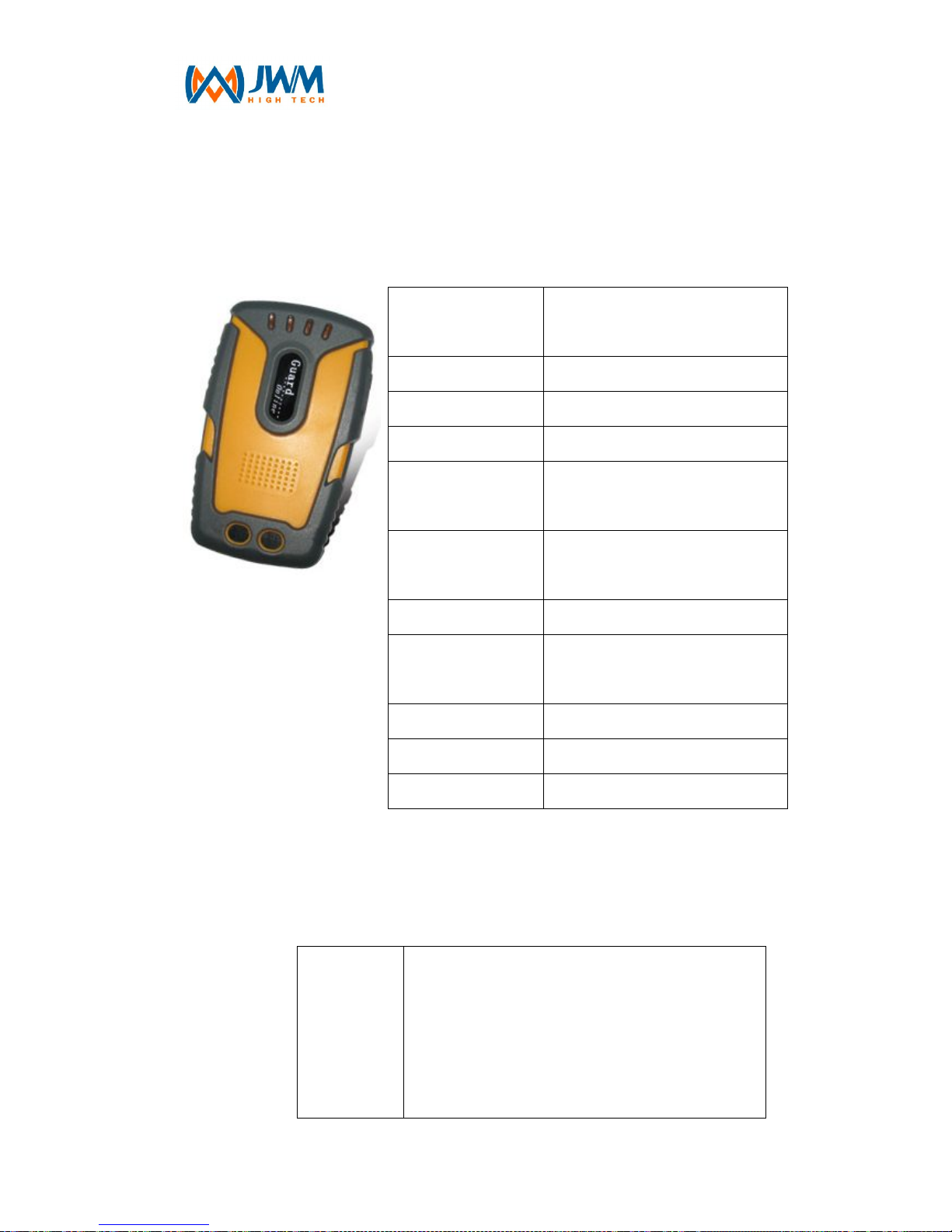
Annex Ⅰ Product and Accessories Introduction
1. Reader
GPS Positioning
Precision
≤10 meters
Cold boot ≤33s
Hot boot ≤1s
Reading range ≥3.5cm
Battery
2000mAh/3.7v polymer
lithium battery
Working time (for
one full charge)
30 hours
(sending data every 70S)
communication USB/GSM/3G
Working
temperature
-40℃~+85℃
Relative humidity
25%~85%
Dimensions 102mm*63mm*26mm
Weight 147g
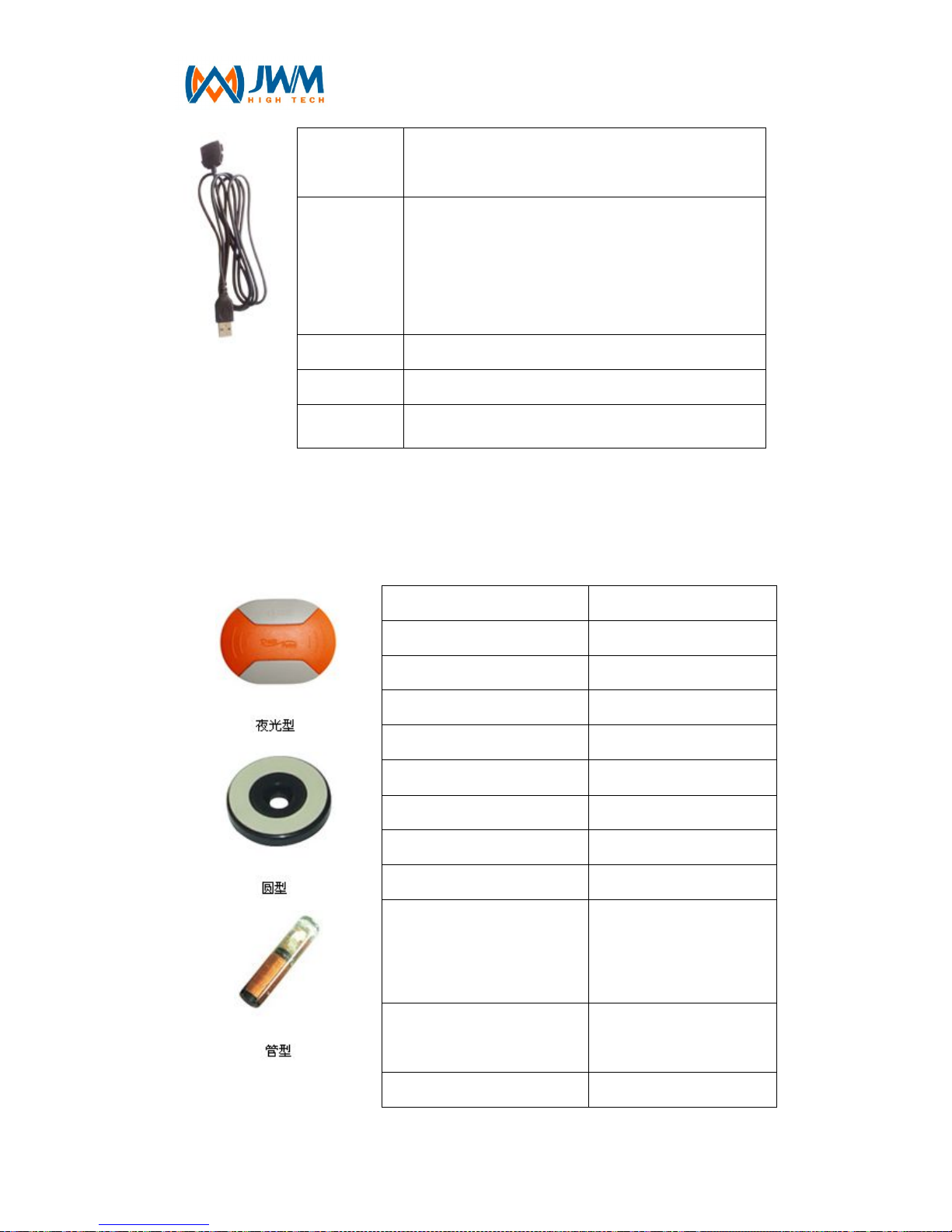
2. USB Communication cable
Structure
special mould structure, made of high
phosphorus copper conductor, inner layer
has four pcs bare copper wires, outer layer is
made of high density polyethylene and
colorful coded insulators.
Page 29
- 29 -
Standard
YD/T1019 , IEC61156 , ANSI/EIA/TIA-568
three cable standards
Features
Low transferring return loss; continuous
insulation consistency; anti electromagnetic
interference which makes a lower rate of
transferring mistake
Delay 5.02 ns/m
Impedance
107–11Ohm
Return loss
26.0dB
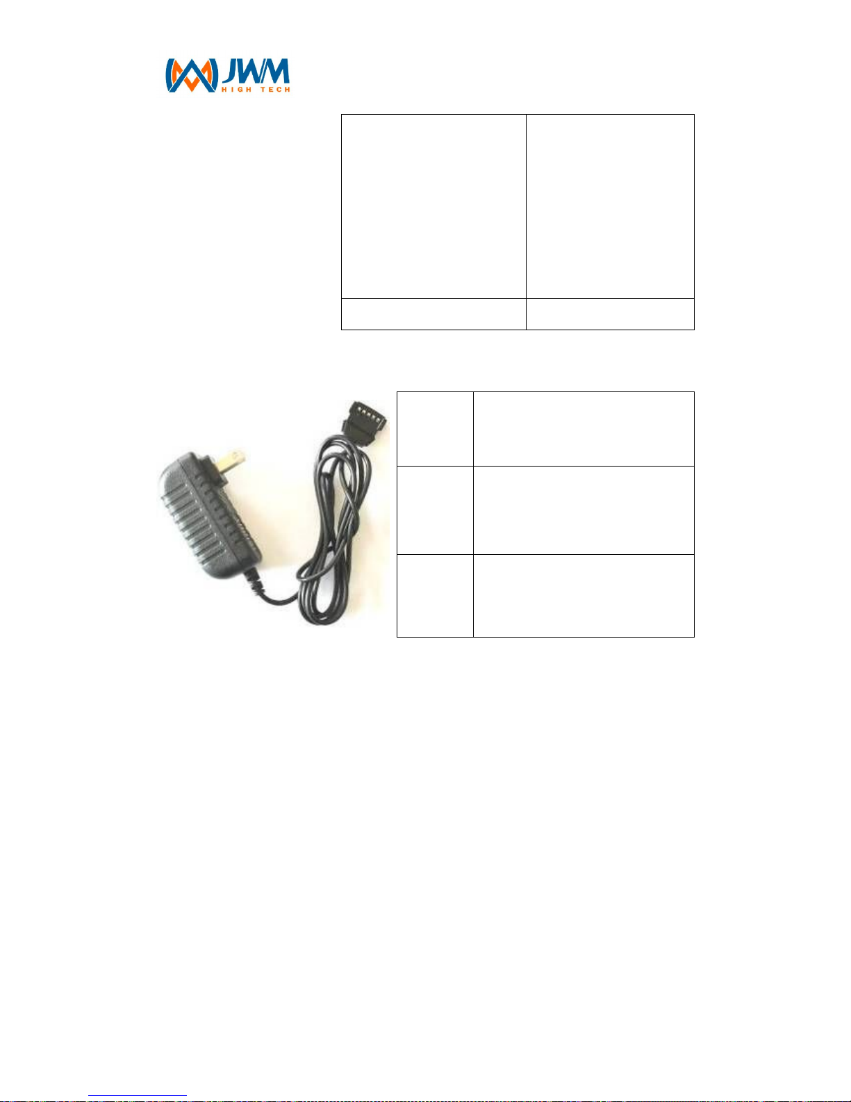
3. RFID Tag (sold separately)
Function Read only
Memory 64bit
Chip model number RFID H4001
Working frequency 125kHz
Code mode Manchester encoding
Power None
Reading range ≥3.5cm
Working temperature -40 ℃ ~ +85℃
Waterproof or no yes
Electromagnetic
compatibility(RFIDC)
Immune to
electromagnetic
interference or X-ray
Signal penetration
Can through
non-metallic materials
Package materials ABS plastic
Page 30
- 30 -
Dimensions
Luminous tag:
76mm×56mm
round shape tag:
Ф30mm×4.5mm
nail shape tag:
Ф6.5mm×28mm
Weight About 2g
4. Charger
Input
voltage
AC 100V-250V 50-60 Hz
Output
voltage
DC 4.2V
Output
current
1000mA
Page 31

- 31 -
FCC RF Exposure Information and Statement
The SAR limit of USA (FCC) is 1.6 W/kg averaged over one gram of tissue. Device types A208
(FCC ID: RRB-WM-5000GT) has also been tested against this SAR limit. The highest SAR value
reported under this standard during product certification for use is 0.204W/kg. This device was
tested for typical body-worn operations with the back of the handset kept 1.0cm from the body.
To maintain compliance with FCC RF exposure requirements, use accessories that maintain a
1.0cm separation distance between the user's body and the back of the handset. The use of belt
clips, holsters and similar accessories should not contain metallic components in its assembly.
The use of accessories that do not satisfy these requirements may not comply with FCC RF
exposure requirements, and should be avoided.
FCC WARNING
This device complies with Part 15 of the FCC Rules. Operation is
subject to the following two conditions:
(1) this device may not cause harmful interference, and
(2) this device must accept any interference received, including interference that may cause
undesired operation.
NOTE 1: This equipment has been tested and found to comply with the limits for a Class B digital
device, pursuant to part 15 of the FCC Rules. These limits are designed to provide reasonable
protection against harmful interference in a residential installation. This equipment generates,
uses
and can radiate radio frequency energy and, if not installed and used in accordance with the
instructions, may cause harmful interference to radio communications. However, there is no
guarantee that interference will not occur in a particular installation. If this equipment does cause
harmful interference to radio or television reception, which can be determined by turning the
equipment off and on, the user is encouraged to try to correct the interference by one or more of
the following measures:
- Reorient or relocate the receiving antenna.
- Increase the separation between the equipment and receiver.
-Connect the equipment into an outlet on a circuit different from that to which the receiver is
connected.
-Consult the dealer or an experienced radio/TV technician for help.
NOTE 2: Any changes or modifications to this unit not expressly approved by the party
responsible for compliance could void the user's authority to operate the equipment.
 Loading...