


SCAN-650
Scanning Sonar
OPERATION MANUAL
JW FISHERS MFG INC
rev 811
JW FISHERS MFG INC
1953 COUNTY ST.
E. TAUNTON, MA 02718 USA
(508) 822-7330; (800) 822-4744; FAX (508) 880-8949
Email: jwfishers@aol.com WEB: www.jwfishers.com
1

SCAN-650
Scanning Sonar
OPERATION
AND
MAINTENANCE
MANUAL
Surface Sonar Processor Included
(508) 822-7330; (800) 822-4744; FAX (508) 880-8949
Email: jwfishers@aol.com WEB: www.jwfishers.com
2
JW FISHERS MFG INC
1953 COUNTY ST.
E. TAUNTON, MA 02718 USA

TABLE OF CONTENTS
• CAUTIONS............................................................................................................. 4
• SPECIFICATIONS AND OPTIONS........................................................................ 5
• MINIMUM SYSTEM REQUIREMENTS................................................................. 6
• INTRODUCTION.................................................................................................... 7
• SYSTEM COMPONENTS ..................................................................................... 9
• THEORY OF OPERATION .................................................................................. 11
• OPERATOR SWITCHES AND CONTROLS ....................................................... 16
• INSTALLING HARDWARE AND SOFTWARE .................................................... 27
• CABLING THE SYSTEM ..................................................................................... 31
• ATTACHING TO ROV .......................................................................................... 32
• OPERATION ........................................................................................................ 35
• SAMPLE PLAYBACK ........................................................................................... 36
• SAMPLE RECORDING ....................................................................................... 37
• FAQs .................................................................................................................... 39
• TROUBLESHOOTING......................................................................................... 4 1
• APPENDIX A (configuring GPS) .......................................................................... 44
• APPENDIX B (USB to Serial Adaptor) ................................................................. 45
• MAINTENANCE................................................................................................... 47
• WARRANTY......................................................................................................... 47
3

CAUTIONS:
• Do not allow the SCAN-650 to be exposed to excessive heat by leaving it in direct
sunlight or inside of a closed vehicle on a hot day. Excessive heat can buildup
inside the housing which can damage the electronics and/or destroy the waterproof
seals.
• Take special care of the black flexible boot located on the top of the scanning head.
The black flexible boot is an acoustic window that should be keep clean (soap and
water) and protected from damage.
• Do not remove the (6) screws that hold the black flexible boot in place on the scanning head in-place. The scanning head contains a liquid that will drain out if the
screws are loosened.
• Do not remove the black hex head bolt on the scanning head (this is only on the 2
piece SCAN-650).
• When mounting the scanning head, be sure the arrow on top of the scanning head is
pointing forward, this will be the top of the screen on the PC.
4

SPECIFICATIONS
PERFORMANCE/DESCRIPTION:
• Frequency............................................................................................................ 650 kHz.
• Beamwidth - horizontal x vertical .......................................................... 2.4 deg by 40 deg.
• Ranges: ........................................................................................ 5, 10, 20, 40, 60 meters
. .................................................................................................. 16.5, 33, 66,132,198 feet
• Max depth ............................................................................................... 300 m / 1,000 ft .
• Input voltage
- Sonar Processor .......................................................... 9-12 vdc or 120/220 vac (5 watt).
- Scanning Head................................................ from Sonar Processor or 9-36 from ROV.
• Cable ..................................................................................................... 2 or 4 conductor.
DIMENSIONS/WEIGHT:
• Sonar Processor..................................... 8”Wx9"Dx2.5"H ......................... 2 lbs / 0.9 Kg.
650A:
• Scanning Head and housing ................... 3.5"Dia x 10.5"L ................. 3.6 lbs 1.6 Kg (air).
............................. 0 lbs / 0 Kg (water).
650B:
• Scanning Head ......................................... 3.5"Dia x 4"L ................... 1.4 lbs / .6 Kg. (air).
.......... .375 lbs / .17 Kg. (water).
• Housing ..................................................... 3.5”Dia x 9"L ..................... 2.8 lbs 1.2 Kg (air).
..................... 0 lbs / 0 Kg (water).
Note:
If 180° sweep, cut times in half; if 90° sweep, cut times by four, etc.
• up to 600 meters / 2,000 feet of cable
• Carrying case
OPTIONS
5

SCAN-650 MINIMUM SYSTEM REQUIREMENTS
CPU: Intel or AMD. 500MHz
System memory: 64 Mb RAM
(Faster CPU and more RAM will allow faster scanning)
One available USB port
Windows 98 or later
15 Mb of free disk space for program installation
Disk space for file recording:
5 Meter Range
.5 deg step ............... 52 meg/hr ............ 13 hrs/CD, 90 hrs/DVD
2 deg step ................ 30 meg/hr ............ 23 hrs/CD, 200 hrs/DVD
10 Meter Range
.5 deg step ............... 27 meg/hr ............ 25 hrs/CD, 170 hrs/DVD
2 deg step ................ 17 meg/hr ............ 39 hrs/CD, 270 hrs/DVD
60 Meter Range
.5 deg step ............... 14 meg/hr ............ 50 hrs/CD,345 hr/DVD
2 deg step ................ 11.5 meg/hr ......... 60 hr/CD, 400 hr/DVD
Video Card capable of:
16 bit color
Screen Area of 800 x 600 pixels (minimum)
Optional:
CD or DVD burner for archiving files
Note: For the fastest scanning capability, shut down all other programs (including
virus scan).
6

INTRODUCTION
The SCAN-650 is a high performance imaging sonar system available in two different package
configurations which enables it be used on large or small ROVs. It can also be pole-mounted and
used from a small boat in shallow water.
The SCAN-650A configuration is used with
larger ROVs, or when the main application is
boat deploying the unit on a pole (see photo next page).
The black scanning head is connected permanently to
the electronics module. A cable (not shown) comes out
of the bottom of the electronics module and connects
to the Sonar Processor.
The SCAN-650B configuration is used with
smaller ROVs. The black scanning head is mounted
to the front of the ROV and a short cable connects the
head to the electronics module which is mounted on the
side or under the ROV. Cabling options include a hardwired
version where a cable comes out of the bottom of the of the
electronics module and connects directly to the Sonar Processor or a set of short wires equipped with under water connectors and a hull penetrator. This option allows the wiring from
the scanning head to enter the ROV. The scannin head can
draw power from the ROV and utilize (2) spare wires in the ROV
umbilical cable for communication with the Sonar Processor.
The Sonar Processor is located in the boat and
allows fine tuning of the signal from the electronics
module prior to being displayed and recorded on
the PC display. It is used with both of the above
models. The Sonar Processor also includes an
interface for a GPS receiver.
7

Mounting the scanning
3
3
4
4
head on a pole allows
it to be deployed from
a boat in shallow
water .
23
23
SCAN-650
When operating in shallow water, the
scanning head can taped or clamped to
a pole and deployed over the side of a
boat or off a dock. Pole must be held very
steady (and no waves if deployed from a
boat) to insure a clear picture. If the surface conditions are too rough, the scanning head can be attached to a tripod and
lowered to the bottom (2’ off bottom for
small targets) to provide clear images.
There are times when it is advantages to
deploy the scanning head inverted (upside down). This might occur when deploying on a pole. The software allows
inverted scanning (see “Settings” Menu
pg 18 .)
Pole
SCAN-650
2
2
Transducer (black end) is
positioned downward when
operating with a pole. Be
sure transducer is below
bottom of pole (so pole
does not interfere with
signal).
Tripod deployment
The target below is a pickup truck (note large
black shadow) located in 18 feet of water. The
scanning head was mounted on a pole which
was deployed from a small boat (see top photo).
The most common application is mounting the scanning head
on an ROV. The ROV can rest on the bottom or hover just off the
bottom and the sonar scans 360 degrees looking for targets.
SCAN-650 scanning head
mounted on Fishers SeaLion
ROV.
8

SYSTEM COMPONENTS
5
5
Signals from the scanning head travel up the cable to the Sonar Processor on the surface. The
signals are processed and sent to the PC where the signal is displayed and recorded. The boat’s GPS
receiver can also be connected to the Sonar Processor. If connected, the boat’s Latitude and
Longitude will be displayed and recorded by the PC.
Transducer Head and
Electronics
234
234
cable to surface
Sonar
Processor
PC (customer supplied)
USB Port
Boat’s
GPS
The Sonar Processor connect to any available USB port on the PC. (Note: It is best to use the
same physical USB port every time you operate)
The Sonar Processor can be powered by 9 - 12 vdc. A 120/220 vac to 12 vdc wall transformer is
supplied to power the system from a 120/220 ac voltage supply . A cable with battery clips is
supplied to power the sonar from a 12 volt battery .
Wall Transformer
Cable for 12 v battery
9

LEFT
BLANK
10

THEORY OF OPERATION
SONAR BASICS
Sonar is the bouncing of an acoustic signal off a target and then measuring the time it takes to
return - thus giving us distance, and measuring the size or amplitude of the returned signal - thus
giving us hardness of the target. Since the speed of sound in water is known (1500 meters per
second), it is easy to determine the distance to a target by simply measuring the time it takes to
make the round-trip and dividing by two. If we examine the size of the returned signal (amplitude),
we can determine if the sonar signal hit a soft object (mud bottom) or a hard object (rocky bottom).
The muddy bottom will absorb much of the signal with very little signal (echo) being returned. The
rocky bottom produces a large echo which is called a hard return.
The acoustic signal is produced by a transducer. In operation, the transmitter generates an
electrical pulse which is applied to the transducer . The transducer converts this pulse to a mechanical vibration which produces an oscillating pressure wave in the water thus forming a sound pulse.
The pulse then travels away from the transducer until it strikes an object at which point some portion
of the pulse is reflected back to the transducer as an echo.
When the echo returns to the transducer , the transducer is mechanically excited by the sound
pressure and converts the vibration into an electrical signal. This signal is then detected and amplified by the receiver.
The control/display unit regulates the precise timing between the transmitters, receiver and display elements.
DEPTH SOUNDER
Depth sounders are a simple form of sonar. They send out a conical shape energy pulse toward
the bottom, listen for the return, calculate the time it took, and displays the answer in feet (of depth).
If your depth sounder has a display or a printout, a line will be drawn representing the bottom. Because the beam is so wide (15 to 30 deg), the beam will be on the object for a long time as you pass
over it. As a result, even smaller objects appear to be quite large on the printout. Fish show up as
large arcs on the display. Depth sounders typical operate at a frequency of between 50kHz and
200kHz. Good for long range but not for detecting small targets
SCANNING SONAR
Scanning sonar refines the process by decreasing the beam width to a very narrow 2 deg (2 deg
by 40 deg fan shaped beam) and dramatically increasing the frequency of the signal (typically 600kHz
range). The very narrow fan shaped beam and high frequency dramatically improves the detail of the
objects on the bottom. The fact that scanning sonar sweeps the beam back and forth across the
bottom gives a major improvement over the depth sounder printout for bottom detail. Not only can
very small targets be detected but the details of the target can be seen.
Signal
SCAN-650
SCAN-650
Signal
Side View (fan shaped signal)
T op View (very narrow signal)
11

THEORY OF OPERATION (continued)
The JW Fishers SCAN-650 scanning sonar operates by transmitting a short, high energy,
narrow width acoustic wave. This high energy acoustic wave hits directly below the transducer
Fish
Transducer
first (as shown below)
100 m Range Switch
25 meter range
100 m
Target #2
3 meters
10 m
Acoustic Wave
Target #1
As the pulse continues to sweep across the bottom, away from the transducer, echoes
continuously return to the transducer (see below). The returning echos strike the transducer
which produce the return electrical signals.
Fish
Transducer
100 m Range Switch
A look at returning echoes
Hard Return
No Return Echos (Shadow)
#1
3 meters
10m
Returning Echos
Light Return
Medium Return
25 meter range
100 m
Acoustic
Wave
Hard Return
#2
The harder the object (rocks, metal, etc ), the larger the returned echo. The angle of the
bottom surface and target angles also impact the amplitude of the return signal. The left
side of target #1 and #2 will produce a larger (harder) return echo than the top area. When
the acoustic wave hits the top of the target, some of the echo is reflected away from the
fish. When the bottom slopes away and down from the fish, only light echo’s return from the
bottom. When the bottom slopes upward, medium echo returns are received. If a hard
target is positioned on a down or on a up-sloping bottom, a hard return will result from the
target. If a target is up “off the bottom”, as is target #1 and #2, then there will be an area
directly behind the target that will be blocked from the acoustic wave. No echo returns will
be received from that area by the fish. When displaying this area, the display will show a no
signal color . This area on the display is called the target’s “shadow”.
The return electrical signals are amplified by the preamp and sent up the cable to be
processed by the “time variable gain” (TVG) circuit in the Sonar Processor . (Refer to
page 15 for a more details on the TVG circuit.)
12

THEORY OF OPERATION (continued)
After the return signals are processed by the TVG, the Sonar Processor takes evenly spaced
samples of the echo returns which are processed and displayed on the PC screen as a very narrow
sector that changes color along it’s length depending on the intensity of the reflected signal.The
amplitude of the returned echo samples, during one line, determines the color for each point along
the line. The larger the amplitude of the return, the greater the change of color on the display. Every
one pulse out of the transducer fills one “degrees per step” sector.
0 deg
Screen
View
Single line displayed
270 deg
on the screen.
The width of this
sector is determined
by the “Degrees per
Step” setting.
SCAN-650
90 deg
Continuous 360 degree
180 deg
sweep or any portion of
360 degrees.
After the line is displayed, the transducer head (scanning head) rotates (steps) slightly to the right
and the sequence is repeated. The smaller the step (1/2, 1, 1 1/2, or 2 degree) the higher the resolution
of the picture. The transducer’s continuous stepping fills the display with the sonar image. The
sequence is repeated, and if nothing moves (targets or sonar), then the identical picture will be
overlaid over the previous picture (one line at a time). If a 360 degree continuous sweep is selected,
at 1 degree steps, then 360 steps will make up a complete picture (720 steps for 1/2 degree).
13

TIME VARIABLE GAIN (TVG)
The Sonar Processor contains a TVG circuit on the PC board that receives the echo signals from the
fish preamplifier boards. The TVG circuit amplifies and makes time variable gain adjustments to the
signal to make up for signal losses
which occur when the echoes are traveling through the water; the greater the range, the greater the
losses. TheTVG circuit has its own set of operator controls which are located of the Sonar Processor’s
top panel. The controls are NEAR GAIN, FAR GAIN, and OVERALL GAIN.
The signal return (Fig 2) to the Sonar Processor is the signal that we would expect to see at the output
of the fish preamps. The amplitude of the signal that reaches the Computer determines the color of
the image. If the TVG circuit did not modify the signal shown below (Fig 2), then the display would start
out good, but the bottom return would quickly turn to a color indicating no return. If the return from target
#2 was real strong, it might "pop out" of the light background and print a light image.
Fish
Transducer
Fig 1
Acoustic Wave
100 m Range Switch
Target #1
3 meters
10 m
25 meter range
100 m
A
m
p
l
i
t
u
d
e
Transmit pulse
#1
Fig 2
Signal to Sonar Processor
before TVG
Shadow
8"
Target #2
#2
Shadow
Next transmit pulse
The signal (Fig 2 ) feeds the input of the TVG amp. The TVG amp has been adjusted, by the operator,
to automatically increase the gain over time. The next drawing below (Fig 3) shows the gain increase
(called the ramp). The last drawing below (fig 4)shows the output of the TVG amp with the “ramp”
applied to the input. When this signal is displayed, there will be a even color across the paper with two
light colors representing the two targets.
G
a
i
Low Gain
n
A
m
p
l
i
t
u
d
e
#1 #2
Fig 3
Fig 4
Shadow
High Gain
Next transmit pulseTransmit pulse
Signal with TVG ”ramp” applied
Shadow
Next transmit pulseTransmit pulse
14

The TVG amplifier has three operator controls. They are located on the top panel of the Sonar
Processor. Recommended settings for the TVG controls are provided in the Operation Section of this
manual. Final TVG adjustments are made by the operator while the unit is running. The function of these
controls is to adjust the amplifiers to compensate for losses that occur when the signal travels through
the water. When they are adjusted properly, a reasonably even color is displayed across the screen
during side scanning. The even color is the result of reflections off the bottom.
LEFT CHANNEL GAIN
TVG ADJUSTMENTS
546
7
3
8
546
7
3
8
546
7
3
8
2
1
OVERALL GAIN
NEAR GAIN FAR GAIN OVERALL GAIN
9
10
2
1
FAR GAIN
9
10
2
1
NEAR GAIN
9
10
Near Gain - Adjusts the TVG gain at the start of the sweep (objects close to the scanning head).
Far Gain - Adjusts the TVG gain at the finish (objects furthest from the scanning head). Operator
adjusts for even color of the displayed line.
Overall Gain - Adjusts the gain of the complete line up or down. It adjusts overall darkness or lightness.
Near
A
Gain
m
p
l
i
t
u
d
e
Overall gain adjusts the overall amplitude
of the signal (increases or decreases it).
Overall Gain Increases Or
Decreases The Overall Gain
(Amplitude) Of The Complete Line
Far
Gain
15

OPERATOR SWITCHES AND CONTROLS
THE HARDWARE
Scanning Head(transducer module):
The scanning head does not contain any operator switches or controls. The scanning head is
factory calibrated and should not be opened.
Sonar Processor:
The Sonar Processor amplifies and conditions the signal from the scanning head. The amplifier
in the Sonar Processor is called a Time Variable Gain (TVG) amplifier. The gain of the amplifier
increases over time for each returning signal. The operator has very precise control of the TVG
amplifier using the three gain controls.
The Near Gain, Far Gain, and Overall Gain controls on the front of the Sonar Processor are adjustments for the T ime Variable Gain (TVG) amplifier. The goal of these adjustments is to adjust the
amplifiers to compensate for signal losses that occur when the signal travels through the water.
When they are adjusted properly , a reasonably even color will represent the ocean floor from the
center to the outer edge of the scanned area. (See page 15 for a detailed description of the TVG)
SONAR PROCESSOR
Computer:
The system will run on a Laptop, Desktop, or on JW Fishers optional “Splash Proof” computer. The
“Splash Proof” is a computer system that is built into a Underwater Kinetics case. It utilizes a 10” Ultra
Bright” display which is much easier to read in a open boat.The Sonar Processor has an integrated
interface board that converts the analog signals to digital, and inputs the signal to the computer. The
computer takes the digital signal, displays it, and stores it for future reference. The software has
numerous toolbars and pull down menus for controlling the display. There is also communications
from the computer to the transdcucer which allow the operator to control different functions within the
Fish.
16

OPERA T OR SWITCHES AND CONTROLS (continued)
SONAR PROCESSOR
•
POWER INPUT - The power input for the Sonar Processor can be any voltage between 9 and
12 volts dc. A wall transformer is also supplied with the SCAN-650 which allows the
Sonar Processor to be powered from 120/220 volts ac. The wall transformer converts
120/220 volts ac to 12 volts dc. A dc power cable with red and black alligator clip s on the
end is also supplied with the system; the dc cable can be connected to any high capacity
9 to 12 volt battery (such as a 12v automobile battery).
• POWER SWITCH - When switched to the ON position power is applied to the processor’s
electronics and the green LED is illuminated. If the cable to the scanning head is connected (it should be before power is turned on) then power is also sent to the “downstairs”
electronics.
• PC INTERFACE - A USB cable connects the Sonar Processor to the PC
• GPS/LORAN INPUT connector - Your GPS plugs into this connector. The Sonar Processor
requires a NMEA 0183 input. It may be necessary to select this type of input from a menu
in the GPS or LORAN unit (see page 34 Appendix A for more det ail).
• CABLE LENGTH COMPENSA TION switch – Adjusts the gain of an amplifier to compensate
for the various lengths and qualities of signal cables that can be used with the system.
Switch position 1 is used for shorter cables (such as a 150ft cable). Switch position 5 is
used for long cables (such as a 2000ft cable).
• TRANSDUCER HEAD (SCANNING HEAD) connector - The cable from the Scanning Head
Electronics attaches to this connector .
• NEAR GAIN CONTROL - Adjust s the gain for objects close to the scanning head.
• FAR GAIN CONTROL - Adjusts the gain of TVG amplifier so that the reflected signal from
objects farthest from the Head can be amplified sufficiently to produce an image on the
monitor.
• OVERALL GAIN CONTROL - Adjusts the darkness of the sonar image in the selected color .
17

OPERATOR SWITCHES AND CONTROLS (Continued) -
THE SOFTWARE
The majority of operator controls are located in toolbars on the screen. The number of tools in each
toolbar, and therefor the number of toolbars, will depend on the resolution setting on your computer
display. The resolution setting for the display below was 1024 by 768.
File Position T oolbar
T op T oolbar
Mode/Screen
Toolbar
Settings
Playback Speed Bar
or
Sweep Speed Bar
Toolbar
Sweep origin
(scanning head)
Sweep progress
indicator
Range mark rings on the display make it
easy to determine the distance from the
sonar head to the target.
SOFTWARE MENUS:
There are 5 pulldown menus available: FILE, VIEW , ACTIONS, SETTINGS and HELP. The
selections available under each heading:
File:
• Record new file - This is used to record a new sonar file.
• Open file - Use this to open an existing sonar file for playback.
• Save screen as a picture - Saves the image on the sonar screen
as a Bitmap file.
• Print screen - Prints the image shown on the screen.
• Exit - closes the SCAN-650 program.
18

OPERATOR SWITCHES AND CONTROLS (continued)
View:
The number of toolbars available under VIEW depends on the
display resolution selected for the monitor . The higher resolution
settings permit a single large toolbar (Mode/Screen Toolbar),
where a lower resolution setting (640 by 480) requires three
toolbars (Standard/Playback/Screen Position) to show the same
number of icons. Details for each of these toolbars is covered later
in the manual.
• Mode/Screen Toolbar - Displays icons for various tools on left
side of screen.
• Playback Slider bar - Active in Playback mode. Allows the
operator to control the playback speed of recorded files. The speed can be adjusted from
very slow to very fast.
• File Position T oolbar - Used when Playback is selected. Displays the approximate location
in the file for the present image being displayed. Operator can instantly move anywhere in the file by moving the slider .
• Screen Position - Moves the origin of the sweep display giving
the operator a larger viewing area.
Center , Left, Right, T op, Bottom can be selected.
• Show Range Rings - Makes the range rings visible in the sector
the sonar is sweeping. This can assist the operator in determining
the distance to a target. The default command is not to show the
range rings.
• Display GPS - The GPS position is shown in the BOAT LOCATION section of the Righthand T oolbar .
• Settings T oolbar - Show or hide the right hand settings toolbar
Actions:
The commands shown under the ACTION pulldown menu duplicate many of the commands shown on the Playback and Mode/
Screen T oolbars.
• Record - Selecting this command operates the sonar and saves
the data to a file.
• Monitor Mode - This command is for real time viewing of sonar
images without recording data.
• Playback - Used to playback a previously recorded file.
• Playback with Continuous Loop - Continuously repeats the playback of a recorded file.
• Rewind - Rewind a recorded file.
• Fast Forward - Views the recorded file in fast motion.
• Stop - Stops the recording or playing back of a file.
• Record Highlights - Records select parts (edits) of a previously recorded sonar record to a
19

OPERATOR SWITCHES AND CONTROLS (continued)
separate file (see page 24 for details).
Settings:
• Set Serial Port number - The Sonar Processor has an integrated
USB to Serial communications port. The operator must select the
Sonar Processor com port for proper operation.
Note: Use the same physical USB port on the PC every time.
• Set Head Orientation - The choices are normal or inverted. The sonar operator must identify
whether the scanning head is mounted right side up (normal) as would be if mounted on top of a
ROV , or upside down (inverted) as if it was pole mounted and deployed over the side of a boat.
If the orientation is set incorrectly , targets that should be displayed on the left side of the screen
will be displayed on the right side.
• Set Date Format - The operator can choose either: month/ day/ year or day/month/year . The
date is displayed in the Settings Toolbar.
• Set Time Format - The operator can choose either a 12 hour or 24 hour time format. The time
is displayed in the Settings T oolbar .
• Restore Default Settings - Returns settings to the original factory default settings.
Help:
• Help T opics - Refers you to Operators Manual for help. Comp any contact information is pro-
vided.
• About Sonar - Revision information and Comp any contact information is provide
20

OPERATOR SWITCHES AND CONTROLS (continued)
TOOL BARS:
Mode/Screen Toolbar-
The Mode/Screen toolbar allows for easy 1-click access to many software functions. A “Tooltip” stating
the name of a button will appear when the mouse cursor hovers over the button . These controls are
duplicates of “Menu” functions, please refer to the “Software Menus” section of this manual starting on
page 19 for a detailed explanation of the commands below.
- Removes tool bar from screen.
- Record new file.
- Monitor Mode, only real time viewing of the sonar image with no recording of data.
- Playback
- Fast forward
- Rewind
- Rewind to beginning of file.
- Stop playing file,
- Open a file for playback,
- Save screen as Bitmap picture.
- Clear the screen.
- Print creen.
- Center of the screen.
- T op center of the screen.
- Down center of the screen.
- Left center of the screen.
- Right center of the screen.
- Upper left corner
- Upper right
- Lower left corner
These Screen Position
commands move the center of
the scanned area to best
match the display to the sector
being scanned.
- Lower right corner
- Zooms in on sonar image.
File Position Toolbar - Used when Playback is selected. Dis-
plays the approximate location in the file for the present image
being displayed. Operator can instantly move anywhere in the
file by moving the slider.
21

OPERATOR SWITCHES AND CONTROLS (continued)
TOOL BARS: (CONTINUED)
Playback Slider bar - Active in Playback mode. Allows the operator to control the
playback speed of recorded files. The speed can be adjusted from very slow to
very fast.
Sweep speed bar - Only needed if your SCAN-650 Sonar Processor connects to
your PC using a PC-CARD. If your Sonar Processor connects to your PC using a
USB port, the Sweep Speed Bar is not used [speed adjustment is automatic].
Active in Recording and Monitor mode. Allows the operator to optimize sweep
speed to match the speed of the computer. T o set the optimum speed, move the
slider toward “F AST” until the data is only shown in half of the screen sector ( a
mirror image is shown in each half of the chosen sector). Now move the slider
slightly toward “SLOW” until data is shown in the full chosen sector . Note: Slider
adjustments only take effect the beginning of the next sweep.
Note: The sweep speed must be optimized for each combination of Range and
Step. The software will save the user optimized setting for each combination.
22

OPERATOR SWITCHES AND CONTROLS (continued)
TOOLBARS: (CONTINUED)
Settings Toolbar
Displayed on the right side of the screen. Information and pull down
menus are:
- Range - The range setting sets the radius of area to be scanned. Range
settings of: 5, 10, 20, 40, or 60 meters are available. A 360° sweep
with a range setting of 10 meters would result in a total scan diameter
of 20 meters.
- Steps -The steps setting sets the number of degrees the transducer rotates between the individual “pings” of a sweep. The smaller the step,
the higher the image resolution. Larger steps reduce the time it takes
to scan a sector, but trade image quality. Step degrees of 1/2, 1.0,
1.5, or 2.0 degrees are available.
- Start of Sweep, End of Sweep - Allows the user to select the sector that
will be scanned. The angle can be selected from the pulldown menus
or can be typed into the box. Please refer to page 25 for more details.
- Sector - When depressed, the sweep rotates between the “S tart of Sweep”
angle and the “End of Sweep” angle. Scans perfomed using the
Sector setting will start in a clockwise direction and reverse direction
at the end of each sweep.
- 360 SCAN - When depressed the sweep rotates continuously (360 deg), always clockwise.
- Zoom - Sets the magnification of the displayed image. Available Zoom settings are:
50%, 100%. 150%, and 200%. 100% is normal. The Zoom setting can also be changed
by pressing the ‘+’ and ‘-’ keys on the keyboard.
- Color Bar - Displays the colors for the sonar image being displayed. Zero or weak echo
returns are represented by the colors on the left side of the bar and strong returns are
the colors on the right side of the color bar.
- Color - Selects the colors for the color bar . There are numerous color choices. The color
combinations allow the sonar image to be displayed in various shades of both colors.
The best color is a matter of operator preference although at times a sonar image can
appear to be more distinct in one particular color . Clicking repeatedly on the COLOR
button scrolls through the color choices, or the color can be selected by clicking on the
down arrow on the right hand side of the box showing the color name.
- Invert Color - Clicking the invert color button inverts the color bar. The colors on the left
are now on the right and the colors on the right are now on the left. At times a sonar
image can appear to be more distinct by vewing it in an inverted color set.
- Gain - The software gain control should be used only during playback to compensate for
images recorded with improper TVG control settings. The gain can be adjusted from
-5 to +5 in one digit increments. Clicking repeatedly on the GAIN button scrolls through
the 1 1 gain settings. The gain can also be set by clicking on the down arrow on the
right hand side of the box showing the gain number . Positive numbers increase the
gain, negative numbers decrease the gain. The Gain should be set to 0 during recording.
23

OPERATOR SWITCHES AND CONTROLS (continued)
TOOLBARS: (CONTINUED)
Settings T oolbar (continued)
- Threshold - Adds an offset to the sonar return signal so that even the smallest
signal is visible on the monitor. Clicking repeatedly on the Threshold button
scrolls through the 256 settings (0 - 255) or the threshold can be selected by
clicking on the up or down arrows on the right hand side of the box showing
the threshold number. A threshold setting of 25 is commonly used.
- Sweep# - Shows the number of sweeps that have occurred. Each time the
scanning head completes a sweep in either direction it is counted as one
sweep and the number in the Sweep# box increments by one. This information is useful when a target is seen on the sonar. The operator can make
note of the sweep number and easily return to the part of the file showing the
target by forwarding to the appropriate sweep number .
- Run Time - Shows the running time of the sonar. This is the time from when the
SCAN-650 application is opened, or a new recording is started.
- Time - Shows the time of day (gets the info from the computer). Under Settings
(top toolbar), 12 hr or 24 hr clock can be selected.
- Date - Shows today’s date (gets info from computer). Under Settings (top toolbar),
Month-Day -Y ear or Day-Month-Y ear can be selected.
- Size - Allows the operator to measure the size of any object shown on the sonar
display. The measured target size is shown in the window to the right of the Size
button. Please see page 26 for details on how to use the sizing tool.
BOA T LOCA TION (information is from your GPS):
- Latitude and Longitude - Show the GPS position of the boat.
RECORD HIGHLIGHTS (under the Action Menu)
Allows the operator to create a new , smaller file containing any size portion of another previously
recorded file.
1. Select “Record Highlights” from the “Actions” pull down menu. The “Save Highlights as
File” box opens.
2. Select the destination in the “Save In:” box and enter a file name. Click Save.
3. A “Record Highlights” box containing “Record” and “S top” buttons opens.
4. Open and start the playback of the previously recorded file.
5. When the portion of the file that you want to save to the Highlights file begins playing,
rewind slightly and click on “Record” in the Record Highlights box.
6. Allow the file to play. When the file reaches the end of the portion you want to save in the
Highlights file, click “S top” in the Record Highlights box.
7. The new Highlight file can now be played.
24

OPERATOR SWITCHES AND CONTROLS (continued)
SCREEN POSITION (under the View Menu and Mode/Screen Toolbar)
The operator can move the origin point (center) of the sweep to any position on the screen to
give a large viewing area. Moving the origin point and increasing the zoom extends the image
from the top to the bottom of the screen. The origin point can also be moved to the corners of the
screen when it is advantageous to do so. The screen position can be moved from the “View”
menu, from the Mode/Screen toolbar, or by dragging the origin with the mouse. To drag the
origin with the mouse, position the mouse cursor over the origin. The mouse cursor will change
from an arrow to a set of crosshairs (+). Press and hold the left mouse button down while dragging the origin to the desired location. As the origin is dragged away from the center of the
screen, the Zoom level changes, magnifying the sonar image to a maximum of 200%
Start of Sweep, End of Sweep -
Allows the user to select the sector that will be scanned. The angle can be selected from the
pulldown menus or can be typed into the box. Alternately, the operator can set the “Start of
Sweep” angle by following these steps.
1. Move the mouse cursor to the “S tart of Sweep” arm on the sonar display .
2. Press and hold down the right mouse button.
3. Drag the arm to the desired “S tart of Sweep”position.
4. Release the right mouse button.
The “End of Sweep” angle can be set in the same maner , but requires the “Shift” key on the
keyboard to be pressed and held before pressing the right mouse button and released only after
the measurement is complete.
With a “Start of Sweep” angle of 300 degrees and an “End of Sweep” angle of 60 degrees
selected, the resulting sweep would cover a total sector of 120 degrees( as shown below).
“Start of Sweep” angle
“End of Sweep” angle
300° 60°
“Start of Sweep” arm “End of Sweep” arm
origin point
25

Size (Located in the Settings T oolbar)
Allows the operator to measure the size of any object shown on the sonar display , measure the
distance between objects or the distance between the object tnd the tranducer . A “Size” can be
measured by:
1. Left mouse click on the “SIZE” button in the Right Toolbar
2. Move the mouse pointer to one end of the target
3. Press and hold down the left mouse button
4. While holding the left mouse button down, drag the cursor to the other end of the target.
5. Release the left mouse button. The size of the target (in meters) will be displayed in the
window to the right of the Size button
Alternately , the Size can be measured by:
1. Press and hold the Shift key on the keyboard
2. Move the mouse pointer to one end of the target
3. Press and hold down the left mouse button
4. While holding the left mouse button down, drag the cursor to the other end of the target.
5. Release the left mouse button. The size of the target (in meters) will be displayed in the
window to the right of the Size button
When measuring the distance of an object from the origin (transducer), alway start measuring
at the object and end at the origin.
26

SCAN-650 SOFTWARE INSTALLATION
Operation of the SCAN-650 software requires three software programs to be installed on the
PC. The installation CD will automatically launch the hardware driver and sonar software installation
programs. The first program, InstaCal, is required for the PC to calibrate and control the integrated
Interface board (analog to digital board). The second program is a USB to Serial Driver . This program is required for the PC to control the Sonar Processor Settings. The third program, SCAN-650,
is the actual operating software. All Software must be installed before the Sonar Processor is connected to the computer with the included USB cable.
1.S tart PC
2.Insert
3.The JW Fishers
4.If the
SCAN-650
SCAN-650
Installation CD into CD or DVD drive.
SCAN-650
banner should appear. If it does, Skip to step 5
banner box does not open within 60 seconds, the installation
can be performed from Windows Explorer.
A. Open Windows Explorer from the Start / Programs menu.
B. Select Jwf –
SCAN-650
. Click on Setup.exe. This will start the installation
program.
5. The ‘Welcome to the InstalShield Wizard for InstaCal for Windows’ box opens.
Click next to continue.
6. The “Destination Folder’ window will appear. Click Next to continue.
7. Click ‘Install’ to begin the installation. The driver will install, then the ‘InstalShield
Wizard Complete’ message box will show. Click ‘Finish’ to complete this step.
8. The’ Welcome to the InstalShield Wizard for PL-2303 USB to Serial’ box opens.
Click ‘Next’ to continue
9. The driver will install, then the ‘InstalShield Wizard Complete’ message box will
show. Click ‘Finish’ to complete this step.
10. The ‘Welcome to JW Fishers
to continue.
11.The customer information box opens “Enter your name, and organization, then
Click ‘Next’.
12.Click ‘Next’.
SCAN-650
27
Setup Wizard’ box opens. Click ‘Next’

INSTALLING HARDWARE AND SOFTWARE (continued)
10. The “Select Installation Folder’ box opens. The default folder is C:\ Program Files\.
This should only be changed if either the Windows or Program Files folder is not
located on the C:\ drive. Click ‘Next’.
11. The ‘Confirm Installation’ box opens. Click ‘Next’.
12. The SCAN-650 software installation will complete. Click ‘Close’ in the ‘Installation
Complete’ box.
13. A messagebox will appear stating ‘You must restart your computer for the configuration changes made by JW Fishers SCAN-650 to take effect. Click on ‘Yes, I
want to restart my computer now’ and ‘OK’ to complete the InstaCal installation.
14. Remove the Installation CD from the drive now.
SCAN-650 SOFTWARE INSTALLATION CONTINUED ON NEXT PAGE
28

INSTALLING HARDWARE AND SOFTWARE (continued)
If you have purchased a complete system (including the computer ) from JW Fishers then the hardware and SCAN-650 Software have already been installed and tested. You can go directly to
CONNECTING THECABLES on page 31.
If you are using your own computer system then proceed below .
(If your SCAN-650 connects to your PC using a PC-CARD or PCI board (desktop PC) skip to page 26)
When you first connect the Sonar Processor SP to PC Interface (USB Cable), the Windows “Found
New Hardware Wizard will launch.
1. The first message box will state: ‘Can Windows Connect to Windows update to search for
software?’ Select ‘No, not this time.’ then click ‘Next’ to continue.
2.The next screen states: ‘If your hardware came with an installation CD of Floppy , insert it now The
drivers have already been installed on the PC. It is not necessary to insert the CD. Select ‘Install the
software automatically (Recommended)’, then click ‘Next’ to continue.
InstaCal program - Interface board configuration and calibration
Before the SCAN-650 can be used for the first time, this program must be run to configure the
Interface board which is integrated into the Sonar Processor. This program must also be run
whenever the Sonar Processor is used with a different PC. The SP to PC interface (USB Cable)
must be connected before running this program.
1. From the Start menu select Programs / Measurement Computing / InstaCal.
2. The InstaCal software starts.
3. A ‘Plug and PlayBoard Detection’ window should open. USB-1208HS should show in the
window. Click ‘OK’
4. ‘Board #0 - USB-1208HS’ should show in the board list window.
5. From the ‘Install’ pull-down menu click on ‘Configure’. The ‘Board Configuration’ box opens.
6. • Next to ‘Number of Channels’, select ‘8 Single Ended’. from the drop down list.
• Click ‘OK’ to continue.
7. Exit the InstaCal program.
29

INSTALLING HARDWARE AND SOFTWARE (PC-CARD or PCI board)
Skip to page 31 if your SCAN-650 Sonar Processor connects to the PC using a USB cable
For PC-CARD on Laptop PC:
Before the SCAN-650 can be used for the first time, this program must be run to
configure and calibrate the Interface board. This program must also be run whenever the Inter-
face board is installed in a different Laptop PC. The Interface board must be installed before
running this program.
1. From the Start menu select Programs / Measurement Computing / InstaCal.
2. The InstaCal software starts.
3. In the ‘PC Board list’ click on ‘PC-CARD-DAS16/330’ to highlight it.
4. From the ‘Install’ pull-down menu click on ‘Configure’. The ‘Board Configuration’ box opens.
5. • Next to ‘Clock 0 Source’, select ‘External’.
• Next to ‘Clock Speed’, select ‘10MHz’.
• Next to ‘ADC External Pacer Edge’, select ‘Rising’.
• Click ‘OK’ to continue.
6. From the ‘Calibrate’ pull-down menu click on ‘A/D’. The automatic calibration will begin.
Allow the calibration to complete. When calibration is complete, click ‘OK’.
7. Exit the InstaCal program.
For PCI board (Desktop PC)
Before the SCAN-650 can be used for the first time, this program must be run to configure and
calibrate the Interface board. This program will also need to be run if the Interface board has
been removed and replaced in the PC or moved to a different slot on the motherboard. The
Interface board must be installed before running this program.
1. From the Start menu select Programs / Measurement Computing / InstaCal.
2. The InstaCal software starts.
3. If the Interface board is properly installed, the ‘Plug and Play Board Detection’ box will
open. Be sure there is a checkmark in the box next to ‘PCI-DAS1200Jr’. Click ‘OK‘ to continue.
4. In the ‘PC Board list’ click on ‘PCI-DAS1200Jr’ to highlight it.
5. From the ‘Install’ pull-down menu click on ‘Configure’. The ‘Board Configuration’ box opens.
6. • Next to ‘No. of Channels’, select ’16 Single Ended’.
• Next to ‘ADC Ext Pacer Edge’, select ‘Rising’.
• Next to ‘Counter 4 Source’, select ‘External’.
• Click ‘OK’ to continue.
7. From the ‘Calibrate’ pull-down menu click on ‘A/D’. The automatic calibration will begin.
Allow the calibration to complete. When calibration is complete, click ‘OK’.
8. Exit the InstaCal program.
30

INSTALLING HARDWARE AND SOFTWARE (continued)
When you run the SCAN-650 software for the first time it will be necessary to configure the
SCAN-650 software to open the correct COM (serial) port for communications. To select the
COM (serial)port number that the software will use:
1. Follow the instruction on the Sonar Processor Box cover to cable and power up the
SCAN-650 system. Do not launch the SCAN-650 Application at this time.
2. Select the windows ‘Start’ menu and single right mouse click on ‘(My )Computer’.
3. A pop-up menu will appear . Left mouse click on ‘Manage’
4. Left mouse click on ‘Device Manager’ (found in the left hand list).
5. In the Device Manager window a list of your computers hardware will be shown.
Click on ‘Ports (Com & LPT)’. If this is not shown, make sure the Sonar Processor power
is ON and the Sonar Processor is connected to the PC with a USB Cable.
6. After clicking on ‘Ports (Com & LPT), one or more items will be shown. Look for the item
that refers to your USB to Serial Adapter, it will be something like ‘Prolific USB to Serial
Com Port (COM4)’ or ‘Belkin Serial Port (COM6)’. Note which COM port number has
been assigned to the USB to Serial Adapter.
7. Close all open windows.
8. Launch the SCAN-650 application
9. A message box will appear stating “Unable to Open Serial Port. Select Cancel to work
Offline”. Select “Cancel”.
10.Open the “Settings” Menu and select “Select Serial Port Number”
1 1.Select the COM port number that matches the COM port number assigned to the USB
to Serial Adaptor
The SCAN-650 COM settings are now configured.
*Note:
If the USB to Serial Adaptor is installed in a different (physical) USB port, the COM port
number changes and you will have to repeat these steps to reconfigure the COM settings.
The hardware and software installation is now complete.
31

CONNECTING THE CABLES (USB)
5
The drawing below shows the cable connections between the T ransducer Head,
the Sonar Processor, the boat’s GPS system, and the PC See pages 9 and 10 of this
maual for a description and picture of each of the cables.
Transducer Head and
Electronics
234
cable to surface
Processor
1.) Attach the long cable that connects the
Sonar
Boat’s
GPS
Transducer Head
PC
USB Port
to the Sonar Processor.
2.) Connect either the 12vdc battery power cable or the 120/220 vac to 12vdc power supply to
the “+12vdc Input” jack on the Sonar Processor Panel
3.) If available: Connect the data cable from the GPS to the “GPS Input” jack on the Sonar
Processor Panel
4.) Boot you PC into Windows. Wait until Windows is fully loaded before proceeding.
5.) Switch the Sonar Processor Power Switch ‘ON’
6.) Att ach the (USB) interface cable that connects the Sonar Processor to the PC
7.) Launch the SCAN-650 Application
USB Interface Cable
32

CONNECTING THE CABLES (PC-CARD or PCI for Desktop PC)
5
The drawing below shows the cable connections between the Scanning Head,
the Sonar Processor, the boat’s GPS system, and the PC. See pages 9 and 10 of this
maual for a description and picture of each of the cables.
Scanning Head
and
Electronics
234
cable to surface
Sonar
Processor
Boat’s
GPS
Interface
Board
PC (customer supplied)
Serial
or
USB Port
Step 1.
Attach the long cable that connects the
Make sure the O-ring is inside the submersible connectors on the
Scanning Head
to the Sonar Processor . CAUTION:
Scanning Head
cable.
Step 2.
Attach the interface cable that connects the Sonar Processor to the Interface board (see page 21
of this manual for instructions on installing the interface board).
Interface Cable for Laptop PC Interface Cable for Desktop PC
Step 3.
Attach the cable that connects the Sonar Processor to the Serial or USB port of the computer .
See picture below. If your computer has a Serial port then only the leftmost cable is used. If your
computer has USB ports (no serial ports), then the cables are plugged together and both cables
are used. The rightmost cable converts the Serial cable to a USB cable. If using this cable see
the Appendix in the back of this manual for instructions on using the Serial to USB adapter .
33
28

Step 3.
If the data cable for your GPS has a 9 pin “D” connector on the end (for a PC serial port), then you can
connect the GPS directly to the GPS INPUT jack on the Sonar Processor panel. If the data cable for
your GPS has bare wire leads on the end, you will need to splice the appropriate wires to the cable
(shown below). If your GPS did not come with a data cable, one can be obtained from the GPS retailer
or manufacturer. There are usually a variety of cables available, many also include connections for an
external power source for the GPS. We recommend using an external power source as using the GPS
with the data output consumes a set of small batteries in a few hours.
T o Sonar Processor
red wire for Signal (Data Out)
SOLDER WIRES TO
GPS DA T A CABLE
black wire for Return (Data Ground)
A TT ACH THE SCANNING HEAD TO ROV OR POLE HANDLE
After attaching the SCAN-650 cables to the appropriate system components, the Scanning Head can
be attached to the ROV or mounted on a pole handle for operation from a boat. When attaching the
Scanning Head to an ROV , if the Head and Electronics are in one unit, mount the unit on the top of the
ROV. If the Head and Electronics are separate units, mount the head on the top of the ROV and the
Electronics in a protected position on the side, or bottom, of the ROV .
Note: Be sure the arrow on top of the Scanning Head is pointing forward. The arrow points to the area
that will be displayed at the top of the PC screen.
Scanning electronics
strapped to ROV skid
Scanning Head
mounted uptop and
forward
Mount Scanning Head arrow facing
forward, this will be the top of the
display on the PC
34

OPERATION
1. Connect all cables as described above.
2. Connect the appropriate power supply to Sonar Processor unit and turn on the
power switch. If the Scanning Head is receiving power from an ROV, turn on
power to the ROV.
3. Turn on the GPS and obtain a position fix. See “Installing hardware and software
section of this manual for instructions on connecting and configuring your GPS.
4. Turn on the PC. If the SCAN-650 is being operated for the first time, the Interface
board must be installed into the computer and the SCAN-650 software loaded
onto the hard disk. See “Installing Hardware and Software” section of this manual.
NOTE: The minimum recommended resolution setting for the PC is 1024 x 768.
5. Open the SCAN-650 program on the PC.
6. Select the operating parameters from the Right Hand Toolbar (range, step, de-
grees, sector, zoom, etc.). See “Operator Switches and Controls” and “sample
Recording” section of this manual for a complete description of each of these
functions.
7. Choose the proper selections in the Settings menu for your system - see “Set-
tings” section of this manual for complete information on settings. This step is
primarily for first time setup of the system.
8. Choose the operating mode, either Monitor or Record. In the Monitor mode the
sonar image is displayed on the monitor, but is not saved. In the Record mode the
sonar image is displayed on the monitor and saved to disk or hard drive. The
Monitor mode can be selected by clicking on the green arrow on the toolbar. The
Record mode can be selected by clicking on the red button on the toolbar.
The SCAN-650 is now ready to operate. Recorded files can be played back at any
time by clicking the playback arrow on the toolbar. If the operator does not select a file
from the file menu, the last recorded file will automatically be played back.
35

SAMPLE PLAYBACK
It is recommended that before beginning use of the SCAN-650, the operator practice playing
back the sample files in the program. This will help familiarize the operator with some of the system
features. T o playback a sample file follow the step s below.
1. Open the SCAN-650 program. Under the File heading on the toolbar click Open. Select the
sample file from the sample file stored on the hard disk. The default location of the sample files
is: C:\Program Files\JW Fishers\SCAN-650\Sample Data Files
2. Click the Playback button on the toolbar on the left of the screen. The Playback button is the
single blue arrow pointing to the right. The saved file will begin to play .
3. Using the toolbar on the right of the screen, click on the invert color button and note how the sonar
image changes.
4. Change the selection on the colors menu next to the COLOR button, and note how the sonar
image changes.
5. Click the Stop button on the toolbar on the left of the screen. The S top button is the black square.
6. Click the Rewind button on the toolbar on the left of the screen. The Rewind button is the double
blue arrowhead pointing to the left. The double blue arrowhead with the line in front is the Rewind
to beginning of file button. Using the Rewind button the operator can rewind the file being played
to any point on the recorded file. Click the Stop button when the file is rewound to the desired
place. Click the Playback button to continue playing the file.
7. Click the Fast Forward button on the toolbar on the left of the screen. The Fast Forward button is
the double blue arrowheads pointing to the right. When the file is advanced to the desired place,
click the Stop button and then the Playback button to continue reviewing the file.
8. When playing back files the File Position T oolbar appears on the screen. Using the mouse the
operator can move the slider on the toolbar to quickly move to any point in the file.
9. T o measure a target on the screen, hold the shift key and click the mouse arrow on one end the
target. Holding both the shift key and the mouse button down, move the mouse arrow to the other
end of the target and release the mouse button. The size of the target (in meters) will be displayed in the size box.
10.Try using other buttons on the toolbar and note their effect on the sonar image. Some buttons
cannot be used with recorded files such as the Range, Step, and Sector buttons. These p arameters were set when the file was originally recorded and can not be changed during playback
mode.
36

SAMPLE RECORDING
The procedure below provides an example on how to record a file and will step you through some
of the recording options. The complete system needs to be cabled up and ready to go with the
SCAN-650 deployed on an ROV or on a pole over the side of a boat (3-4 ft off the bottom).
1. Open the Scan-650 application.
2. Select a scan range under “Range” on the right side toolbar. The choices are 5, 10, 20, 40, and
60 meters. Longer range settings allow a larger area to be scanned, but the resolution of the
scan is lower . Shorter range settings produce higher resolution images and are recommended
when searching for small or “soft” targets. For this exercise select 10 meters.
3. Select a step degree setting under “Step” on the right side toolbar . The choices are .5, 1, 1.5,
and 2. Larger steps allow the sonar beam to scan the area more quickly , however , resolution is
lower . The smaller the step, the higher the resolution of the sonar image. For this exercise
select a step of 0.5. This setting provides the highest resolution.
4. Select a sector to be scanned in the right side toolbar. The sector selected represents the
portion of a circle that will be scanned. The choices for the “S tart” (left menu) and “S top” (right
menu) angle are 0, 30, 45, 60, 90, 120, 150, 180, 210, 240, 270, 300, 315, and 330. The larger
the sector , the longer it takes the sonar beam to sweep the area. If Sector is selected the sonar
beam will rotate right to left, then left to right in a motion similar to a windshield wiper . If “360
Scan” is selected, the sonar beam will continuously rotate 360 degrees, refreshing the sonar
image with each subsequent pass of the beam. For this exercise select 360 Scan.
5. Under “Zoom” on the right side toolbar select 100%. This is the normal operating setting. When
an image of interest is appears on the screen the operator can select one of the other zoom
settings - 150%, or 200% to enlarge the image. The operator can also choose which portion of
the scanned area to display by selecting one of the screen positions in the Mode/Screen T oolbar
on the left side of the screen the repositions the origin point.
6. Select a screen color under “Colors” on the right side toolbar. The color combinations allow the
sonar image to be displayed in various shades of both colors. The best color is a matter of
operator preference although at times a sonar image can appear to be more distinct in one
particular color . For this exercise select red-yellow for the Colors list.
7. Select a gain value under “Gain” on the right side toolbar. The choices are -5, -4, -3, -2, -1, 0,1,
2, 3, 4, and 5. The gain settings are used to lighten or darken the sonar image. The lower the
number the lighter the image. A zero gain setting is recommended when recording files as this
setting will allow the gain to be adjusted up or down when the file is played back. When recording files the gain can be adjusted on the Sonar Processor to produce the desired sonar image.
8. Select “0” under “Threshold” on the right side toolbar. The choices range from 0 - 255. Threshold is similar to gain in that it adjust the lightness and darkness of the sonar image, however ,
threshold allows much finer adjustment because of the broader range. A setting of “0” is recommended when recording files. This will allow the threshold to be varied widely when playing back
recorded files. Small details in the sonar image may become visible as the threshold is increased. If a high threshold setting is selected when recording a file, the sonar reflections from
hard targets will be so high on the threshold scale that all detail will be lost. This data can not be
recaptured when playing back the file even if the threshold is lowered to the minimum setting.
37

9. The SCAN-650 is now ready to begin displaying and recording sonar data. T o record a new file
click the red button at the top of the left side toolbar or click ”Actions” on the top toolbar and
select “Record”. Before the recording begins, you will be asked to name the file and select a
location for the storage. The sonar data will be displayed on the PC monitor and recorded to the
hard drive.
10. Set the Gain Controls on the Sonar Processor. The Sonar Processor amplifies and conditions
the signal from the scanning head. The amplifier in the Sonar Processor is called a T ime
V ariable Gain (TVG) amplifier. Adjusting the TVG:
a) Start with all three gain controls at their mid-point.
b) Set the CABLE LENGTH COMPENSATION switch. Select the switch position that gives the
best picture with the three GAIN controls set at their mid-point. This is a one time adjustment,
once the best switch setting is found, it is not necessary to change it unless a different cable
is used. Switch position 1 is used for shorter cables (such as a 150ft cable). Switch position
5 is used for long cables (such as a 2000ft cable).
c) Adjust the Far Gain up or down for an even background color .
d) If an even color cannot be obtained by adjusting the Far Gain, adjust the Near Gain up or
down then readjust the Far Gain. The Near Gain usually requires little or no adjustment.
e) Adjust the Overall Gain so that only the very strongest returns (from “hard” objects) cause the
highest color on the color chart to be displayed.
f) If, once the desired picture is displayed, you find that the GAIN controls are set near their
minimum settings, lower the setting of the CABLE LENGTH COMPENSA TION switch by
one position and readjust the GAIN controls. Conversely , if you find that the GAIN controls
are set near their maximum settings, increase the setting of the CABLE LENGTH COMPENSA TION switch by one position and readjust the GAIN controls.
Note: When recording, it is important to have the Gains properly adjusted. If a file is recorded
with the Gains set too high, causing the signal to “saturate” the amplifier , detail lost in the saturated portion of the image cannot be recovered in playback. It would be preferable to have the
Overall Gains set slightly too low; the Gains can be increased by the on-screen Gain Control
during playback, with most of the detail retained.
While the sonar data is being recorded the settings can be changed at any time. Select a new
Range setting, Sector scan angle, Step, color scheme, etc. and note the change in the sonar image.
In most cases the change will not take place until after completion of the present sweep. Once the file
has been recorded, play it back to view the results. Experiment with the file by changing the settings
and noting the results on the displayed image.
38

FAQs
Operation
Q) What would you consider a good place to start with the gain Controls?
A) I start with the Near Gain 5, the Far Gain 7, and the Overall Gain 7. If the image produced
with the TVG controls at these settings is much too light, increase the Cable Compensation switch
setting by 1. The Cable Compensation switch is located on the SCAN-650 Sonar Processor box.
This switch is used to adjust the gain to compensate for various lengths of cable. Switch position 1
is used for shorter cables (such as a 150ft cable); switch position 5 is used for long cables (such
as a 2000ft cable). Fine tune the Near Gain so objects close to the scanning head look good.
Next, adjust the Far Gain so objects farthest from the scanning head look good. Finally , use the
Overall Gain to adjust the overall darkness or lightness of the image.
Q) How do I adjust to compensate for a bottom that slopes away or towards the scanner
head?
A) The SCAN-650 produces a fan shaped beam that is 40 degrees in the vertical plane. This
allows the SCAN-650 to scan gently sloped bottoms without altering the orientation of the scanning head. For bottoms that slope gently away from the scanning head, you can compensate by
raising the far gain. For bottoms that slope gently up towards the scanning head, you can compensate by lowering the far gain. Steeper slopes would require you to adjust the head to be perpendicular to the slope. This would ensure complete coverage of the surface of the slope.
Q) Some of the images are clearly vehicles, while others only show a large, undefined shape.
A) This is normal. When performing a search, it is important to remember that objects will not
always be displayed as you would expect. The orientation of the target in relation to the scanning
head can make a big difference in the how the sonar “sees” the target. Changing the orientation
of the scanning head in relation to the target will change how it appears on the display .
Q) Why is a lot of detail lost farther out in the scan?
A) The sonar beam produced by the SCAN-650 is a fan shaped beam.
The farther the beam travels away from the transducer, the more the spread out the beam becomes. Since the beam spreads as it travels, the images produced at long ranges are not as
detailed as images of close objects. (Echoes from all portions of this fan shaped beam are combined to draw the image on the screen)
Q) Will I still be able to see small objects on the larger scans?
A) The 40 meter plus ranges are best when searching for large objects such as vehicles.
Small objects are often overlooked due to their small size when drawn on the screen. On a 21",
monitor, with the screen positioned so the a 270-90 degrees sweep is shown at maximum size, a
3ft length measures only ¼”, which is very easy to overlook. To thoroughly search an area for a
(Continued)
39

FAQs (continued)
small target (body), you will need to perform several shorter range scans. The 5 meter and 10
meter ranges are best for small target searches.
Q) How do I get the update of JW Fishers SCAN-650 Software?
A) Contact JW Fishers for information on software updates.
PH (800) 822-4744
PH (508) 822-7330
E-MAIL: jwfishers@aol.com or info@jwfishers.com
Q) What is the optimum height off the bottom for the scanning head?
A) For small targets, the SCAN-650 transducer should be approximately 2 feet from the
bottom.
Q) If used on a pole, does the motion of the boat affect the scan?
A) Y es, the motion of the boat will affect the scan. Acceptable images can be captured when
pole mounting the SCAN-650, however, the transducer must be stationary to produce the highest
quality images. Horizontal motion affects the scan more than vertical.
Q) Most tripods I have seen have a self leveling function. Would that make it hard to see the
contour of the bottom or would a fixed head better keep it on the right plane?
A) A self leveling tripod is ideal for many situations. Gently sloped bottom contours do not
affect the performance of the SCAN-650. Lowering the
SCAN-650 to the bottom of a lake or pond on a self leveling tripod ensures the scanning head is
perpendicular to the bottom and in the proper position for scanning a fairly level bottom (as is
common in most ponds). As long as the scanning head is perpendicular to a surface, the contour
of that surface will be clear . The SCAN-650 does not know the difference between a level bottom
and a sloped bottom.
40
Troubleshooting
Problem: “Unable to Open Serial Port” message
The JW Fishers Sonar requires a COM (serial) port to pass operation parameters from the
PC to the Sonar . It will be necessary to configure the JW Fishers Sonar software to open the
correct COM (serial) port for communications. Below are instructions for configuring the COM
(serial) port.
T o select the COM (serial) port number that the sof tware will use:
1. Cable and power up the JW Fishers Sonar system. Do not launch the JW Fishers
Sonar application at this time.
2. Select the Windows ‘Start’ menu and single right mouse click on ‘My Computer’.
3. A pop-up menu will appear . Left mouse click on ‘Manage’
4. Left mouse click on ‘Device Manager’ (found in the left hand list).
5. In the Device Manager window a list of your computers hardware will be shown. Click on
the ‘+’ symbol next to ‘Ports (Com & LPT)’. If this is not shown, make sure the Sonar
Processor power is ON and the Sonar Processor is connected to the PC with a USB
Cable.
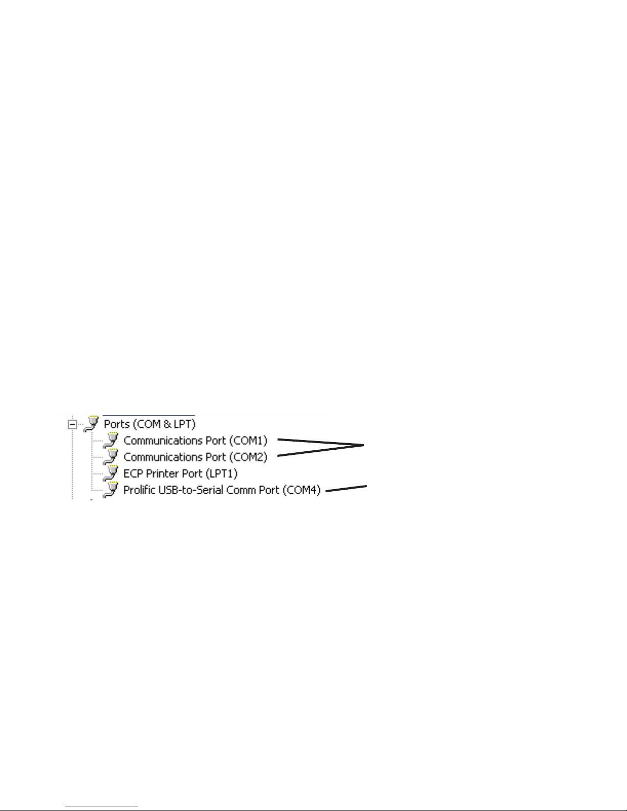
6. After clicking on ‘Ports (Com & LPT), one or more items will be shown. Look for the item
that refers to your USB to Serial Adapter, it will be something like ‘Prolific USB to Serial
Com Port (COM4)’ or ‘Belkin Serial Port (COM6)’. Note which COM port number has
been assigned to the USB to Serial Adapter .
Hardware COM Ports
USB to Serial Adaptor
(USE THIS ONE)
7. Close all open windows.
8. Launch the JW Fishers Sonar application
9. A message box will appear stating “Unable to Open Serial Port. Select Cancel to work
Offline”. Select “Cancel”.
10.Open the “Settings” Menu and select “Select Serial Port Number”
1 1.Select the COM port number that matches the COM port number found in step 6. (If
more than one COM port was listed, try each one until you find the one that works.)
The JW Fishers Sonar COM settings are now configured.
*Note:
If the USB to Serial Adaptor is inst alled in a different (physical) USB port, the COM port
number changes and you will have to repeat these steps to reconfigure the COM settings.
41

Troubleshooting (continued)
Problem: “A Required Interface Board Was Not Found” message
JW Fishers Sonar systems use an interface board to capture the analog sonar signal and
convert it to digital data which the software can then process. The driver software for this interface
board is installed as part of the JW Fishers Sonar application installation process. After the JW
Fishers Sonar application installation process is completed and before the sonar system is run for
the first time, a program to configure the interface board must be run. This program must also be
run whenever the Sonar Processor is used with a different PC.
USB Systems:
The SP to PC Interface (USB) Cable must be connected to the Sonar Processor and PC
1. From the Start menu select Programs / Measurement Computing / InstaCal.
2. The InstaCal software starts.
3. A ‘Plug and Play Board Detection’ window should open. USB-1208HS should show in the
window. Click ‘OK’
4. ‘Board #0 - USB-1208HS’ should show in the board list window .
5. From the ‘Install’ pull-down menu click on ‘Configure’. The ‘Board Configuration’ box opens.
6. Next to ‘Number of Channels’, select ‘8 Single Ended’. From the drop down list.
7. Click ‘OK’ to continue.
8. Exit the InstaCal program.
PC-CARD (older) systems
The PC-CARD Interface Board must be Installed in the PC
1. From the Start menu select Programs / Measurement Computing / InstaCal.
2. The InstaCal software starts.
3. In the ‘PC Board list’ click on ‘PC-CARD-DAS16/330’ to highlight it.
4. From the ‘Install’ pull-down menu click on ‘Configure’. The ‘Board Configuration’ box opens.
• Next to ‘Clock 0 Source’, select ‘Internal’.
• Next to ‘Clock Speed’, select ‘10MHz’.
• Next to ‘ADC External Pacer Edge’, select ‘Rising’.
• Click ‘OK’ to continue.
5. From the ‘Calibrate’ pull-down menu click on ‘A/D’. The automatic calibration will begin.
Allow the calibration to complete. When calibration is complete, click ‘OK’.
6. Exit the InstaCal program.
The interface board is now configured.
42

Troubleshooting (continued)
PC-CARD (older) systems only
Problem: On certain range settings the monitor seems to show a mirror image in a split
screen. Why does it do this?
The SCAN-650 software allows the operator to optimize sweep speed to match the speed
of the computer. This is accomplished using the Sweep Speed slider . If the sweep speed setting
is too fast, Sonar pings are not recorded by the PC. This will result in the mirror image. Slowing
down the sweep speed will correct this problem. Please note this adjustment must be made for
each Range setting / degrees per Step combination.
Problem: Sometimes my sweep speed had to be all the way down to get a full screen on
step setting 0.5. Is this normal?
The latest version of software has improved performance and should allow faster sweep
speeds. A new version of the SCAN-650 software is available for download. The latest version of
software offers improved performance and fixes several minor bugs found in earlier revisions.
Contact JW Fishers for information on software updates.
PH (800) 822-4744
PH (508) 822-7330
E-MAIL: jwfishers@aol.com or info@jwfishers.com
43

APPENDEX A
CONFIGURING YOUR GPS
The SCAN-650 uses standard NMEA 0183 information obtained from a connected
GPS or Loran C receiver to display your boats heading and position (Latitude and
Longitude). For most GPS systems you will need to enable the data output, select a
version of NMEA 0183 to output and select the outputs baud rate (data speed). These
selections are usually made through your receivers Setup menu. Please refer to your
GPS or Loran C users manual for detailed instruction.
NMEA 0183 Standard version – The NMEA 0183 interface standard has evolved to
accommodate new technologies in communications for marine navigation. As a result,
most GPS receivers offer a choice of which NMEA 0183 revision is sent to its data
output. The SCAN-650 can obtain the boats position and heading information from a
variety of data sentences available in many of the revisions. The sentences the SCAN650 recognizes are GLL, GGA, VTG and RMC. It is usually best to select the latest
revision. If, after selecting a revision, either the position or heading is missing, try
selecting another revision.
Baud rate – The SCAN-650 uses the industry standard speed of 4800 baud for the
NMEA 0183 interface. If your receiver offers a selection of alternate baud rates, select
4800.
44

APPENDEX B
USB TO SERIAL ADAPTOR
Windows XP
1. Load the driver software for the USB to Serial Adapter. Follow the manufacturers
instructions. Leave the adapter connected to the PC. Skip this step if it has already
been done.
Complete the following steps to open the ‘Device Manager’ on your PC. These steps
are necessary to find out what ‘Com Port Number’ the PC has assigned to the adapter’s
USB connection.
2. Select ‘Start’ and choose ‘My Computer’.
3. Under ‘Other Places’, select ‘Control Panel’.
If the ‘Pick a Category’ widow opens, select ‘Printers and other hardware’.
In the ‘See Also’ list, select ‘System’.
If the ‘Classic View’ window opens, select ‘System’.
4. In the ‘System Properties’ window, select the ‘Hardware’ tab.
5. Select ‘Device Manager’
6. In the Device Manager window a list of your computers hardware will be shown.
Click on ‘Ports (Com & LPT)’. If this is not shown, make sure the USB to Serial adapter
is plugged into the USB port and its software driver is correctly installed.
After clicking on ‘Ports (Com & LPT), one or more items will be shown. Look for the
item that refers to your USB to Serial Adapter, it will be something like ‘Belkin Serial
Port (COM6)’ or ‘Prolific USB to Serial Com Port (COM4)’. Click on this item.
7. When the ‘Properties’ window opens, select the ‘Port Settings’ tab.
8. Change the ‘Bits per Second’ to 4800.
9. Click the ‘Advanced’ button.
10. At the bottom of the ‘Advanced settings’ window, click on the ‘Com Port Number’
selection and select COM1, COM2, COM3, or COM4. It does not matter which one as
long as it is not listed as (in use). Note which COM port you selected and click ‘OK’.
11. Close all open windows.
Windows 98SE NEXT PAGE
45

APPENDEX B (continued)
USB TO SERIAL ADAPTOR
(continued)
Windows 98SE
1. Load the driver software for the USB to Serial Adapter. Follow the manufacturers
instructions. Leave the adapter connected to the PC. Skip this step if it has already
been done.
Complete the following steps to open the ‘Device Manager’ on your PC. These steps
are necessary to find out what ‘Com Port Number’ the PC has assigned to the
adapter’s USB connection.
2. Click on ‘My Computer’.
3. Select ‘Control Panel’. Select ‘System’.
4. In the ‘System Properties’ window, select the ‘Device Manager’ tab.
5. In the Device Manager window a list of your computers hardware will be shown.
Click on ‘Ports (Com & LPT)’. If this is not shown, make sure the USB to Serial
adapter is plugged into the USB port and its software driver is correctly installed.
After clicking on ‘Ports (Com & LPT), one or more items will be shown. Look for the
item that refers to your USB to Serial Adapter, it will be something like ‘Belkin Serial
Port (COM6)’ or ‘Prolific USB to Serial Com Port (COM4)’. Make note of the COM
number; you will need it when operating the SCAN-650 software. Click on this item.
6. When the ‘Properties’ window opens, select the ‘Port Settings’ tab.
7. Make the following selections in the Port Settings tab:
Bits per second = 4800
Data Bits = 8
Parity = None
Stop bits = 1
Click ‘OK’
8. Close all open windows.
46

MAINTENANCE
Your SCAN-650 was designed to be maintenance free. The scanning head, electronics housing and cable are constructed of corrosive resistant materials. Protect the
black scanning head. Do not sit the unit down on the black scanning head. The scanning head should be keep clean (soap and water), protected from damage, and stored
in a cool, dry place. The Sonar Processor, interface cables, and connectors should be
kept clean, dry, and out of direct sunlight.
The o-ring in the cable connector on the transducer can be lubricated with a silicon
based lubricant.
LIMITED WARRANTY
Your SCAN-650 underwent constant inspection during assembly to insure many years
of trouble free performance. The system is warranted for TWO FULL YEARS from the
date of purchase. During this period the SCAN-650 will be repaired free of charge
should a failure occur due to materials or workmanship under normal use.
The warranty does not cover damage due to dropping or general misuse. The warranty covers JW Fishers equipment only. JW Fishers will not be liable outside of the
remedies stated above.
Should service be required, write or phone us explaining the nature of the problem.
Most problems can be isolated over the phone and correct replacement parts sent to
you. In some cases, it may be necessary to return a system component for checkout.
RETURNING EQUIPMENT FOR REPAIR
If your SCAN-650 should need service, please call, fax, write, or e-mail:
info@jwfishers.com, phone (508) 822-7330, or fax (508) 880-8949 the factory for
instructions. We do not require authorization for the return of equipment. If you have
a problem with your sonar and would like to have it checked out at the factory, simply
pack it well and return with a brief note describing the problem.
Be sure to include your return address and telephone number on the note. When
returning equipment from outside of the US, to avoid Custom problems when arriving
in the USA, contact the factory for specific instructions regarding shipping.
Contact the factory for instructions should you encounter any problems. See cover
page for contact information.
47
 Loading...