

Page 1
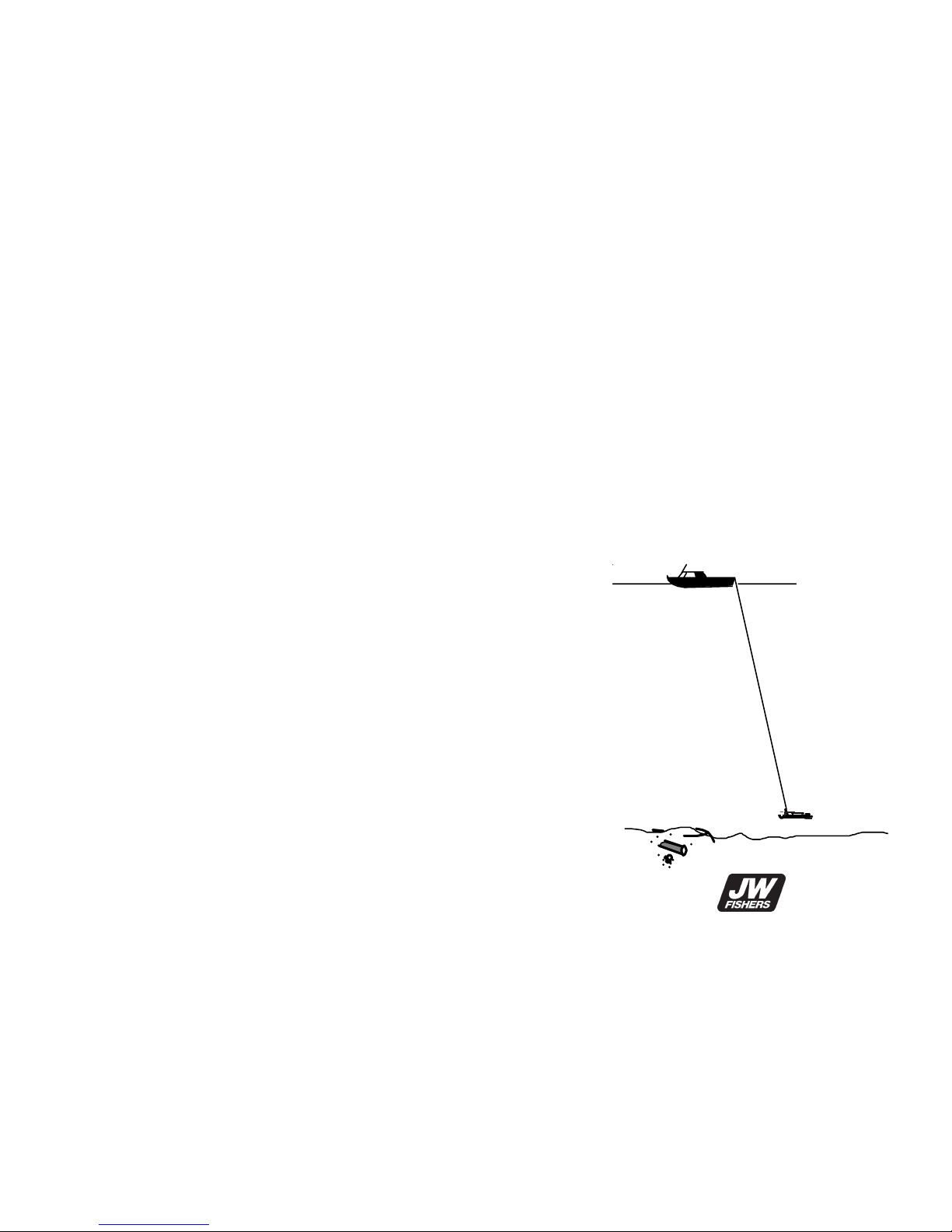
PULSE 12
BOAT TOWED PULSE DETECTOR
OPERATION MANUAL
1009
JW FISHERS MFG INC
1953 COUNTY ST.
E. TAUNTON, MA 02718 USA
(508) 822-7330; (800) 822-4744; FAX (508) 880-8949
Email: [email protected] WEB: www.jwfishers.com
Page 2

SENSITIVITY ( see page 3 for details ):
i
SPECIFICATIONS
Sensitivity (in water): Fresh Salt
Sample Pulse Delay 0 0 5
• Piece of eight ............................... 17 in ................. 9 in.... 4 in.
• 25 lb. lead ingot ........................... 40 in ............... 32 in. . 31 in.
• One gallon can ............................... 6 ft ................. 4 ft. .... 4 ft.
• Automobile ................................... 13 ft ............... 12 ft. .. 12 ft.
• Ship (max. range) ......................... 16 ft ............... 14 ft. .. 14 ft.
PERFORMANCE/DESCRIPTION:
• Detection area .......................................... 14 ft deep, 21 ft wide
• Tow speed ..................................................................... 1-6 mph
• Input voltage .................................................................... 24 vdc
• Power consumption .............................................................. 7 w
• Readout ........................................................... Meter and Audio
DIMENSIONS/WEIGHT:
• Coil ......................................... 24"Wx36"L ....................... 10 lbs
• Fish ......................................... 4' Lx6"Dia ....................... 20 lbs
• Control Box ......................... 13"Lx13"Wx6"H ..................... 5 lbs
• Cable ................................. .75"Dx150'/300' ............. 30/60 lbs
• Shipping Boxes -fish .......... 53"Lx15"Dx13"H .................. 50 lbs
-coil,cable,CB ............... 28"Wx10"Dx41"L .................. 75 lbs
MATERIALS/COLOR:
• Fish ...................................... High impact PVC, stainless/yellow
• Control Box ...................... High impact Pelican case, PVC/black
• Cable ................................. 8 conductor in polypropylene/yellow
• Coil ............................................ High impact PVC, epoxy/black
OPTIONS
• Additional Search Coils • RS232 computer interface
• 300 ft cable
• Altimeter
LIMITED WARRANTY
Your unit underwent constant inspection during assembly to insure many
years of trouble free performance. The PULSE 12 is warranted for TWO
FULL YEARS from the date of purchase. During this period, your unit will
be repaired free of charge should a failure occur due to materials or
workmanship. The Warranty does not cover broken cables or coils, or
damage due to droppage or general misuse.
Should service be required, write/phone us explaining the nature of the
problem, and we will supply shipping instructions. All repairs are made at
our factory. Repairs by unauthorized persons may void the Warranty.
Page 3
INTRODUCTION
The PULSE 12 is a boat-towed pulse induction metal detector.
Though it was primarily designed to locate large metal objects, it will
detect small targets though not at great distances. Pulse detectors
have been around since the mid 1970's and have had a major
impact on the search and salvage business. Their major claim to
fame is that they are very sensitive and do not generally detect
minerals (extreme concentrations of iron ore may give a modest
reading). This lack to mineral detection is an answered prayer for
salt water divers who have to contend with heavy mineralized
deposits on the ocean floor which produce large false readings on
conventional detectors. Pulse detectors, with small and medium
size coils, ignore these mineral deposits and respond only to metal
targets (ferrous and non-ferrous metal). The Pulse 12, with its very
large coil, has a Sample Pulse Delay Knob which enables the
operator to "tune out" most minerals. Pulse detectors work well on
land and in fresh or salt water.
HOW PULSE DETECTORS WORK
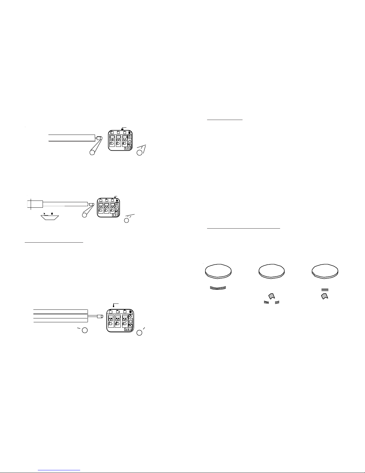
Pulse detectors operate by transmitting a continuous stream of high
energy magnetic pulses (one hundred per second), from the Coil.
After each pulse is transmitted, the unit then "listens" using the Coil
as the receiving antenna.
Figure 1
When a transmitted pulse hits a metal object, a magnetic field is
induced in the object. This causes eddy currents to flow in the metal,
which in turn generates a second magnetic field. This field is picked
up by the Coil, amplified, and then displayed by the meter and heard
in the speaker/earphone.
1
PULSE
COIL
NOTE: The transmitted
pulse covers a much
larger area than shown
above.
EDDY CURRENTS
COIL COIL
RECEIVE
target
ANALOG OUTPUT OPTION
The analog output option allows the Pulse 12 to be connected to an
external device such as a strip chart recorder or data logger. The
analog output consist of 3 channels (one for each towfish) who's
output is 0 to +4.00vdc. The voltage is a representation of the
detection signal strength.
The analog output uses 4 wires and is wired to a 5 pin DIN connector
on the Pulse 12 as Follows:
LORAN C / GPS WIRING
RS232 WIRING
ANALOG OUTPUT WIRING
FISH 1 FISH 2 FISH 3
AUDIO
POWER
JW FISHERS MFG
1953 County St
E. Taunton, MA 02718
pin 1
Not used
1
2
3
4
5
Enlarged front view of 5 pin
connector . Pin 5 not
used.(PIN END)
fish 1 red
fish 2 green pin 2
whitefish 3
pin 3
ground
black
pin 4
Analog output (0-4vdc)
Not used
123
45
5 pin socket
in box
5 pin DIN
Connector
in Pulse 12
Control Box
12
1
2
3
(with 0183 interface)
LORA N C/GPS
Signal
Return (shield)
Red
Black and S hield
No te: con nect
shield to black wire
at b oth en ds
(+)
(-)
Enlarged front view
of 3 pin connector
(PIN END)
5 pin DIN
Connector
in P uls e 1 2
Control Box
Loran /G P S
5 pin socket
in box
1
2
3
45
Not used
FISH 1 FISH 2 FISH 3
AUDIO
POWERJW FISHERS MFG
1953 County St
E. T a unton , MA 027 1 8
FIS H 1 FISH 2 FISH 3
AUDIO
POW ERJW F IS H E R S M F G
195 3 C o unty St
E. Taunton , MA 02718
5 pin DIN
Connector
in Pulse 12
Control Box
RS232
Red
Black and Shie ld
RS232
Interface
9 pin "D"
fe mal e
connecto r
pin 2
pin 5
No t used
5 pin socket
in box
123
45
3
En larged fron t view
of 3 pin co nn ecto r
(PIN END)
1
2
5
2
END VIEW
White
Page 4
PULSE 12 DESCRIPTION
The PULSE 12 is a boat-towed pulse detector consisting of an 24"
by 36" Coil, a towable Fish (removable for land use), a Pre-amp, a
150/300' Cable, and a Control Box. The Control Box can support
one, two, or three Fish; all being towed at the same time. If you
purchased a single Fish, you can add additional Fish at any time.
Figure 2
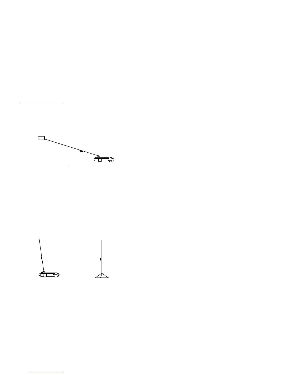
For underwater use, the Coil is mounted on the Fish and is towed
at any depth down to 150/300 ft. The Fish sails through the water at
a depth determined by the speed of the boat and the amount of
cable let out. The dynamics of the Fish is that it tows very flat and
directly below the boat ( see Figure 3a ). As more cable is let out, or
the speed of the boat increases, the Fish tows further behind the
boat. An increase in boat speed results in reduced fish depth. If
towing in deep water, a downrigger ( 25# of lead ) can be added to
the line to insure maximum depth for the Fish ( see Figure 8b ).
For pinpointing, or for very small search areas, the coil can be
disconnected from the fish and suspended over the side of the boat.
A simple three point harness, made out of rope, insures that the coil
remains flat ( see Figure 3b ).
2
Control box
150/300' cable
Pre-amp
Coil
Fish
Figure 3b
Cable to
boat
Figure 3a
Cable to
boat
If only one towfish is being used, the readings for Fish 2 and Fish
3 will be approximately 150mv.
If a GPS or Loran C is not being used, or if the GPS or Loran C
message is not being properly received by the Pulse 12 the
message will be as follows:
@ NO POSITION AVAILABLE, Fish 1=,3270,Fish 2=,1650,
Fish 3=,350<cr><lf>
When using the Pulse 12 with a Loran C or GPS receiver the
following connection and power-up sequence must be followed for
proper operation.
1. Cable up entire system including GPS/Loran C to Pulse
12, Pulse 12 to the computer (RS232 interface), and
Pulse 12 towfish to Pulse 12 control box. Also connect
all components to their proper power sources.
2. Power-up GPS/Loran C and obtain current position fix.
3. Power-up computer.
4. Power-up Pulse 12
5. Initiate data collection program on computer.
If the Pulse 12 is powered up before the GPS has obtained the
current position or the GPS interface cable is disconnected, the
RS232 interface will default to the "No Position Available" message
s shown above.
If the GPS/Loran C loses its position fix during operation, the Pulse
12 will default to the "No Position Available" message".
If either of these conditions occur correct the fault (re-initialize the
GPS, check connections, check battery condition). Once the GPS/
Loran C is again functioning properly, power down the Pulse 12,
wait five seconds and power up the Pulse 12. The position
information should now be present.
11
Red
Page 5
BATTERY SELECTION
The PULSE 12 draws approximately .3 amp at 24v. Two car type
batteries will last several days of continuous use. For good
portability, two motorcycle type batteries can be used, with a
minimum of 8 hours between charges. Battery status can be
checked at any time by pressing the Batt Ck switch upward and
observing the Fish 1 meter for a reading of .7 to 1.
MAINTENANCE
Please write/phone the factory at (508) 822-7330 if any problems.
RS232 /GPS/ANALOG OPTION
With the RS232 option the Pulse 12 can be connected to any
computer or data recorder equipped with an RS232 input. The
specification of the interface is as follows: 8 bit, 4800 baud rate, 1
stop bit, and no parity bit.
The GPS/Loran C interface allows the ships position information to
be input into the Pulse 12. The Pulse 12 then reformats the
information, combines it with the signal strength readings from the
towfish, and sends it to an external computer via the RS232
interface.
Any GPS or Loran C receiver equipped with a NMEA 0183 output
can be used with the Pulse 12. If you are not sure if your receiver
has NMEA 0183 output, check its manual or call the manufacturer.
You may find that you have to tell your GPS receiver to send out the
0183 information (refer to your GPS manual). If given a choice,
select 0183A or 0183C format. Both versions include the latitude/
longitude message format called GLL. The Pulse 12 can also
receive the message format called GGA, if the message GLL is not
available. The Pulse 12 automatically checks for the presence of
either message on power-up.
The sample message sent on the RS232 interface is as follows:
@Position, 4151.745353, N, 07102.394576, W,
Fish 1=,3270, Fish 2=,1650,Fish 3=,350<cr><lf>
Where the position is the latitude and longitude coordinates from the
GPS or Loran C receiver and "Fish 1", "Fish 2", and "Fish 3" are the
detection signal strengths expressed from 0 to 5,000 millivolts (0 to
5.000 volts). The complete message is repeated once per second.
GAL CAN
6'
MAX RANGE
16'
DRAWN
TO SCALE
DETECTION
AREA FOR
SINGLE COIL
9'
24'
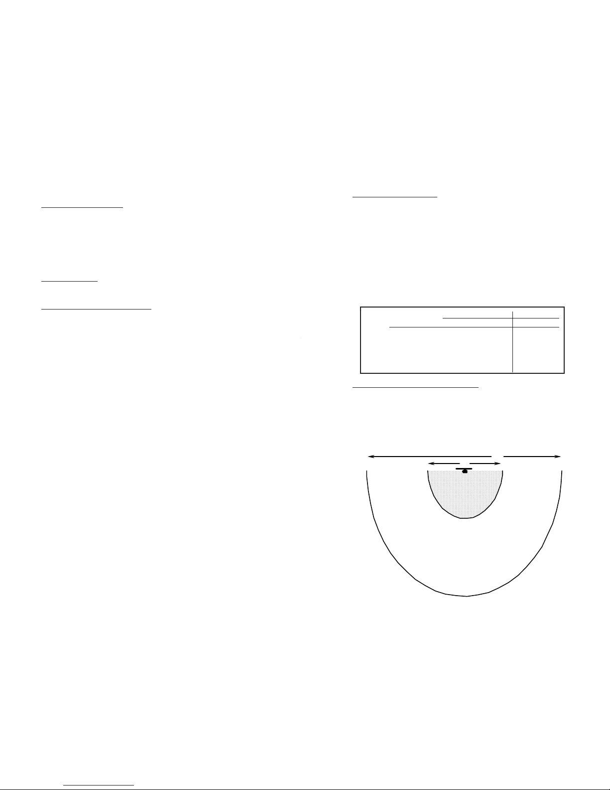
MAX DETECTION ENVELOPE ( fresh water )
PULSE 12 SENSITIVITY
The sensitivity of the Pulse 12 is switch selectable and is dependent
on whether it is operating in fresh or salt water. If operating in fresh
water (or on land) you can expect detection ranges as indicated
under Fresh in the chart below. When operating in salt water, you
can expect detection ranges as indicated under Salt in the chart
below. When operating in salt water, a second switch Sample
Pulse Delay is used to "adjust out" the salt water impact on the large
Pulse 12 coil. The Sample Pulse Delay setting does impact the
detection range on smaller targets, but has little impact on larger
targets. You can expect these detection ranges whether the target
is buried under mud, coral, sand, or rocks.
Sensitivity (in water): Fresh Salt
Sample Pulse Delay 0 0 5
• Piece of eight ............................... 17 in ................. 9 in.... 4 in.
• 25 lb. lead ingot ........................... 40 in ............... 32 in. . 31 in.
• One gallon can ............................... 6 ft ................. 4 ft. .... 4 ft.
• Automobile ................................... 13 ft ............... 12 ft. .. 12 ft.
• Ship (max. range) ......................... 16 ft ............... 14 ft. .. 14 ft.
PULSE 12 DETECTION ENVELOPE
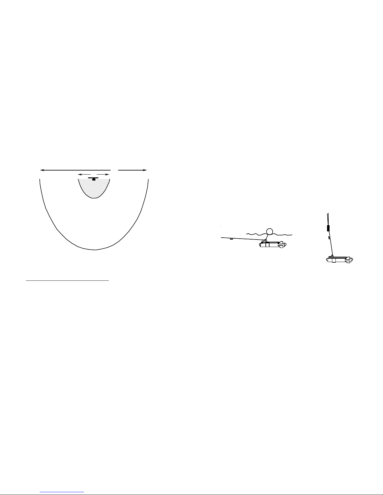
The detection envelope for the PULSE 12 is very large - much larger
than the coil width/length. Figures 4a,b shows the fresh and salt
water detection envelopes for a one gallon can and for the maximum detection envelope (a very large object). Though it is not
shown, the envelopes exist above the coil as well as below.
3
Figure 4a
10
Page 6
GAL CAN
4'
MAX RANGE
14'
DRAWN
TO SCALE
DETECTION
AREA FOR
SINGLE COIL
6'
21'
MAX DETECTION ENVELOPE ( salt water )
4
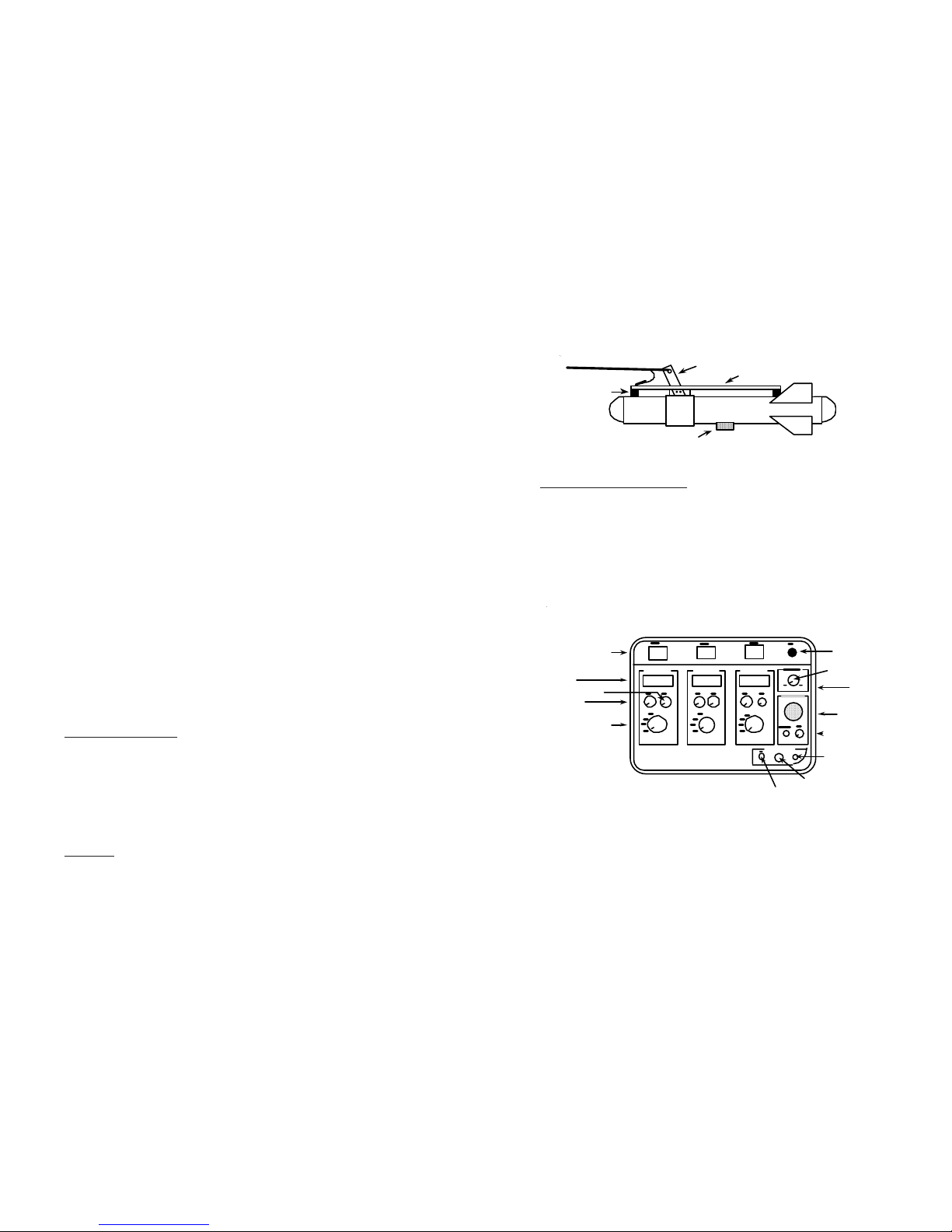
PULSE 12 ASSEMBLY ( coil and fish )
Note: All hardware must be of stainless steel. Stainless is not
detectable by almost all kinds of metal detectors.
1. The Tow Arm is bolted to the Fish using two 1/4 - 20x1" stainless
steel bolts, washers, and nuts. Tighten securely, be sure lock
washers are under nuts and tow arm points forward.
2. The Coil mounts to the Fish with four 2" ID X 1/8" O-ring. Be sure
to mount Coil so that the cable is close to the Tow Arm (front of
fish). Stretch the O-rings over the coil and hook them around the
head of the screws protruding out of the front and rear of the coil
supports.
3. Connect the Tow Cable/ rope to the shackle at the top of the Tow
Arm.
The salt water detection envelope is somewhat smaller than the
fresh water detection envelope. This was necessary to reduce
the impact ( meter movement ) of salt water on such a large
search coil.
Figure 4b
9
If your target is small (small anchor, motor, etc.), a slow tow speed
is recommended. If the target passes too quickly below the Coil, you
may get a weak reading on the meter. Experiment by passing a one
gallon can past the Coil while on land. It is recommended that you
use a 1/4" rope between the boat and the downrigger. The
downrigger should be connected to the boat on its own line, so not
to put excessive strain on the Cable. The cable is taped, or wire wrap
tied, to the rope every foot or so. When towing more than one Fish,
a separate downrigger is used for each Fish.
When towing in a highly mineralized area, it will be necessary to
operate in the Salt mode, with the Sample Pulse Delay at four or five.
In this position the effect of minerals is held to a minimum. This
control effects sensitivity for smaller objects - see chart on page 3.
If the control is not set high enough in mineralized areas, then the
meter will move around more than necessary. The meter movement
is caused by the constantly changing distance between the bottom
and the coil as it is being towed close to the bottom.
Cable to
boat
Float
Figure 8b
Figure 8a
Downrigger
25-50#
Downrigger
line from
boat
Cable to
boat
Altimeters attach to the bottom of a Fish and measure the distance
to the bottom. If you did not purchase the Altimeter, then the tow
rope should be marked every five ft and used in conjunction with
your boat depth finder to control Fish depth.
Shallow water ( 2 to 6 ft ) searching is accomplished by tying a float
to the fish ( see Figure 8a ) so that it can be towed behind the boat
without the Fish running into the bottom.
Deepwater searches (over 75 ft ) require a downrigger ( see Figure
8b ) to insure maximum depth of the Fish. The downrigger can be
of any weight - a 25 pound ingot of lead does a good job at low speed
(2-4 MPH). The faster or deeper you tow, the heavier the weight
must be for the Fish to stay directly below the boat to enable
accurate depth control.
Page 7
- Turn the Selection Switch for all unused Fish to the Off position.
- Push the Batt. Ck. momentary toggle switch upward, and note
that the Fish 1 meter reads .7 to 1 which indicates Batts are ok.
- Set the Sample Pulse Delay knob to 0 for fresh water, or to 4 for
salt water use.
- Turn the Selection Switch for Fish 1 to Cal. and adjust the Cal.
Adjust knob until meter reads approximately .3.
- Turn the Selection Switch for Fish 1 to Salt or Fresh position
(depending where you will be using the detector).
- Adjust the Zero Adjust knob for a meter reading of approximately
.1. The actual needle position is not important as long as it is
above zero. Some meter movement, especially while towing, can
be expected.
- Fish 1 is ready to go. Periodic adjustment of the Zero Adjust knob
may be necessary. Each time you turn on the Control Box, the Cal
should be rechecked for a reading of approximately .3. The above
procedure is repeated for each Fish.
- Before proceeding to connect up the remaining Fish ( if you have
them ), run some tests with a metal target ( gal can is fine ) to get
the feel of the Pulse 12. There is no need to move the coil, simply
move the target around, above or below the Coil.
DETECTING METAL
As metal passes near the Coil, the needle swings up. At about a .2
meter reading the audio sounds off and increases in pitch (frequency) as the needle swings higher. Maximum meter swings
occur when the target is directly below the center of the Coil. As you
go past the target, the needle returns to zero and the audio stops.
TOWING
The Fish tows flat and directly below the boat. When searching in
water 6 to 75 ft deep this works quite well. The objective is to get
the coil as close to the bottom as possible so the target will not be
missed. The ideal tool to do this with is an Altimeter.
8
PULSE 12 CONTROL BOX
The heart of the system is the Control Box ( see Figure 6 ) which
contains all controls and indicators for the system. The Control Box
can handle up to three Fish. The Fish are interchangeable and can
be plugged into any Fish connector on the control Box. Each Fish
has its own controls ( Selection switch, Zero Adjust knob, and Cal
knob ), and meter which indicates a target has been detected by that
Fish.
5
• 24 vdc Input Connect this cable to 24 vdc (see Figure
7). Supplies power to the complete system.
• Power On Switch Turns power on to the complete system.
• Power On LED Lights when power has been turned on.
Figure 6
4. If you have purchased the optional Altimeter, bolt it to the bottom
of the Fish. See the UA-2 operation manual for it's connection
and use.
J W FISHERS MFG INC
BERKLEY, MA 02779
65 ANTHONY ST
FISH 1 FISH 2 FISH 3
AUDIO
POWER
24 vdc Input
Speaker
Vol Control
Earphone Jack
Power On LED
Power On Switch
Batt Check Switch
Fish Connectors
Meters
Cal Knob
Zero Adj Knob
Selection Switch
Control Bo
x
Sample Pulse
PULSE 12
Coil Support
Coil
Tow Arm
Altimeter
Figure 5
Page 8

• Batt Check Switch When depressed upward, displays condition of batts on meter number 3. If batts
are ok, meter will indicate .7 to 1.
• Fish Connectors One, two, or three Fish cables can plug
into the Control Box. Power should be off
when plugging in cables. When the Fish is
plugged into a Connector, it is controlled
by the controls directly below that connector.
• Meters Each Fish has its own meter. When a
metal target is detected, the meter swings
up. At a given distance, a small target will
produce a smaller swing on the meter than
a large target.
• Selection Switch A four position switch which selects the
mode of operation for each Fish.
OFF - When in this mode the Fish and all
controls have no effect on the system. All
unused Fish connectors must have Selection switch in the Off position.
CAL - When a Fish is plugged into a
connector it must be calibrated before
being used.
SALT - This position is used for searching
in salt water.
FRESH - This position is used for searching on land or in fresh water. This position
gives the search coil the maximum sensitivity available.
• Cal Knob When the Selection switch is in Cal position this knob is used to adjust the meter to
approx .3 on the scale. The Fish is now
calibrated and ready for searching in the
Salt or Fresh position.
6
OPERATION/CHECKOUT
- Position the coil outside and 5-6' away from any metal.
- Plug the cable from the coil into the Fish 1 connector on the control
box.
- Connect the power cord to 24 vdc ( two 12v car/motorcycle
batteries in series ) and observe polarity.
- Turn the Power Switch on and note that the LED is illuminated.
7
• Zero Adjust Knob When the Selection switch is in Search
mode, the Zero Adjust is used to set the
meter to approx .1 on the scale. The Fish
is now ready for searching.
• Sample Pulse Delay Used to reduce the effect (meter move-
ment) of highly mineralized salt water bottoms. Set to zero for land and fresh water,
four or five for salt water. Effects sensitivity
for small targets - see chart on page 3.
• Speaker When a target is detected by any Coil, the
meter swings up from the .1 position. As it
goes past .2 the speaker sounds off. The
higher the meter goes, the higher the pitch
(frequency) out of the speaker.
• Vol Control Adjusts the volume out of the speaker.
• Earphone Jack Accepts a standard 1/4" earphone plug
(stereo or mono). Speaker output stops
when earphones are plugged in.
Figure 7
+
-
+-
12v
12v
To Control Box
Red
clip
+
(2) car batt.
 Loading...