


Integrated Step Motors,
QuickStep,
MIS231, MIS232, MIS234,
MIS340, MIS341, MIS342,
MIS430, and MIS432
Including Step Motor Controller
SMC75, SMC85
User Manual
JVL Industri Elektronik A/S
LB0053-22GB Revised 25.th. January 2016

Important
User Information
!!
The MIS and SMC series of products are used to control electrical
and mechanical components of motion control systems.
You should test your motion system for safety under all potential
conditions. Failure to do so can result in damage to equipment
and/or serious injury to personnel.
Please contact your nearest JVL representative for technical assistance. Your
nearest contact can be found on our web site www.jvl.dk
Copyright 1998-2016, JVL Industri Elektronik A/S. All rights reserved.
This user manual must not be reproduced in any form without prior written
permission of JVL Industri Elektronik A/S.
JVL Industri Elektronik A/S reserves the right to make changes to information contained in this manual without prior notice.
Furthermore JVL Industri Elektronik A/S assumes no liability for printing errors or other omissions or discrepancies in this user manual.
Warning
MacTalk and MotoWare are registered trademarks
JVL Industri Elektronik A/S
Blokken 42
DK-3460 Birkerød
Denmark
Tlf. +45 45 82 44 40
Fax. +45 45 82 55 50
e-mail: jvl@jvl.dk
Internet: http://www.jvl.dk

`зенЙенл
1 Introduction .................................................................................................................... 7
1.1 Non-programmable motors ............................................................................................................................... 8
1.2 Programmable motors ...................................................................................................................................... 10
1.3 General description .......................................................................................................................................... 12
2 Hardware - Intelligent products .................................................................................. 13
2.1 Power Supply .................................................................................................................................................... 14
2.2 Inputs ................................................................................................................................................................ 18
2.3 Analogue Inputs ................................................................................................................................................ 21
2.4 User Outputs .................................................................................................................................................... 25
2.5 Serial interfaces overview ................................................................................................................................. 27
2.6 RS485 Interface ................................................................................................................................................. 28
2.7 Special Outputs ................................................................................................................................................. 30
2.8 Special Connections .......................................................................................................................................... 32
2.9 Handling noise in cables .................................................................................................................................... 33
2.10 How to connect MIS23x ................................................................................................................................... 35
2.11 How to connect MIS34x ................................................................................................................................... 37
2.12 LED indicators at the MIS34x ........................................................................................................................... 53
2.13 LED indicators at the MIS34x ........................................................................................................................... 54
2.14 LED indicators at the MIS34x ........................................................................................................................... 55
3 Hardware Non-intelligent products ............................................................................. 57
4 Using MacTalk ............................................................................................................... 59
4.1 Using the MacTalk software ............................................................................................................................. 60
4.2 How to update MacTalk ................................................................................................................................... 68
4.3 How to update the motor firmware ................................................................................................................. 69
4.4 How to update the encoder firmware ............................................................................................................. 70
5 Description of functions ................................................................................................ 71
5.1 Adjusting the motor current ............................................................................................................................. 72
5.2 Auto Correction ............................................................................................................................................... 73
5.3 Absolute position back-up ............................................................................................................................... 75
5.4 SSI encoder/sensor interface ............................................................................................................................. 78
5.5 Absolute Multi-turn Encoder ............................................................................................................................ 85
5.6 Position Limits ................................................................................................................................................... 91
5.7 Mechanical Zero search .................................................................................................................................... 96
6 Modes ............................................................................................................................ 97
6.1 Passive Mode .................................................................................................................................................... 98
6.2 Velocity Mode ................................................................................................................................................... 99
6.3 Positioning Mode ............................................................................................................................................ 100
6.4 Gear Mode ...................................................................................................................................................... 101
6.5 Zero search modes ......................................................................................................................................... 110
7 Error Handling ............................................................................................................ 115
8 Registers ......................................................................................................................117
8.1 Introduction to registers ................................................................................................................................. 118
8.2 MIS23x Registers ............................................................................................................................................. 119
8.3 MIS34x & MIS43x Registers ............................................................................................................................ 154
JVL Industri Elektronik A/S - User Manual - Integrated Stepper Motors MIS23x, 34x, 43x 3

9 Building Sequential Programs .................................................................................... 189
9.1 Getting started with programming ..................................................................................................................190
9.2 Programming Main window ............................................................................................................................191
9.3 Programming menu .........................................................................................................................................192
9.4 How to build a program ..................................................................................................................................193
9.5 General programming hints .............................................................................................................................196
9.6 Command toolbox description ........................................................................................................................197
9.7 Graphic programming command reference ....................................................................................................198
10 CANopen Introduction ............................................................................................... 217
10.1 General information about CANopen .............................................................................................................218
10.2 Connection and setup of the CAN bus ...........................................................................................................222
10.3 Using CANopenExplorer ................................................................................................................................226
10.4 Objects in the DS301 standard ........................................................................................................................231
10.5 Objects used in the DSP-402 standard ............................................................................................................241
10.6 Flexible Register setup .....................................................................................................................................248
10.7 More details of CANopen Theory ..................................................................................................................249
11 Modbus interface ........................................................................................................ 261
11.1 Modbus in MIS34x and SMC85 ........................................................................................................................262
12 Stand alone electronics .............................................................................................. 265
12.1 Step motor drivers (SMDxx) ...........................................................................................................................266
12.2 Step motor controllers (SMCxx) .....................................................................................................................268
12.3 How to connect the motor .............................................................................................................................273
12.4 How to connect in general ..............................................................................................................................276
12.5 Quick Start (SMC75A1MxAA) .........................................................................................................................277
13 Technical Data ............................................................................................................ 278
13.1 MIS23x Technical Data ....................................................................................................................................279
13.2 MIS34x Technical Data ....................................................................................................................................280
13.3 SMC75 Technical Data ....................................................................................................................................281
13.4 Torque Curves ................................................................................................................................................282
13.5 Physical Dimensions ........................................................................................................................................284
13.6 Life time ...........................................................................................................................................................287
13.7 Trouble-shooting guide ...................................................................................................................................288
14 Connection to other Equipment ................................................................................ 289
14.1 Connecting SMI30/SMC35 to MIS/SMC75 ......................................................................................................290
14.2 Connecting MISxx/SMC75 to SMD73 .............................................................................................................291
14.3 Connecting MISxx/SMC75 to SMD41 .............................................................................................................292
14.4 Connecting MISxx/SMC75 to MAC00-Bx .......................................................................................................293
14.5 Connection to PLC/PC Boards .......................................................................................................................294
15 Accessories .................................................................................................................. 295
15.1 Cables ..............................................................................................................................................................296
15.2 Power Supplies ................................................................................................................................................297
15.3 Brakes and shaft reinforcement .......................................................................................................................298
15.4 Gear and brake mounting instruction ..............................................................................................................299
16 Appendix ..................................................................................................................... 301
16.1 MIS23x & SMC75 Registers detailed ...............................................................................................................302
16.2 MIS34/43/SMC85 Registers detailed ................................................................................................................312
16.3 Velocity accuracy .............................................................................................................................................322
16.4 Command timing .............................................................................................................................................323
16.5 More about program timing ............................................................................................................................324
16.6 Motor Connections .........................................................................................................................................325
16.7 Serial communication ......................................................................................................................................327
16.8 MIS Ordering Information ...............................................................................................................................332
4 JVL Industri Elektronik A/S - User Manual - Integrated Stepper Motors MIS23x, 34x, 43x

16.9 SMC75/85 Ordering Information .................................................................................................................... 333
16.10 MST Motor Ordering Information .................................................................................................................. 334
17 Declarations ................................................................................................................ 336
17.1 CE Declaration of Conformity ........................................................................................................................ 337
17.2 Vibrationtest certificate MIS23x ...................................................................................................................... 339
17.3 Vibrationtest certificates MIS34x .................................................................................................................... 340
17.4 Index ............................................................................................................................................................... 342
JVL Industri Elektronik A/S - User Manual - Integrated Stepper Motors MIS23x, 34x, 43x 5

6 JVL Industri Elektronik A/S - User Manual - Integrated Stepper Motors MIS23x, 34x, 43x

1 Introduction
MIS34x family
(MIS340 shown)
This user manual describes the set-up and usage of the following products:
Complete motors with build-in controller or driver
• Types MIS231, MIS232 and MIS234 (NEMA23 sizes)
• Types MIS340, MIS341 and MIS342 (NEMA34 sizes)
• Types MIS43x (NEMA43 sizes) - only limited supported in this manual.
MIS23x family
(MIS232 shown)
TT2317-01GB
Stand-alone electronics without motor
• Types SMD73 and SMD74 drive PCB without intelligence (not programmable)
• Types SMC75 and SMC85 controller PCB with intelligence (fully programmable)
All the quickstep motors are available as a fully programmable product with a wide range
of features also covering a simple pulse and direction interface.
The smaller quickstep motors size MIS23x are also available as a “non-programmable”
and more simple version with pulse and direction inputs for applications which are price
sensitive.
Examples of motors and stand alone electronics.
MIS342 and MIS340
Standard version
MIS340
with Bluetooth
MIS232
with step and direction input
SMC85A1
Step motor controller
MIS230-234
Standard version
SMC75A1
Step motor controller
SMD73
Step motor driver
TT2319-01GB
JVL Industri Elektronik A/S - User Manual - Integrated Stepper Motors MIS23x, 34x, 43x 5

1.1 Non-programmable motors
MIS231 Stepmotor
with pulse and direction input
TT2322-01GB
The QuickStep series of Stepper motors with integrated electronics represents a major step forward.
All the necessary electronics in a stepper system are integrated in the motor itself.
In the past, a traditional motor system has typically been
based on a central controller unit located remote from
the motor. This configuration however has the disad
vantage that installation costs are a major part of the total expense of building machinery.
The basic idea of the QuickStep motors is to minimize
these costs but also to make a component that is much
better protected against electrical noise, which can be a
typical problem when using long cables between the
controller and motor.
The stepper motor, encoder and electronics are specially developed by JVL so that together they form a
closed unit, in which the power driver and controller
are mounted inside the motor.
The advantages of this solution are:
• De-central intelligence.
• Simple installation. No cables between motor and
driver.
• EMC safe. Switching noise remains within
motor. (Noise can however be introduced in the
DI/DO).
• Compact. Does not take space in cabinet.
• Low-cost alternative to separate step or
servo motor and driver.
In the past decade, pulse/direction interfaces have become increasingly popular for the control of step and
servo motors. This is due to the fact that pulse/direction
signals provide a simple and reliable interface which is
100% digital, precise, and offers immediate response.
When a pulse is sent, the motor instantaneously moves
1 step forward.
For example, if the motor has a resolution of 200 steps/
revolution, it will move 1.8 degrees. By changing the
frequency of the applied pulse signal, it is possible to ac
celerate the motor.
-
By counting the number of pulses, the motor’s position can be determined without any error whatsoever. The direction input is used to determine
the motor’s direction of rotation. JVL’s QuickStep
motors with pulse/direction interface offer the fol
lowing advantages:
• Very simple technology that is easy to understand and apply.
• High stability and low cost because the technology is simple with few components.
• Only one cable with 4 wires is required, so
cabling costs are a minimum.
• No controller in the control cabinet.
• All positioning and control is performed by the
PLC, so there is no duplication of software or
cabling.
• Robust IP67 connector and IP55 motor housing
for applications in demanding environments.
• Thermally protected against current overload
and short-circuit.
• Reacts instantaneously. The motor starts within
microseconds.
• 5V or 24V PNP/NPN inputs ensure compatibility with any controller.
• Step resolution of 200, 400, 800, 1000 or 1600
pulses/revolution.
• Supply voltage 18-28VDC (based on SMD73).
• Supply voltage 18-48VDC (based on SMD74).
• Possibility for encoder feedback.
All the required electronics are integrated in the
motor itself in a single compact unit. The motor can
be supplied with the connector either on the back
or side of the housing. M12 connector is standard,
but cable glands or DSUB connector can be deliv
ered on request.
For further information on the pulse/direction
driver see also SMD73 Data-sheet and Tech
-
nical Note.
-
-
-
6 JVL Industri Elektronik A/S - User Manual - Integrated Stepper Motors MIS23x, 34x, 43x

1.1 Non-programmable motors
1.1.1 Block diagram, Pulse/Direction Version
r
o
t
c
e
n
n
o
18-28VDC (SMD73)
c
18-48VDC (SMD74)
y
l
p
p
u
s
r
e
w
o
P
n
o
i
t
c
e
r
t
i
u
d
p
d
n
i
n
a
p
e
t
S
t
u
p
t
u
O
r
e
d
o
c
n
E
Bus Supply
Ground
Stepclock
Direction
SMD73 or SMD74 Driver
200, 400, 800,
1000, 1600 step
Driver
High speed
digital logic
array
5V to 24V
PNP/NPN
Selector
Encoder
A
B
Phase A
Phase B
Optional
Motor
2-phase
stepper
motor
Incremental
encoder
TT2178-02GB
1.1.2 Driver Connections
Versions with pulse and direction control:
Connections for versions with 1 M12 connector. (See also SMD73 data-sheet)
M12 5 pin male Description JVL cable WI1000M12 F5TxxN
1 P+ (18-28VDC) Brown
2 Pulse White
3 P- Blue
4 Direction Black
5 Signal Ground Grey
xx: 05 for 5 metre and 20 for 20 metre cable.
Versions with cable glands and 5 m cable
Colour Code Description
Red P+ (18-28VDC)
Black P-
Blue Direction
White Pulse
Shield Signal ground
JVL Industri Elektronik A/S - User Manual - Integrated Stepper Motors MIS23x, 34x, 43x 7

1.2 Programmable motors
MIS232 with controller
The compact step motor controller SMC75
and SMC85 is designed for positioning and
speed control of stepper motors.
SMC75 is mounted directly in the housing of
the JVL QuickStep motors MIS 231, 232 and
234, and SMC85 is mounted in the MIS34x and
MIS43x, forming a complete integrated step
motor.
They may also be used with other types of step
motors according to customers requirements.
The basic features of the controller are:
• Serial RS485 or 5V serial position controller.
• Position controller with graphic programming.
• Option for CANbus, CANopen DS-301/
DSP-402 or DeviceNet (under develop
ment).
• A dual supply facility is available so that
position and parameters are maintained at
emergency stop.
• Gear mode.
• MACmotor protocol so MACmotor and
Quickstep motors can be connected on
the same RS485 bus.
• Command for easy PLC/PC setup and
communication.
• Power supply 12-48VDC.
• Fixed 1600 pulses/rev.
• Built-in 16Bit µprocessor (SMC75) and
32Bit µprocessor (SMC85) with 8 In/Out
that can be configured as inputs, PNP out
puts or analogue inputs. 5V serial and
RS485 interface for set up and program
ming.
•MODBUS interface.
• 9.6 to 1Mb communication.
-
-
• Driver technology is improved as compared to SMD73 and supply voltage is
12-48VDC.
When used with the QuickStep motor or
mounted on any other step motor the advantages of the controller are:
• De-central intelligence.
• Simple installation. No cables between
motor and driver.
• EMC safe. Switching noise remains
within motor.
• Compact. Does not take space in cabinet.
• Low-cost alternative to separate step
or servo motor and driver.
• Stall detect by means of magnetic
encoder with resolution of up to 1024
pulses/rev. (H2 option)
• Absolute multi turn encoder for keeping the position permanent also during
power down. (H3 option).
• Interface possibilities:
• From PC/PLC with serial commands via
5V serial or RS485.
• Pulse/direction input. Encoder output.
• CANopen, DeviceNet.
• 8 I/O, 5-28VDC that can be configured
as Inputs, Outputs or analogue inputs.
• Future option for Profibus DP, Ethernet,
Bluetooth and Zigbee wireless.
-
8 JVL Industri Elektronik A/S - User Manual - Integrated Stepper Motors MIS23x, 34x, 43x

1.2 Programmable motors
S23
S
f
f
1.2.1 Block diagram, Positioning/Speed Control
MI
x, MIS34x, MIS43x Integrated Stepper Motor
Power supply
ace
erial inter
Field Bus
unction
Multi
Ethernet
connectorUser I/O connector
connector
connector
I/O Interface
connectors
P+
P+
Main supply
12-48V (SMC75)
12-80V (SMC85)
CVI
12-28V logic
(Ground)
P-
CVO
IO1
IO8
B+
CAN R
CAN L
A+
A-
B+
B-
IN
OUT
Fuse
750mA
Output
source
driver
IN1 Analog 1
Digital 1
IN8 Analog 8
Tx
Digital 8
Rx
A-
RS485
Driver
CAN
Tranciever
RS422
4
Ethernet
4
Interface
SMC75 or SMC85 Controller
Switchmode
Power
Supply
16Bit (SMC75)
32Bit (SMC85)
Microprocessor
Integrated Flash
Optional
Optional
Optional
MIS34x,
MIS43x
with
Wireless
Driver
High speed
digital logic
array
Optional
MIS34x,
MIS43x
Motor
Phase A
2-phase
stepper
Phase B
motor
Optional
Encoder
Magnetic
Incremental
Encoder
MIS23x:
H2 option - 1024 cpr
MIS34x and MIS43x
H2 option - 1024 cpr
H3 option - 65536 cpr
TT2140-02GB
JVL Industri Elektronik A/S - User Manual - Integrated Stepper Motors MIS23x, 34x, 43x 9

1.3 General description
The QuickStep motors are currently available in 6 different models divided in 2 families.
NEMA23 covers: MIS231, MIS232 and MIS234, with holding torque ratings from 1.1 to
3.0 Nm and NEMA34 covers: MIS340, 341 and 342. The basic functions and I/O features
are the same for all models. MIS43x models up to 25.0 Nm are under development.
Motor Type MIS231 MIS232 MIS234 MIS340 MIS341 MIS342 Unit
Holding Torque 1.1 1.6 2.9 3.0 6.1 9.0 Nm
Inertia 0.3 0.48 0.96 1.4 2.7 4.0 kgcm
Flange NEMA23 (57x57 mm.) NEMA34 (87x87 mm) -
Length 96 118.5 154 9[3.74] 126[4.96] 156.0[6.14] mm [Inch]
Shaft Ø 6.35 6.35 10.0 9.53 14.0 14.0 mm
Shaft radial play Max. 0.02 (450g load) Max. 0.02 (450g load) mm
Shaft axial play Max. 0.08 (450g load) Max. 0.08 (450g load) mm
Max radial force 7.5 (20mm from flange) 22 (20mm from flange) kg
Max axial force 1.5 6 kg
Weight 0.9 1.2 1.8 2.7 4.2 5.8 kg
1.3.1 Basic modes/functions in the QuickStep motor
The QuickStep motor offers the following functions:
2
Mode Description
Passive
Velocity
Position
Gear
The motor will be in a completely passive state but communication is active and internal
registers can be setup. Motor shaft can be turned by hand.
The motor velocity can be controlled using MacTalk software or by setting register 5 (V_SOLL)
using serial or program commands.
The motor position can be controlled using MacTalk or by setting register 3 (P_SOLL) using
serial or program commands.
The motor position and velocity can be controlled by pulse and direction or encoder signals
at the inputs “IN1” and “IN2”.
The gear ratio can be set to a large ratio by using register 14 (GEAR1) and register 15
(GEAR2).
10 JVL Industri Elektronik A/S - User Manual - Integrated Stepper Motors MIS23x, 34x, 43x

2 Hardware - Intelligent products
This chapter ONLY covers intelligent products which are based on either the SMC75 or
SMC85 stepper controller.
The following pages explains how the I/O, Power supply, Interface etc. can be connected
and used.
Please notice that the SMC75 controller PCB is used in all the MIS23x motors and the
SMC85 controller PCB is used in all the MIS34x motors.
JVL Industri Elektronik A/S - User Manual - Integrated Stepper Motors MIS23x, 34x, 43x 11

2.1 Power Supply
2.1.1 General Aspects of Power Supply - only MIS23x motors
Powering of the Controller is relatively simple.
To ensure that powering of the Controller is as simple as possible, only a driver and control voltage are connected to the Controller. Internal supply circuitry ensures the correct
supply voltages for the driver, control circuits, etc.
The motor can be operated with the same power supply if using 12 – 28VDC for both
Driver and control voltage. Often a higher voltage than 28VDC is desired as main supply
since the motor have a better torque performance at higher speed. In this case a separate
control supply (CVI) must be used with max. 28VDC.
Only MIS23x
MIS23x Power Supply
+
Main Power Supply
12-48VDC
Control Voltage
12-28 VDC
MIS23x Motor
P+
(Main supply)
CVI
P-
(GND)
NB: for actual connections, see drawing Step motor controllers (SMCxx), page 266
2.1.2 Main Power Supply (P+) - only MIS23x motors
The Driver section requires a supply voltage in the range 12-48VDC nominal. It is strongly recommended to use a voltage as high as possible since it will give the best torque performance of the motor at high speeds.
For optimum performance, it is recommended that a capacitance of minimum 1000µF is
connected to the power supply. It should be mounted as close as possible to the motor.
Similarly, it is recommended that 0.75mm cable is used to connect the power supply to
the Controller. If the Controller supply voltage falls below10V, the internal reset circuitry
will reset the driver. Provision should therefore be made to ensure that the supply volt
age is always maintained at a minimum of 12V, even in the event of a mains voltage drop.
The Controller is protected against incorrect polarity connection but not over-voltage.
(Control circuit supply)
TT2159GB
-
Warning: Power supply voltage higher than 50VDC will cause damages.
12 JVL Industri Elektronik A/S - User Manual - Integrated Stepper Motors MIS23x, 34x, 43x
2.1 Power Supply
C
C
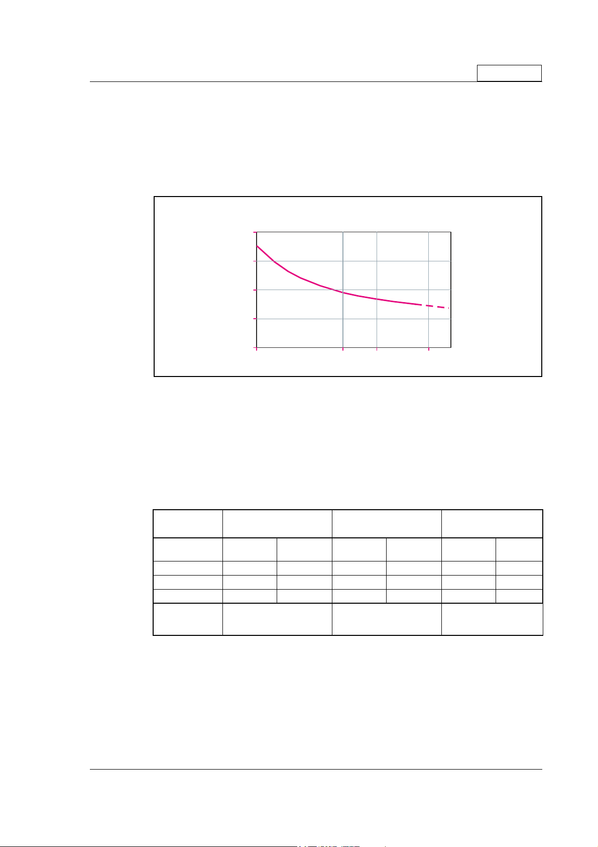
2.1.3 Control Voltage (CVI) - only MIS23x motors
The control voltage should be in the range 12-28VDC and is used to supply the microprocessor circuit, internal functions in general and the user output driver (O1-8).
To ensure that position and parameters are maintained after an emergency stop, the
control voltage should be maintained under a stop situation where the P+ (main power)
is disconnected.
Warning: Control voltage higher than 30VDC will damage the controller.
ontrol circuit supply current (CVI) versus voltage
mADC
200
150
100
50
Only MIS23x
0
10 20
TT2325-01GB
24
30
VD
2.1.4 Power Supply Grounding
It is recommended that the housing is connected to ground or common 0 VDC. The
overall earthing of the system must be done at a central point close to the power supply.
2.1.5 Dimensioning power supply and fuse - only MIS23x motors
The power supply must be dimensioned according to the actual motor size.
The size of the pre-fuse also depends on the actual model of the MIS motor.
Use the following table to select the power supply and fuse ratings.
Desired
voltage
-
12VDC 20W T4A 40W T6.3A 60W T10A
24VDC 40W T4A 80W T6.3A 160W T10A
48VDC 80W T4A 160W T6.3A 320W T10A
Recommended
power supply
Supply
rating
PSU24-075
PSU48-240
PSU40-4
MIS231 MIS232 MIS234
Fuse size Supply
rating
PSU24-240
PSU48-240
PSU40-4
Fuse size Supply
rating
PSU24-240
PSU48-240
PSU40-4
Fuse size
See also the appendix which shows the standard power supplies that JVL offers.
2.1.6 General power supply description
The supply voltage can be chosen in the range 12VDC to 48VDC. However the maximum torque is based on 48VDC. A lower voltage will decrease the speed/torque performance, and in general it is not recommended to run the motor at more than 300RPM if
for example 24VDC is used as supply.
JVL Industri Elektronik A/S - User Manual - Integrated Stepper Motors MIS23x, 34x, 43x 13

2.1 Power Supply
Power supply connections to a MAC140 or a QuickStep motor
Only MIS23x
Make sure that all
involved units are
connected to the same
potential
Power supply
+12-48VDC
MAC140 Motor
with MAC00-B1,
B2 or B4
Power
Supply
Control voltage
Only MAC50-141 with
B2 or B4 (Optional)
P+
P-
O+
MIS23x QuickStep motor or
SMC75 Controller
Power
Supply
Control
Voltage
P+
P-
CVI
GND
(control voltage)
+12-28VDC
(Bus voltage)
Allways use shielded cables.
The screen must be connected
to common ground at
the power supply
2.1.7 Select Your Power Supply - only MIS23x motors
We recommend the use of 48VDC or the highest possible voltage to supply the motor.
As seen in the chart below, it is clear that the torque below 100 RPM is independent of
supply voltage. But above 300-500 RPM, the torque at 24VDC is half compared to the
torque at 48VDC.
Additionally, higher voltage gives better current and filter regulation and thereby better
performance. If there is a tendency for motor resonance, a lower supply voltage can be
a solution to the problem.
TT2220GB
14 JVL Industri Elektronik A/S - User Manual - Integrated Stepper Motors MIS23x, 34x, 43x

2.1 Power Supply
2.1.8 Control Voltage (CVI) - only MIS34x motors
The control voltage should be in the range 12-28VDC and is used to supply the microprocessor circuit, internal functions in general and the user output driver (O1-8).
To ensure that position and parameters are maintained after an emergency stop, the
control voltage should be maintained under a stop situation where the P+ (main power)
is disconnected.
Warning: Control voltage higher than 30VDC will damage the controller.
2.1.9 Power Supply Grounding
It is recommended that the housing is connected to ground or common 0 VDC. The
overall earthing of the system must be done at a central point close to the power supply.
2.1.10 Dimensioning power supply and fuse - only MIS34x motors
The power supply must be dimensioned according to the actual motor size.
The size of the pre-fuse also depends on the actual model of the MIS motor.
Use the following table to select the power supply and fuse ratings.
Only MIS34x
Desired
MIS340 MIS341 MIS342
voltage
-
24VDC 120W T6.3A 200W T6.3A 250W T10A
48VDC 240W T6.3A 350W T6.3A 500W T10A
80VDC 450W T6.3A 600W T6.3A 700W T10A
Recommended
power supply
Supply
rating
PSU24-240
PSU48-240
PSU80-4
Fuse size Supply
Please notice that the specified wattage values are worst case values at maximum torque.
See also the appendix which shows the standard power supplies that JVL offers.
2.1.11 General power supply description
The supply voltage at the main power (P+ terminals) can be chosen in the range 12VDC
to 80VDC (nominal). However the maximum performance is based on a 80V DC supply.
A lower voltage will decrease the speed/torque performance.
See also the torque curves in the appendix Section 13.4, page 280.
rating
PSU24-240
PSU48-240
PSU80-4
Fuse size Supply
rating
PSU24-240
PSU80-4
Fuse size
JVL Industri Elektronik A/S - User Manual - Integrated Stepper Motors MIS23x, 34x, 43x 15

2.2 Inputs
2.2.1 Inputs
The Quickstep motors has 8 inputs/outputs (IO’s) that each can be set individually to input, output or analogue input 0-5VDC via MacTalk or software commands. See Using
MacTalk, page 57, for setup.
This means for example that it is possible to have 4 inputs, 3 outputs and one analogue
input.
Please notice: The number of available IO terminals available may vary de-
!
Input/output functional diagram:
pending at which motor type you are using. Please the chapter Connector overview for the MIS23x, page 33 or Connector overview for the MIS34x, page 35
Internal µ-Processor
Digital output
Digital input
Analog input
TT2160-02GB
2.2.2 General Input features
• Inputs are TTL to 28VDC compliant.
• Over-current protection and thermal shut-down.
•10 kOhm input resistance.
• No galvanic isolation.
• Zero search input can be selected to any input 1 to 8.
• Digital filter can be enabled for each input selectable from 0 to 100ms. If disabled, the
response time is 100µs.
• Analogue filter can be selected for all analogue inputs.
Overcurrent protection
+5V
4k7
1nF
<1 Ohm
CVI
IO1 to IO8
10kOhm
Only MIS23x:
• High speed incremental counter on Input 1 and Input 2.
• High speed Pulse/direction on Input 1 and Input 2 for gear mode.
• Positive and negative limit can be selected to any input 1 to 8 (only MIS23x)
16 JVL Industri Elektronik A/S - User Manual - Integrated Stepper Motors MIS23x, 34x, 43x

2.2 Inputs
Note that End-of-travel inputs,
I1-8 and HM share a
Se le ct exte rn a l
or inte rn a l p o w e r
sup p ly to s e n s o rs
or s imila r
comm on ground ( GN D).
All three ground terminals ( GND and P-)
are connected together.
PNP Output
Power Supply
+5-30VDC
This d iagra m is u s ed if a n NPN outp u t is c o nnec t e d
Power Supply
+5-30VDC
2.2.3 General
The Controller is equipped with a total of 8 digital inputs. Each input can be used for a
variety of purposes depending on the actual application. Each of the inputs can be detect
ed from the actual program that has been downloaded to the Controller or via serial
commands.
The Inputs are not optically isolated from other Controller circuitry. All of the Inputs
have a common ground terminal, denoted GND. Each Input can operate with voltages
in the range 5 to 30VDC. Note that the Inputs should normally be connected to a PNP
output since a positive current must be applied for an input to be activated.
Note that CVO is available as CVI on the I/O connectors. This provides the facility that
local sensors can be supplied directly from the controller.
+
Inductive
sensor
or similar
Inductive
sensor
+
or similar
NPN Output
R
CVO
User Inputs
cçê=~Åíì~ä=ÅçååÉÅíáçåë=
cçê=~Åíì~ä=ÅçååÉÅíáçåë=
ëÉÉ=Çê~ïáåÖ=é~ÖÉ=NN
ëÉÉ=Çê~ïáåÖ=é~ÖÉ=NN
TT2161GB
-
2.2.4 Connection of NPN Output
If an Input is connected to an NPN output, a Pull-Up resistor must be connected between the Input and the + supply. See the illustration above.
The value of the resistance used depends on the supply voltage. The following resistances
are recommended:
Supply Voltage Recommended Resistance R
5-12VDC 1kOhm / 0.25W
12-18VDC 2.2kOhm / 0.25W
18-24VDC 3.3kOhm / 0.25W
24-30VDC 4.7kOhm / 0.25W
JVL Industri Elektronik A/S - User Manual - Integrated Stepper Motors MIS23x, 34x, 43x 17

2.2 Inputs
2.2.5 Digital inputs - features.
All of the eight I/O signals can be used as digital inputs. The sampled and possibly filtered
value of each input is stored in the Input’s register (reg. 18). Unlike the analogue inputs,
there is only one value for each digital input, so it must be configured to be either unfil
tered or filtered.
Unfiltered (high-speed) digital inputs are sampled every 100 µS (micro-seconds).
Filtered digital inputs are sampled every milli-second, and the filter value can be set in the
range 1 to100 mS, so the filtered input must be sampled to have the same logical value
for that number of samples in a row. Once an input has changed state after passing the
filtering, it will again take the same number of samples of the opposite logical level to
change it back. For example, if the filter is set to 5 mS and the start value is 0 (zero), the
input will remain at zero until three samples in succession have been read as 1 (one). If
the signal immediately drops down to 0 again, it will take three samples of zero in suc
cession before the register bit gets set to zero.
Note that filtering of the digital inputs does load the micro-controller, so if filtering of the
digital inputs is not needed, ALL the inputs can be selected as high-speed to reduce the
load.
-
-
18 JVL Industri Elektronik A/S - User Manual - Integrated Stepper Motors MIS23x, 34x, 43x

2.3 Analogue Inputs
8
2.3.1 General
The 0-5V Analogue Inputs are used for example when the Controller is operated as a
stand-alone unit. In this kind of application it can be an advantage to use a potentiometer,
joystick or other device for adjusting speed, position, acceleration, etc.
In these modes of operation, the motor is controlled to produce a velocity or position,
etc., which is determined by, and proportional to, the voltage applied to the Analogue
Input.
The Analogue Inputs share a common internal supply with the GND and P- terminal and
are not optically isolated from all other inputs and outputs. The Analogue Inputs are pro
tected against voltage overload up to 30V peak and have a built-in filter which removes
input signal noise. See
Always use shielded cable to connect the source used to control an Analogue Input since
the motor, etc., can easily interfere with the analogue signal and cause instability.
The Controller is equipped with 8 analogue-to-digital converters (ADC) which convert
the detected analogue signal level. The ADCs have a resolution of 10bit.
In order to use the Analogue Inputs as 0-20 mA inputs, a 250 Ω, 1% resistor must be
connected between IO 1-8 and GND.
PC-card or
Poten tio m e ter
Ground
0-5V Out
TT2164GB
Note ! : screen only
connected to signal source.
Analogue inputs
0-5VDC Input
Screen
Analogue input filters, page 20.
-
0-20mA
250 Ohm
1%
0.25W
TT2186GB
IO 1 -
P-
Please notice: The number of available IO terminals available may vary depending at which motor type you are using. Please the chapter Connector over-
!
view for the MIS23x, page 33 or Connector overview for the MIS34x, page 35
JVL Industri Elektronik A/S - User Manual - Integrated Stepper Motors MIS23x, 34x, 43x 19

2.3 Analogue Inputs
2.3.2 Analogue input filters
The Intelligent MIS motors have 8 general-purpose I/Os, that can be used as both digital
inputs, digital outputs and analogue inputs. When an I/O is configured to be an input, it
simultaneously has both a digital value (high or low) and an analogue value in the range
0.00 to 5.00 Volts. Input voltages higher than 5.0 Volts will be internally limited and read
as 5.00 Volts.
The inputs use a resolution of 10 bits, which means that in the raw motor units a value
of 5.00 Volts reads out as the value 1023. This gives a resolution of 5.00/1023 = 4.8876
mV per count.
The eight values from the analogue inputs are maintained by the SMC75 firmware in the
registers 89...96 as raw, unfiltered values with the fastest possible update frequency, and
additionally in the registers 81...88 as filtered values. The firmware does not use any of
the values for dedicated functions. It is always up to the program in the motor to read
and use the values.
The analogue filtered values are typically used to suppress general noise or to define how
quickly the input value is allowed to change, or in some cases to limit the input voltage
range. A typical example is an analogue input that is connected to a manually controlled
potentiometer, so an operator can regulate the speed of the machine by turning a knob.
In many environments, this setup is subject to noise, which could make the motor run
unevenly, and cause too sharp accelerations or decelerations when the knob is turned.
The filter functions supported in the SMC75 firmware always use three different steps.
Confidence check
First the raw input value is compared to two Confidence limits: Confidence Min and
Confidence Max. If the new value is either smaller than the Confidence Min limit or larger
then the Confidence Max limit, it is simply discarded (not used at all), and the value in its
associated register is unchanged. This is done to eliminate noise spikes. Confidence limits
can only be used if not all of the measurement range is used. Values of 0 for Confidence
Min and 1023 for Confidence Max will effectively disable the confidence limits.
Slope limitation
After a new sample has passed the Confidence limit checks, its value is compared with
the last filtered value in its associated register. If the difference between the old and the
new value is larger than the Max Slope Limit, the new value is modified to be exactly the
old value plus or minus the Max Slope Limit. This limits the speed of change on the signal.
Since the samples come at fixed intervals of 10 mS, it is easy to determine the number of
Volts per millisecond. A value of 1023 will effectively disable slope limitation.
Filtering
After a new sample has both passed the confidence limits checks and has been validated
with respect to the slope limitation, it is combined with the last filtered value by taking a
part of the new sample and a part of the old filtered value, adding them together and
writing the result back to the final destination register – one of the registers 81...88. For
instance a filter value of 14 would take 14/64 of the new sample plus 50/64 of the old
value. A filter of 64 would simply copy the new sample to the rule, thus disabling the fil
tering. This completes the filtering of the analogue inputs.
-
20 JVL Industri Elektronik A/S - User Manual - Integrated Stepper Motors MIS23x, 34x, 43x

2.3 Analogue Inputs
Confidence alarms
If either of the Confidence Min or Confidence Max limits is used, it may be possible that
no new samples are accepted, which means that the filtered value will never change even
though there is a change in the input voltage. For instance, if the Confidence Min limit is
set to 2.0 V, and the actual input voltage is 1.50 V, the filtered value may continue to read
out 0.00 V (or the last value it had before exceeding the confidence limits).
To help troubleshooting in cases like this, each input has a status bit that is set if at least
half of the new samples during the last second lie outside either confidence limit. It is not
possible to see which of the confidence limits is violated. The status bits are updated once
per second.
Slope alarms
If the Max Slope limit is used (by setting its value lower than 1023), it may be possible
that many samples have their value limited. This is not necessarily an error in itself, but
can be a sign of a fault causing a noisy signal, or it can be a sign that the Max Slope limit is
set too low, which can have implications if the analogue voltage is used to control the mo
tor speed, torque, etc.
To help troubleshooting in cases like this, each input has a status bit that is set if at least
half of the new samples during the last second were limited by the Max Slope setting. The
status bits are updated once per second.
Example of analogue input filter operation:
Note that even though the examples use units rather than Volts, decimal values are used,
since the motor uses a much higher resolution internally to store the units.
Also note that as long as the slope limitation is in effect, the result will keep a constant
slope even when using a filter. When the slope limitation is no longer in effect, the filter
will cause the value to approach the final result more slowly as it approaches the result.
-
Confidence Min = 0, Confidence Max = 500, Max Slope = 10, Filter = 8, Old filtered
value = 0.
Sample 1 = 100 Confidence OK, slope limit to 0 + 10 = 10,
result = 10*(8/64)+0*(56/64) = 1.25 units.
Sample 2 = 100 Confidence OK, slope limit to 1.25 + 10 = 11.25,
result = 11.25*(8/64)+1.25*(56/64) = 2.5 units.
Sample 3 = 100 Confidence OK, slope limit to 2.5 + 10 = 12.5,
result = 12.5*(8/64)+2.5*(56/64) = 3.75 units.
Sample 4 = 800 Confidence error, keep old value, result = 3.75 units.
…and so on until the result gets ~= 95.0 units…
Sample 78 = 100 Confidence OK, no slope limitation needed,
result = 100*(8/64)+95*(56/64) = 95.625 units.
Sample 79 = 100 Confidence OK, no slope limitation needed,
result = 100*(8/64)+95.625*(56/64) ~= 96.171875 units.
Sample 80 = 100 Confidence OK, no slope limitation needed,
result = 100*(8/64)+96.171875*(56/64) ~= 96.65 units.
Sample 81 = 100 Confidence OK, no slope limitation needed,
result = 100*(8/64)+96.65*(56/64) ~= 97.07 units.
JVL Industri Elektronik A/S - User Manual - Integrated Stepper Motors MIS23x, 34x, 43x 21

2.3 Analogue Inputs
Sample 82 = 100 Confidence OK, no slope limitation needed,
result = 100*(8/64)+97.07*(56/64) ~= 97.44 units.
Sample 83 = 100 Confidence OK, no slope limitation needed,
result = 100*(8/64)+97.44*(56/64) ~= 97.76 units.
... The following samples produce the following results ending up with the input value
(100.0).
98.04, 98.28, 98.49, 98.68, 98.85, 99.00, 99.12, 99.23, 99.33, 99.41, 99.48, 99.55, 99.60,
99.65, 99.70, 99.74, 99.77, 99.80, 99.82, 99.84, 99.86, 99.88, 99.90, 99.91, 99.92, 99.93,
99.94, 99.95, 99.95, 99.96, 99.96, 99.97, 99.97, 99.98, 99.98, 99.98, 99.98, 99.99, 99.99,
99.99, …….100.0
22 JVL Industri Elektronik A/S - User Manual - Integrated Stepper Motors MIS23x, 34x, 43x

2.4 User Outputs
8
312
)
0
2.4.1 User outputs
The MIS motors has 8 inputs/outputs (IO’s) that each can be set individually to input, output or analogue input 0-5V via MacTalk or software commands.This means that it for example is possible to have 4 inputs, 3 outputs and one analogue input.
Please notice: The number of available IO terminals available may vary depending at which motor type you are using. Please the chapter Connector over-
!
view for the MIS23x, page 33 or Connector overview for the MIS34x, page 35
Input/output functional diagram:
Internal µ-Processor
Overcurrent protection
<1 Ohm
CVI
Digital output
+5V
4k7
TT2160-02GB
Digital input
Analog input
1nF
10kOhm
IO1 to IO
• Outputs are Source (PNP) outputs and 5-28VDC compliant
• No galvanic isolation
• Short-circuit to ground protected that shuts down all outputs and sets Error bit in
software
• In Position and Error signal can be selected to be on any outputs 1 to 8
• Optional Encoder outputs
• 75 to 350 mA output current that depends on number of outputs activated and on
duty cycle. (See diagram)
• Internal ground clamp diodes
Allowable output current as a function of duty cycle
Number of output s conducting si multaneousl y
273
234
)
A
m
(
t
195
n
e
r
r
u
C
156
r
o
t
c
e
l
l
117
o
C
78
39
0
0
10
8
20
30
JVL Industri Elektronik A/S - User Manual - Integrated Stepper Motors MIS23x, 34x, 43x 23
76
40
Duty Cycle (%
5
4
3
50
70
60
80
90
TT2180GB
2
10

2.4 User Outputs
C
Output circuit (PNP output)
O8
O7
O6
O5
O4
O3
O2
O1
O-
CVI
Load
TT2165GB
NB: For actual SMC75 connections, see Step motor controllers (SMCxx), page 266.
2.4.2 General
The Controller is equipped with a total of 8 digital outputs. Each output can be used for
a variety of purposes depending on the Controller’s basic mode of operation. The Out
puts are not optically isolated from other Controller circuitry. The output circuitry is
powered from the internal power supply CVI. The output circuitry operates with volt
ages in the range 5-28VDC. Each output can supply a continuous current up to 350mA.
The outputs are all source drivers, i.e. if a given output is activated, contact is made be
tween the control voltage (CVI) and the respective output terminal. See above illustration.
2.4.3 Overload of User Outputs
All of the outputs are short-circuit protected, which means that the program and the motor is stopped and the output is automatically disconnected in the event of a short circuit.
The output will first function normally again when the short-circuit has been removed.
User Outputs
Max. 350mA
CVI
+
8-28VD
-
-
-
Note: Do not connect a voltage greater than 30VDC to the CVI terminal as the output
circuitry may be seriously damaged and the unit will require factory repair.
If one or more outputs are short circuited, MacTalk will show Error “Output Driver” and
Bit2 will be set in Err_Bits
24 JVL Industri Elektronik A/S - User Manual - Integrated Stepper Motors MIS23x, 34x, 43x
Section 8.2.26, page 129.

2.5 Serial interfaces overview
2.5.1 Serial interfaces
The Controller has 2 serial interfaces:
• RS485 (A and B) balanced for up to 32 units in multi-axis applications and MODBUS
communication. (Standard)
• CANbus -CANopen DS-301/DSP-402,
• DeviceNet under development
CANbus and RS485 can be used at the same time.
Please notice: The number of available IO terminals available may vary depending at which motor type you are using. Please the chapter Connector over-
!
view for the MIS23x, page 33 or Connector overview for the MIS34x, page 35
JVL Industri Elektronik A/S - User Manual - Integrated Stepper Motors MIS23x, 34x, 43x 25

2.6 RS485 Interface
0
2.6.1 RS485 - General description when using a QuickStep motor
The RS485 interface offers
more noise immune commu
nication compared to a USB
or RS232 interface
. Up to 32
motors can be connected to
the same interface bus.
When connecting the RS485
interface to a central control
ler, the following rules must
be followed:
1 Use twisted pair cable.
2 Use shielded cable.
3 Make sure that the GND is
also connected.
-
RS485 network with 1 x QuickStep, 1 x MAC140 and 1 x MAC80
mounted with MAC00-B1, B2 or B4 modules.
Central
Controller
(for example a PC)
Opto isolation *
**
B
-
A
GND
Screen connected
to GND in each end
Make sure that all
involved units are
connected to the same
potential
Power supply
GND
+12-32VDC
QuickStep motor or
SMC75 Controller
*** Address=1
A
RS485
B
Interface
GND
Power
Supply
Control voltage
P+
P-
CVI
(control voltage)
+12-48VDC
(Bus voltage)
4 Ensure that all units have a
proper connection to safety
ground (earth) in order to
refer to the same potential.
5 The last unit in each end of
the network must be termi
nated with a 120 Ohm resistor between A and B.
6 Ensure that the supply lines
are made individually in or
der to reduce the voltage
drop between the motors.
7Central Controller RS485
interface:
If available, it is strongly recommended a type with optical isolation is used.
The default configuration:
Databits = 8
Baud rate = 19200
Stop bit = 1
Parity = None
ScreenScreen Screen
MAC50-141
Motor
*** Address=2
A
RS485
B
-
-
Interface
GND
Power
Supply
Control voltage
Only MAC50-141 with
B2 or B4 (Optional)
P+
O+
P-
MAC800
Motor
*** Address=3
A
**
RS485
B
Interface
GND
Power
Supply
Up to 32
Motors
* Opto isolation is recommended.
** The last unit in each end of the line must be terminated. The MAC00-B1, B2
and B4 contain this feature. See the individual module descriptions.
The QuickStep motor does not have a resistor built-in, the resistor
has to be mounted externally, for instance in the M12 connector.
*** Each unit connected must be setup with an address via The MacTalk program.
If only one unit is connected no address is needed.
Main supply
P+
P-
Max. 32VDC !
Mains 230VAC
TT2181GB
26 JVL Industri Elektronik A/S - User Manual - Integrated Stepper Motors MIS23x, 34x, 43x

JVL Industri Elektronik A/S - User Manual - Integrated Stepper Motors MIS23x, 34x, 43x 27

2.7 Special Outputs
A
2.7.1 Error Output
Error output can be selected as one of the 8 outputs. This selection is done in MacTalk
or by setting a bit in register Error_Mask,
The Driver’s Error Output enables a PLC or other equipment in a motion control system
to verify that the Driver is functioning correctly.
Under normal operation, the Error Output has a status of logic “1”, but if the Driver is
short-circuited or the temperature exceeds 85 degrees Centigrade, the Output is
switched to logic “0”.
2.7.2 In Position Output
In Position Output can be selected as one of the 8 outputs.
This selection is done in MacTalk or by setting a bit in register 137 (bit 0-7) InPos_Mask,
Section 8.2.73, page 143.
When the motor is running, the output will be inactive. When the motor is at stand-still,
the output will be active.
2.7.3 In Physical Position Output”
In physical position can be selected as one of the 8 outputs.
This selection is done in MacTalk or by setting a bit in register 137 (bit 8 – 15)
InPos_Mask,
Section 8.2.73, page 143.
Section 8.2.74, page 143
This signal is used together with MIS motors with an internal or external encoder for positioning.
This signal can be selected to be continuously updated and will then indicate if the motor
is inside the “In Position Window” all the time.
If continuous update of the “In Physical Position” is not selected and the autocorrection
is used, this signal is changed after a move and when a check has been made of the posi
tion after the “settling time between retries” if the motor is inside the “In Position Window”.
In Physical Position Example
Requested
Pos i t i on
ctual
Pos i t i on
In Position
In Phys.Position:
w. o. update
w. U pda te
IPW=1
IPW=50
IPW=5
Settling time
TT2206GB
-
See also Cable WG1005 for MIS231A1C2N075 and mounted cable on MIS231a1C1N075
(Power Cable), page 30.
28 JVL Industri Elektronik A/S - User Manual - Integrated Stepper Motors MIS23x, 34x, 43x

2.7 Special Outputs
2.7.4 Pulse/Direction Outputs
Any number of the outputs can be configured to follow the pulse and direction signals
used internally in the motor. This can be used for accurate synchronization of two or
more motors.
SMC75
TT2230-02GB
O1-O2
O3-O4
O5-O6
O7-O8
See the register description for registers 108 and 109 in PulseDirMask, page 136 and PulseDirMod, page 136
2.7.5 Encoder Outputs (only from version 2.0)
If the motor is equipped with a built-in encoder, it is possible to obtain the incremental
signal and the index pulse out on the user outputs. Please note that the voltage typically
is 24VDC PNP. Therefore a resistor to ground should be connected.
A 2 channel encoder with 256 pulses/revolution will give a total of1024 pulses/revolution.
SMC75
06
A
Driver
PLC
Motor
N
07
B
S
08
If a magnet is mounted on the rear end of the motor shaft and this is placed in close distance to the SMC75 PCB, a 1023 pulses/rev. incremental A, B, index signal will be available on 3 of the output pins. Encoder position will also be available at an internal register
and can be used in a PLC program.
Index
TT2232GB
Output Encoder designation
06 A
07 B
08 Index
JVL Industri Elektronik A/S - User Manual - Integrated Stepper Motors MIS23x, 34x, 43x 29

2.8 Special Connections
QuickStep motor MIS231A1C1N075.
Motor with 2 cable glands PG12 out of the side for low cost applications where a short
total length is required.
Can also be delivered with 5m cables as MIS231A1C2N075. Option for IP65.
Cable WG0905 for MIS231A1C2N075 and mounted cable on MIS231A1C1HN075
Connector J3
Pin no. Function Colour
1 IO1 White
2 IO2 Brown
3 IO3 Green
4 IO4 Yellow
5 CVO Red
6 A- Grey
7 B+ Pink
8 GND Black
9-10 Not used
Connector J4
Pin no. Function Colour
1 IO5 Blue
2 IO6 Violet
3 IO7 Grey/Pink
4 IO8 Red/Blue
5-10 Not used
Connector J5
Pin no. Function Colour
1-2 Not used
3 CAN_H White/Green
4 CAN_L Brown/Green
5 V+ White/Yellow
6 GND Yellow/Brown
Connector J8
Screen
Cable WG1005 for MIS231A1C2N075 and mounted cable on MIS231a1C1N075 (Power
Cable
)
Connector J2
Pin no. Function Colour
1 P+ Red
2 CVI Blue
3 P-/GND Black/Screen
30 JVL Industri Elektronik A/S - User Manual - Integrated Stepper Motors MIS23x, 34x, 43x

2.9 Handling noise in cables
2.9.1 About noise problems
The MIS family of motors eliminates the traditional problems with noise from long motor
cables that emit noise and feedback cables that are sensitive to noise from external
sources.
However, it is still necessary to be aware of noise problems with communications cables
and the 8 general-purpose inputs and outputs.
Whenever a digital signal changes level quickly, a noise spike is generated, and is transferred to the other wires in the same cable, and to a lesser degree to wires in other cables located close to the cable with the switching signal. A typical example is when a
digital output from the MIS motor changes from low to high to drive a relay. If this digital
output signal is transmitted in a multi-wire cable together with the RS-485 signals, there
is a high risk that the RS-485 signal will be affected to the extent that the communication
will fail, and require software retries.
If communication is used during operation, and operation includes either digital input signals or digital output signals, some precautions must be taken to avoid noise problems.
The following sections describe a number of measures which can be taken to solve noise
problems. In most installations, no special measures will be required, but if noise prob
lems are experienced – and/or must be avoided – it is highly recommended the instructions below are followed.
2.9.2 Use short cables
The shorter a cable is, the less noise problems it will induce. Be sure to keep the cables
as short as possible. Instead of curling up the cables, cut them off at the minimum re
quired length.
-
-
2.9.3 Use separate cables
Avoid running digital signals in the same multi-wire cables as RS-485 communication signals.
On some models of the MIS motors, the same connector contains both RS-485 signals
and I/O signals – typically the I/Os 1-4.
In many applications, far from all inputs and outputs are used. If only up to four I/Os are
required, consider using only I/Os 5-8 which are typically available via another connector
on the motor.
2.9.4 Use filters
If more than 4 I/Os are needed, consider using I/Os 1-4 for inputs and I/Os 5-8 for outputs. It is normally possible to install a hardware filter on the digital input signals before
they enter the cable. With such a (good) filter, noise on the RS-485 signals will not be a
problem.
It is also possible to use filters on the outputs, but it is more difficult. It can be done by
using short cables from the motor to the filters, and then using longer cables from the
filters to the output targets. It may be easier to use a short cable from the motor to a
splitter box, and then split the I/Os in one cable and the RS-485 signals in another cable.
2.9.5 Use termination (resistors) on the RS-485 signals
RS-485 is typically used to connect a single master PC or PLC to one or more motors in
a chain. Both ends of the chain must have a 120 Ohms termination resistor connected
between the A- and B+ signals. There is typically a terminating resistor in the master PC
or PLC, but there is no termination inside the motors. Therefore an external resistor
must be connected at the end of the cable out of the last motor in the chain. If the last
motor has no connection cable, a connector with a resistor soldered between the A- and
B+ pins should be used.
JVL Industri Elektronik A/S - User Manual - Integrated Stepper Motors MIS23x, 34x, 43x 31

2.9 Handling noise in cables
As an alternative, a connector with a short cable can be used with the resistor soldered
between the two wires carrying A- and B+.
Use individually shielded cables.
In some installations, it will be necessary to have RS-485 signals in the same multi-wire
cables as fast-switching digital signals. In addition to keeping cable lengths to a minimum
and using termination resistors, high-quality cables, where each wire is shielded from the
other wires in the cable, should be used. This is typically done using a metal foil wrapped
around each wire. These types of cables are more expensive, but the overall cost and
noise immunity requirements may justify the solution instead of splitting cables.
2.9.6 Use simple shielding
Using cables with only a single shield shared by all the signal wires will also improve noise
problems to some degree, but will not guarantee completely stable operation for mixed
signal cables. If a cable carries only RS-485 or only digital I/O, this simple and inexpensive
form of shielding is recommended.
32 JVL Industri Elektronik A/S - User Manual - Integrated Stepper Motors MIS23x, 34x, 43x

2.10 How to connect MIS23x
e
2.10.1 Connector overview for the MIS23x
Only MIS23x
# MIS23xAz yy75
RS485 serial communicati on
and few local I/O.
MIS23xAz yy75
RS485 serial communicati on in
network. Up to 32 MAC and QuickStep
on the same network . Many local I /O.
I/O5-8
PWR: RS485: CAN: I/O1-4: I/O5-8: SSI:
5 pin male 5 pin female 5 pin male 8 pin female 8pin female 8 pin mal
PWR
I/O1-4
RS485
PWR
I/O1-4
RS485
M2
M5
RS485
TT2259GB
MIS23xAz yy75
RS485 serial communicat ion in
network. Up to 32 MAC and QuickStep
on the same network. Few local I/ O.
MIS 23x Az y y75
MIS 23x Az y y75
RS485 and CANopen/Devicenet
operati on. Many local IO.
CAN
PWR
I/O1-4
RS485
PWR
I/O1-4
RS485
M3
RS485
M6
M7
I/O5-8
# MIS23xAz yy75
RS485 serial communicat ion
and many local I/O.
MIS23xAz yy75
RS485 and SSI encoder Few local I/O.
SSI
PWR
I/O1-4
RS485
PWR
I/O1-4
RS485
M4
I/O5-8
M9
RS485
Versions with positioning and speed control
Quick Step M12
Connector
overview
#MIS23xAzM2yy75 X X RS485, 4IO
MIS23xAzM3yy75 X X X 2xRS485, 4IO
#MIS23xAzM4yy75 X X X RS485, 8IO
MIS23xAzM5yy75 X X X X 2xRS485, 8IO
MIS23xAzM6yy75
MIS23xAzM7yy75
MIS23xAzM9yy75 X X X X SSI, 6IO
M12 Pin 1 P+ (12-
M12 Pin 2 P+ (12-
M12 Pin 3 P- (GND) IO3 IO7 B+ (RS485) CAN_GND A+ (Clock+)
M12 Pin 4 CVI+ (12-
M12 Pin 5 P- (GND) B+ (RS485) Not used GND CAN_L B- (Data in-)
M12 Pin 6 - A- (RS485) Not used - - B+ (Data in+)
M12 Pin 7 - IO4 IO8 - - A- (Clock-)
M12 Pin 8 - CVO+ (Out) CVO+ (Out) - - CVO+ (Out)
M12 connector
solder terminals
M12 cables 5m. WI1000-
Power
Male 5pin
IO1-4
RS485
Female 8pin
IO5-8
Female 8pin
RS485
Female 5pin
CANopen/
DeviceNet
Male 5pin
SSI Encoder
Male 8pin
X X X X
X X X X
48VDC) IO1 IO5 B+ (RS485) CAN_SHLD
48VDC IO2 IO6 A- (RS485) CAN_V+
IO5 Zero
setting
IO6 Counting
Direction
28VDC) GND IO- GND IO- A- (RS485) CAN_H GND
WI1008M12F5SS1
M12F5T05N
WI1008M12M8SS1
WI1000M12M8T05N
WI1008M12M8SS1
WI1000M12M8T05N
WI1008M12M5SS1
WI1000M12M5T05N
WI1008M12F5SS1
WI1006M12F5S05R
WI1008M12M8SSI
WI1000M12M8T05N
Function
CANopen,
RS485, 8IO
DeviceNet,
RS485, 8IO
#: Only >50pcs order. x : 1~1Nm, 2~1.6Nm, 3~2.5Nm.
z : 1~6.35mm shaft, 3~10.0mm shaft (only if x=3)
yy : NO~No encoder. H2~built-in encoder
JVL Industri Elektronik A/S - User Manual - Integrated Stepper Motors MIS23x, 34x, 43x 33

2.10 How to connect MIS23x
2.10.2 M12 connectors
M12 connectors layout and pin locations.
Only MIS23x
1
4
1
7
6
2
5
3
2
8
3
4
5
2
3
2
3
4
1
5
4
1
7
6
5
TT2143GB
34 JVL Industri Elektronik A/S - User Manual - Integrated Stepper Motors MIS23x, 34x, 43x

2.11 How to connect MIS34x
4
2.11.1 Connector overview for the MIS34x
QUICKSTEP
Connector
Overview
Connector ID
MIS34xCyyQ5zz85
(8IOA) Prefered type
MIS34xCyyP6zz85
(CAN-open)
MIS34xCyyQ9zz85
(SSI input)
MIS34xCyyExzz85
(Ethernet)
MIS34xCyyFBzz85
(Bluetooth)
MIS34xCyyFPzz85
(Profibus)
M12 Pin1
M12 Pin2
M12 Pin3
M12 Pin4
M12 Pin5
M12 Pin6
M12 Pin7
M12 Pin8
M12 Pin9
M12 Pin10
M12 Pin11
M12 Pin12
M12 Pin13
M12 Pin14
M12 Pin15
M12 Pin16
M12 Pin17
M12 Connector
solder terminals
M12 Cables 5m
Power
Male
5Pin
PWR (CN1) CN4 CN2 CN3 CN2 CN2 & CN3 CN3 CN2 & CN3 CN2 & CN3
P+ (12-80VDC) IO1 B0+ (RS485) IO1 IO1 CAN_SHLD IO5 Zero Set 5VDC TX0_P
P+ (12-80VDC) GND A0- (RS485) IO2 IO2 Unused IO6 CNTDIR A- RX0_P
P- (GND) IO2 B0+ (RS485) IO3 IO3 CAN_GND A+ (Clock+) DGND TX0_N
CVI (12-28VDC) IO3 A0- (RS485) GND GND CAN_H GND B+ RX0_N
P- (GND) B1- (RS422) GND B0-(RS485) B0-(RS485) CAN_L B- (Data In-) SHIELD -
- IO4 - A0+(RS485) A0+(RS485) - B+ (Data In+) - -
- A1- (RS422) - IO4 IO4 - A- (Clock -) - -
- B1+ (RS422) - CVO (out) CVO (out) - CVO (out) - -
- CVO (out) - - - - - - -
- A1+ (RS422) - - - - - - -
- IO5 - - - - - - -
- IO6 - - - - - - -
- IO7 - - - - - - -
- IO8 - - - - - - -
- A0+(RS485) - - - - - - -
- GND - - - - - - -
- B0-(RS485) - - - - - - -
WI1008M12F5SS1
WI1000M12F5T05N
IO1-8,
RS485,MFIO
Female
17Pin
x x x x
x x x
x x x x
x x x
x x x x
x x x
(not available) WI1008-
WI1009M12M17T05N
RS485
Female
5Pin
M12M5SS1
WI1005M12M8V
M5V03N
RS485 +
IO1-4
Female
8Pin
WI1008M12M8SS1
WI1009M12M8V05N
RS485 +
IO1-4
Female
8Pin
WI1008M12M8SS1
WI1009M12M8V05N
CANopen
Female
5Pin
WI1008M12M5SS1
WI1006M12F5
TM5T05N
SSI Encoder
Male 8Pin
WI1008M12F8SS1
WI1000M12F8T05N
Only MIS34x
Profibus
Male 5Pin
WI1028M12F5SS1
WI1026M12-F5S0R
Ethernet
Female
4Pin
(not available)
WI1046M12M4S05R
Connector layout
CN3
TT2323-01GB
CN4
PWR (CN1)
CN2
5 pin Female
1
4
8 pin Female
1
8
7
6
12 pin Female
1
10
9
8
12
7
17 pin Female
1
11
10
16
9
17
8
15
7
pin Female
2
3
2
4
5
2
4
11
5
6
2
12
4
13
5
14
6
2
5
3
5 pin Male
2
3
3
8 pin Male
2
3
3
4
3
1
4
1
5
4
1
8
7
6
5
JVL Industri Elektronik A/S - User Manual - Integrated Stepper Motors MIS23x, 34x, 43x 35

2.11 How to connect MIS34x
)
Only MIS34x
CN2
RS485 IN/OUT
PWR (CN1)
Power input
TT2332-01GB.cdr
2.11.2 MIS34xxxxQ5xxxx connector description.
The MIS34x offers robust M12 connectors which makes it ideal for automation applications. The M12 connectors offer solid mechanical protection and are easy operate.
Following scheme gives the relevant information about each connector and the pins, wire
colours and a short description of the signals available.
The connector layout:
“PWR” (CN1) - Power input. M12 - 5pin male connector
Signal name Description Pin no.
P+ Main supply +12-80VDC. Connect with pin 2 * 1 Brown 1
P+ Main supply +12-80VDC. Connect with pin 1 * 2 White 1
P- Main supply ground. Connect with pin 5 * 3 Blue 1
CVI
P- Main supply ground. Connect with pin 3 * 5 Grey 1
* Note: P+ and P- are each available at 2 terminals. Make sure that both terminals are connected in order
to split the supply current in 2 terminals and thereby avoid an overload of the connector.
Control and user output supply +12-30VDC.
DO NOT connect >30V to this terminal !
CN3
RS485 + I/O
CN4
RS485 + I/O + Backup(optional
JVL Cable
WI1000M12F5TxxN
4 Black 1
Isolation
group
(Continued next page)
36 JVL Industri Elektronik A/S - User Manual - Integrated Stepper Motors MIS23x, 34x, 43x

2.11 How to connect MIS34x
“CN2” - RS485 IN/OUT. M12 - 5pin female connector.
Signal name Description Pin no.
RS485: B+ RS485 interface. Leave open if unused 1 Brown 1
RS485: A- RS485 interface. Leave open if unused 2 White 1
RS485: B+ RS485 interface. Leave open if unused 3 Blue 1
RS485: A- RS485 interface. Leave open if unused 4 Black 1
GND Ground intended to be used toghether with the
other signals in this connector
“CN3” - RS485 + I/O connector - M12 - 8pin female connector.
Signal name Description Pin no.
IO1 I/O channel 1. Can be used as input or output 1 White 1
IO2 I/O channel 2. Can be used as input or output 2 Brown 1
IO3 I/O channel 3. Can be used as input or output 3 Green 1
GND
Ground intended to be used toghether with the
other signals in this connector
RS485: B+ RS485 interface. Leave open if unused 5 Grey 1
RS485: A- RS485 interface. Leave open if unused 6 Pink 1
IO4 I/O channel 4. Can be used as input or output 7 Blue 1
CVO Supply output. Connected internally to the CVI
terminal in the PWR connector.
DO NOT connect >30V to this terminal !
USB interface. Supply input 5VDC nominal
“CN4” - RS485 + I/O + Backup(option) connector - M12 - 17pin female connector
Signal name Description Pin no.
IO1 I/O channel 1. Can be used as input or output 1 Brown 1
GND
IO2 I/O channel 2. Can be used as input or output 3 White 1
IO3 I/O channel 3. Can be used as input or output 4 Green 1
B1- RS422 I/O terminal B- 5 Pink 1
IO4 I/O channel 4. Can be used as input or output 6 Yellow 1
A1- RS422 I/O terminal A- 7 Black 1
B1+ RS422 I/O terminal B+ 8 Grey 1
CVO Supply output. Connected internally to the CVI termi-
A1+ RS422 I/O terminal A+ 10 Violet 1
IO5 I/O channel 5. Can be used as input or output 11 Grey/pink 1
IO6 I/O channel 6. Can be used as input or output 12 Red/blue 1
IO7 I/O channel 7. Can be used as input or output 13 White/Green 1
IO8 I/O channel 8. Can be used as input or output 14 Brown/Green 1
RS485: B+ RS485 interface. Leave open if unused 15 White/Yellow 1
GND/
EXTBACKUP
RS485: A- RS485 interface. Leave open if unused 17 White/grey 1
* Note: Isolation group indicate which terminals/circuits that a galvanic connected to each other. In other
words group 1, 2, 3 and 4 are all fully independantly isolated from each other. Group 1 correspond to the
housing of the motor which may also be connected to earth via the DC or AC input supply.
Ground intended to be used toghether with the other
signals in this connector
nal in the PWR connector.
DO NOT connect >30V to this terminal !
Only for motors installed with the H3 option (absolute
multiturn encoder). This terminal can be connected to
an external supply.
Connect to ground if not used.
5 Grey 1
4 Yellow 1
8 Red 1
2 Blue 1
9 Red 1
16 Yellow/brown 1
JVL Cable
WI1000-M12
M5TxxN
JVL Cable
WI1000-M12
M8TxxN
JVL Cable
WI1009M12
M17TxxN
Only MIS34x
Isolation
group
(See note)
Isolation
group
(See note)
Isolation
group
(see note)
JVL Industri Elektronik A/S - User Manual - Integrated Stepper Motors MIS23x, 34x, 43x 37

2.11 How to connect MIS34x
2.11.3 Cables for the MIS34xxxxQ5xxxx
The following cables equipped with M12 connector can be supplied by JVL.
MIS34x Connectors Description JVL Order no. Picture
Only MIS34x
“PWR”
5pin
Male
“CN2”
5pin
Female
X
X
X
“CN3”
8pin
Female
X
X
X
“CN4”
17pin
Female
RS485 Interface cable. Connects
directly from the MIS motor to a
RS485 comport.
Length: 5m (197 inch)
RS485 Interface cable. Connects
directly from the MIS motor to a
RS485 comport.
Length: 5m (197 inch)
USB to RS485 Converter. To be
used if no RS485 COM port is avail
able.
Cable (Ø5.5mm) with M12 male
5-pin connector loose wire ends
0.35mm² (22AWG) and foil screen.
Length: 5m (197 inch)
Same as above but 20m (787 inch)
Cable with M12 male 8-pin connector loose wire ends 0.35mm²
(22AWG) and screen.
Same as above but 20m (787 inch)
RS485-M12-1-5-5
RS485-M12-1-5-8
-
RS485-USB-ATC-820
WI1000-M12M5T05N
WI1000-M12M5T20N
WI1000-M12M8T05N
WI1000-M12M8T20N
TT2333-01GB
Cable with M12 male 17-pin
connector loose wire ends
X
0.22mm² (24AWG) and screen.
Length: 5m (197 inch)
Same as above but 20m (787 inch)
X
Junction box for splitting the 17 pin I/
O connector into 4 independant con
nectors. Include also 9 LED’s for
X
monito-ring the I/O status and communication.
Cable length: 0,5m (20 inch)
WI1009-M12M17S05N
WI1009-M12M17S20N
PA0190
-
Protection caps. Optional if connector is not used to protect from dust / liquids.
X X X
X
IP67 protection cap for M12
female connector.
IP67 protection cap for M12
male connector.
WI1000-M12FCAP1
WI1000-M12MCAP1
36.0mm
[1.42 inch]
54.0mm
[2.126 inch]
= Mounting holes
0
5.0mm
[0.197inch]
2 x
Ø4x8mm
[Ø0.16x0.32inch]
2 x
Ø4/8mm
[Ø0.16/0.32inch]
77.0mm
[3.031inch]
112.0mm
[4.409inch]
118.0mm
TT3088-01GB
[4.646inch]
38 JVL Industri Elektronik A/S - User Manual - Integrated Stepper Motors MIS23x, 34x, 43x

2.11 How to connect MIS34x
Only MIS34x
CN2
RS485 + I/O
WR (CN1)
ower input
TT2348-01GB
2.11.4 MIS34xxxxQ9xxxx connector description.
The MIS34x offers robust M12 connectors which makes it ideal for automation applications. The M12 connectors offer solid mechanical protection and are easy to operate.
The following scheme gives the relevant information about each connector and the pins,
wire colours and a short description of the signals available.
The connector layout:
“PWR” (CN1) - Power input. M12 - 5pin male connector
Signal name Description Pin no.
P+ Main supply +12-80VDC. Connect with pin 2 * 1 Brown 1
P+ Main supply +12-80VDC. Connect with pin 1 * 2 White 1
P- Main supply ground. Connect with pin 5 * 3 Blue 1
CVI
P- Main supply ground. Connect with pin 3 * 5 Grey 1
* Note: P+ and P- are each available at 2 terminals. Make sure that both terminals are connected in order
to split the supply current in 2 terminals and thereby avoid an overload of the connector.
Control and user output supply +12-30VDC.
DO NOT connect >30V to this terminal !
CN3
RS485 (SSI etc.) + I/O
CN4
RS485 + I/O +
Backup(optional)
JVL Cable
WI1000M12F5TxxN
4 Black 1
Isolation
group
(Continued next page)
JVL Industri Elektronik A/S - User Manual - Integrated Stepper Motors MIS23x, 34x, 43x 39

2.11 How to connect MIS34x
“CN2” - RS485 + I/O connector - M12 - 8pin female connector.
Signal name Description Pin no.
IO1 I/O channel 1. Can be used as input or output 1 White 1
IO2 I/O channel 2. Can be used as input or output 2 Brown 1
IO3 I/O channel 3. Can be used as input or output 3 Green 1
GND Ground intended to be used toghether with the
other signals in this connector
RS485: B+ RS485 interface. Leave open if unused 5 Grey 1
RS485: A- RS485 interface. Leave open if unused 6 Pink 1
IO4 I/O channel 4. Can be used as input or output 7 Blue 1
CVO Supply output. Connected internally to the CVI
terminal in the PWR connector.
“CN3” - RS485 (SSI etc.) + I/O. M12 - 8pin Male connector.
Signal name Description Pin no.
IO5 Used for zero set. Leave open if unused 1 White 1
IO6 Counting direction. Leave open if unused 2 Brown 1
RS485: A+ Clock +. Leave open if unused 3 Green 1
GND Signal ground. Leave open if unused 4 Yellow 1
RS485: B- Data in -. Leave open if unused 5 Grey 1
RS485: B+ Data in +. Leave open if unused 6 Pink 1
RS485: A- Clock -. Leave open if unused 7 Blue 1
CVO Supply output. Connected internally to the CVI
terminal in the PWR connector.
“CN4” - RS485 + I/O + Backup(option) connector - M12 - 17pin female connector
Signal name Description Pin no.
IO1 I/O channel 1. Can be used as input or output 1 Brown 1
GND
IO2 I/O channel 2. Can be used as input or output 3 White 1
IO3 I/O channel 3. Can be used as input or output 4 Green 1
B1- RS422 I/O terminal B- 5 Pink 1
IO4 I/O channel 4. Can be used as input or output 6 Yellow 1
A1- RS422 I/O terminal A- 7 Black 1
B1+ RS422 I/O terminal B+ 8 Grey 1
CVO Supply output. Connected internally to the CVI termi-
A1+ RS422 I/O terminal A+ 10 Violet 1
IO5 I/O channel 5. Can be used as input or output 11 Grey/pink 1
IO6 I/O channel 6. Can be used as input or output 12 Red/blue 1
IO7 I/O channel 7. Can be used as input or output 13 White/Green 1
IO8 I/O channel 8. Can be used as input or output 14 Brown/Green 1
RS485: B+ RS485 interface. Leave open if unused 15 White/Yellow 1
GND/
EXTBACKUP
RS485: A- RS485 interface. Leave open if unused 17 White/grey 1
* Note: Isolation group indicate which terminals/circuits that a galvanic connected to each other. In other
words group 1, 2, 3 and 4 are all fully independantly isolated from each other. Group 1 correspond to the
housing of the motor which may also be connected to earth via the DC or AC input supply.
Ground intended to be used toghether with the other
signals in this connector
nal in the PWR connector.
Only for motors installed with the H3 option (absolute
multiturn encoder). This terminal can be connected to
an external supply. Connect to ground if not used.
4 Yellow 1
8 Red 1
8 Red 1
2 Blue 1
9 Red 1
16 Yellow/brown 1
JVL Cable
WI1000-M12
M8TxxN
JVL Cable
WI1000-M12
F8TxxN
JVL Cable
WI1009M12
M17TxxN
Only MIS34x
Isolation
group
(See note)
Isolation
group
(See note)
Isolation
group
(see note)
40 JVL Industri Elektronik A/S - User Manual - Integrated Stepper Motors MIS23x, 34x, 43x
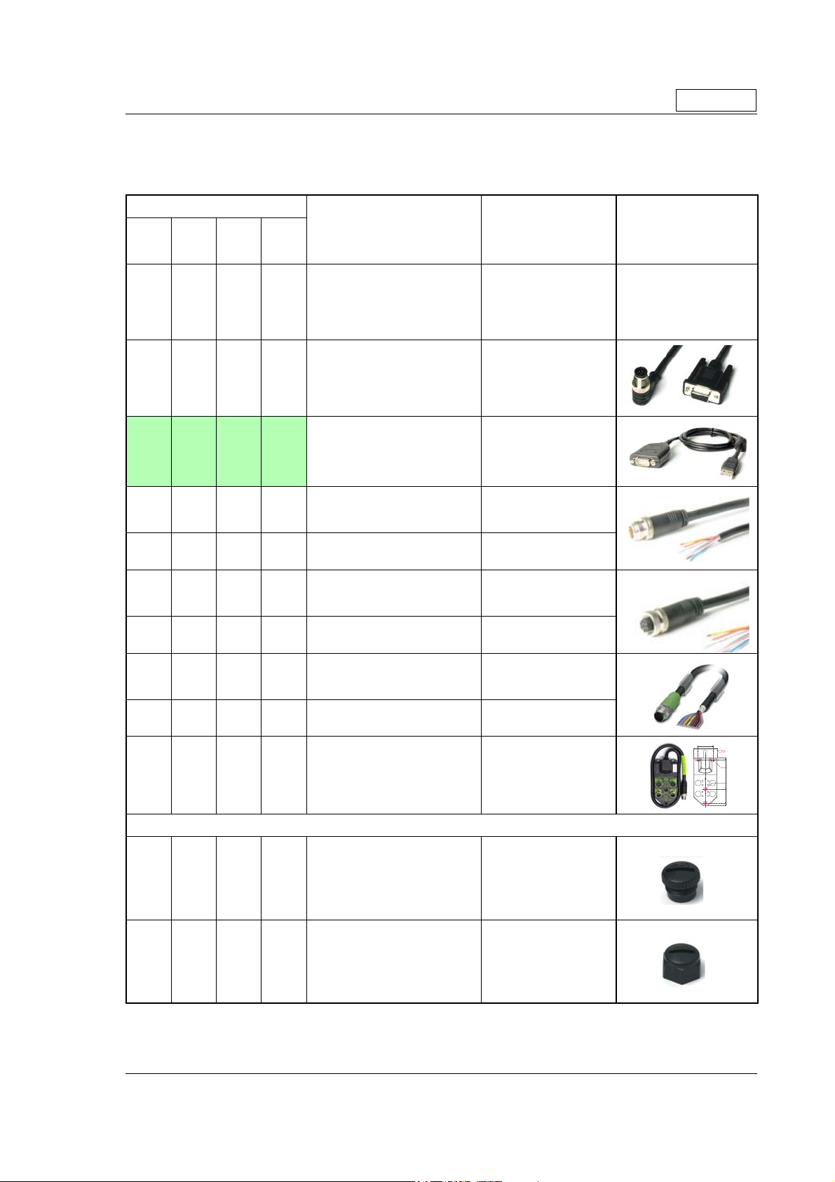
2.11 How to connect MIS34x
2.11.5 Cables for the MIS34xxxxQ9xxxx
The following cables equipped with M12 connector can be supplied by JVL.
MIS34x Connectors Description JVL Order no. Picture
Only MIS34x
“PWR”
5pin
Male
X
“CN2”
8pin
Female
X
(x)
X
X
“CN3”
8pin
Male
X
X
“CN4”
17pin
Female
Cable (Ø5.5mm) with M12 female
5-pin connector loose wire ends
0.35mm² (22AWG) and foil screen.
Length: 5m (197 inch)
RS485 Interface cable. Connects
directly from the MIS motor to a
RS485 comport.
Length: 5m (197 inch)
USB to RS485 Converter. To be
used if no RS485 COM port is avail
able. Use also RS485-M12-1-5-8
Cable (Ø5.5mm) with M12 male
8-pin connector loose wire ends
0.35mm² (22AWG) and foil screen.
Length: 5m (197 inch)
Same as above but 20m (787 inch)
Cable with M12 female 8-pin
connector loose wire ends
0.22mm² (24AWG) and screen.
Length: 5m (197 inch)
Same as above but 20m (787 inch)
WI1000-M12F5T05N
RS485-M12-1-5-8
-
RS485-USB-ATC-820
WI1000-M12M8T05N
WI1000-M12M8T20N
WI1000-M12F8T05N
WI1000-M12F8T20N
TT2333-01GB
Cable with M12 male 17-pin
connector loose wire ends
X
0.22mm² (24AWG) and screen.
Length: 5m (197 inch)
Same as above but 20m (787 inch)
X
Junction box for splitting the 17 pin I/
O connector into 4 independant connectors. Include also 9 LED’s for
X
monito-ring the I/O status and com
munication.
Cable length: 0,5m (20 inch)
WI1009-M12M17S05N
WI1009-M12M17S20N
PA0190
-
Protection caps. Optional if connector is not used to protect from dust / liq uids.
X X
X X
IP67 protection cap for M12
female connector.
IP67 protection cap for M12
male connector.
WI1000-M12FCAP1
WI1000-M12MCAP1
36.0mm
[1.42 inch]
54.0mm
[2.126 inch]
= Mounting holes
0
5.0mm
[0.197inch]
2 x
Ø4x8mm
[Ø0.16x0.32inch]
2 x
Ø4/8mm
[Ø0.16/0.32inch]
77.0mm
[3.031inch]
112.0mm
[4.409inch]
118.0mm
TT3088-01GB
[4.646inch]
JVL Industri Elektronik A/S - User Manual - Integrated Stepper Motors MIS23x, 34x, 43x 41

2.11 How to connect MIS34x
Only MIS34x
CN2
Ethernet In
PWR (CN1)
Power input
TT2335-01GB.cdr
2.11.6 MIS34xxxxExxxxx connector description.
Hardware wise all the MIS34x motors with the Ethernet option are equal and offer the
connectivity shown in the table below.
The following Ethernet protocols are supported in this moment:
MIS34xxxxEPxxxx : ProfiNet
MIS34xxxxEIxxxx : EtherNetIP
MIS34xxxxECxxxx : EtherCAT
MIS34xxxxELxxxx : Ethernet POWERLINK
MIS34xxxxEMxxxx : Modbus TCP
Following Ethernet protocols are supported in the near future:
MIS34xxxxESxxxx : Sercos III
he MIS34x offers robust M12 connectors which makes it ideal for automation applications. The M12 connectors offer solid mechanical protection and are easy operate.
Following scheme gives the relevant information about each connector and the pins, wire
colours and a short description of the signals available.
CN3
Ethernet Out
CN4
RS485 + I/O + Backup(optional)
The connector layout:
“PWR” (CN1) - Power input. M12 - 5pin male connector
JVL Cable
WI1000-
Signal name Description Pin no.
P+ Main supply +12-80VDC. Connect with pin 2 * 1 Brown 1
P+ Main supply +12-80VDC. Connect with pin 1 * 2 White 1
P- Main supply ground. Connect with pin 5 * 3 Blue 1
CVI
P- Main supply ground. Connect with pin 3 * 5 Grey 1
* Note: P+ and P- are each available at 2 terminals. Make sure that both terminals are connected in order
to split the supply current in 2 terminals and thereby avoid an overload of the connector.
(Continued next page)
Control and user output supply +12-30VDC.
DO NOT connect >30V to this terminal !
4 Black 1
M12F5TxxN
42 JVL Industri Elektronik A/S - User Manual - Integrated Stepper Motors MIS23x, 34x, 43x
Isolation
group

2.11 How to connect MIS34x
“CN2” - Ethernet In port connector - M12 - 4pin female connector “D” coded
Signal
name Description Pin no.
Tx0_P Ethernet Transmit channel 0 - positive terminal 1 - 2
Rx0_P Ethernet Receive channel 0 - positive terminal 2 - 2
Tx0_N Ethernet Transmit channel 0 - negative terminal 3 - 2
Rx0_N Ethernet Receive channel 0 - negative terminal 4 - 2
“CN3” - Ethernet Out port connector. M12 - 4 pin female connector “D” coded
Signal
name Description Pin no.
Tx1_P Ethernet Transmit channel 1 - positive terminal 1 - 3
Rx1_P Ethernet Receive channel 1 - positive terminal 2 - 3
Tx1_N Ethernet Transmit channel 1 - negative terminal 3 - 3
Rx1_N Ethernet Receive channel 1 - negative terminal 4 - 3
“CN4” - RS485 + I/O + Backup (option) connector - M12 - 17pin female connector
Signal
name Description Pin no.
IO1 I/O channel 1. Can be used as input or output 1 Brown 1
GND
IO2 I/O channel 2. Can be used as input or output 3 White 1
IO3 I/O channel 3. Can be used as input or output 4 Green 1
B1- RS422 I/O terminal B- 5 Pink 1
IO4 I/O channel 4. Can be used as input or output 6 Yellow 1
A1- RS422 I/O terminal A- 7 Black 1
B1+ RS422 I/O terminal B+ 8 Grey 1
CVO Supply output. Connected internally to the CVI
A1+ RS422 I/O terminal A+ 10 Violet 1
IO5 I/O channel 5. Can be used as input or output 11 Grey/Pink 1
IO6 I/O channel 6. Can be used as input or output 12 Red/Blue 1
IO7 I/O channel 7. Can be used as input or output 13 White/Green 1
IO8 I/O channel 8. Can be used as input or output 14 Brown/Green 1
RS485: B+ RS485 interface. Leave open if unused 15 White/Yellow 1
GND/
EXTBACKUP
RS485: A- RS485 interface. Leave open if unused 17 White/Grey 1
* Note: Isolation group indicate which terminals/circuits that a galvanic connected to each other. In other
words group 1, 2, 3 and 4 are all fully independently isolated from each other. Group 1 correspond to the
housing of the motor which may also be connected to earth via the DC or AC input supply.
Ground intended to be used together with the
other signals in this connector
terminal in the PWR connector.
DO NOT connect >30V to this terminal !
Only for motors installed with the H3 option (absolute multi turn encoder).
This terminal can be connected to an external
supply. Connect to ground if not used.
2 Blue 1
9 Red 1
16
JVL Cable
WI1046M12M4S05R
JVL Cable
WI1046M12M4S05R
JVL Cable
WI1009M12
M17TxxN
Yellow/Brown
Only MIS34x
Isolation
group
(See note)
Isolation
group
(see note)
Isolation
group
(see note)
1
JVL Industri Elektronik A/S - User Manual - Integrated Stepper Motors MIS23x, 34x, 43x 43

2.11 How to connect MIS34x
2.11.7 Cables for the MIS34xxxxExxxxx
The following cables equipped with M12 connector can be supplied by JVL.
MIS34x Connectors Description JVL Order no. Picture
Only MIS34x
“PWR”
5pin
Male
X
“CN2”
5pin
Female
X X
X X
X X
“CN3”
8pin
Female
“CN4”
17pin
Female
X
RS485 Interface cable. Connects
directly from The MIS motor to a
RS485 comport.
Length: 5m (197 inch)
Cable (Ø5.5mm) with M12 male
5-pin connector loose wire ends
0.35mm² (22AWG) and foil screen.
Length: 5m (197 inch)
USB to RS485 Converter. To be
used if no RS485 COM port is avail
able.
Cable (Ø5.5mm) with M12 male Dcoded 4-pin connector loose wire
ends 0.35mm² (22AWG) and foil
screen. Length: 5m (197 inch)
Same as above but 15m (590 inch)
Cable (Ø5.5mm) with M12 male Dcoded 4-pin connector and RJ45
connector.
Length: 5m (197 inch)
RS485-M12-1-5-17S
WI1000-M12M5T05N
-
RS485-USB-ATC-820
WI1046-M12M4S05R
WI1046-M12M4S15R
WI1046-M12M4S05NRJ45
TT2333-01GB
Cable with M12 male 17-pin
connector loose wire ends
X
0.22mm² (24AWG) and screen.
Length: 5m (197 inch)
Same as above but 20m (787 inch)
X
WI1009-M12M17S05N
WI1009-M12M17S20N
Protection caps. Optional if connector is not used to protect from dust / liquids.
X X X
X
IP67 protection cap for M12
female connector.
IP67 protection cap for M12
male connector.
WI1000-M12FCAP1
WI1000-M12MCAP1
44 JVL Industri Elektronik A/S - User Manual - Integrated Stepper Motors MIS23x, 34x, 43x

2.11 How to connect MIS34x
)
Only MIS34x
CN2
Ethernet
PWR (CN1)
Power input
TT2347-01GB
CN3
RS485 (SSI etc.) + I/O
CN4
RS485 + I/O + Backup(optional
2.11.8 MIS34xxxxE(2-7)xxxx connector description.
Hardware wise all the MIS34x motors with the Ethernet option are equal and offer the
connectivity shown in the table below.
The following Ethernet protocols are supported in this moment:
MIS34xxxxE2xxxx : EtherCAT
MIS34xxxxE3xxxx : EtherNetIP
MIS34xxxxE4xxxx : Ethernet POWERLINK
MIS34xxxxE5xxxx : Modbus TCP
MIS34xxxxE6xxxx : ProfiNet
Following Ethernet protocols are supported in the near future:
MIS34xxxxE7xxxx : Sercos III
he MIS34x offers robust M12 connectors which makes it ideal for automation applications. The M12 connectors offer solid mechanical protection and are easy operate.
Following scheme gives the relevant information about each connector and the pins, wire
colours and a short description of the signals available.
The connector layout:
“PWR” (CN1) - Power input. M12 - 5pin male connector
JVL Cable
WI1000-
Signal name Description Pin no.
P+ Main supply +12-80VDC. Connect with pin 2 * 1 Brown 1
P+ Main supply +12-80VDC. Connect with pin 1 * 2 White 1
P- Main supply ground. Connect with pin 5 * 3 Blue 1
CVI
P- Main supply ground. Connect with pin 3 * 5 Grey 1
* Note: P+ and P- are each available at 2 terminals. Make sure that both terminals are connected in order
to split the supply current in 2 terminals and thereby avoid an overload of the connector.
(Continued next page)
Control and user output supply +12-30VDC.
DO NOT connect >30V to this terminal !
4 Black 1
M12F5TxxN
JVL Industri Elektronik A/S - User Manual - Integrated Stepper Motors MIS23x, 34x, 43x 45
Isolation
group

2.11 How to connect MIS34x
“CN2” - Ethernet In port connector - M12 - 4pin female connector “D” coded
Signal
name Description Pin no.
Tx0_P Ethernet Transmit channel 0 - positive terminal 1 - 2
Rx0_P Ethernet Receive channel 0 - positive terminal 2 - 2
Tx0_N Ethernet Transmit channel 0 - negative terminal 3 - 2
Rx0_N Ethernet Receive channel 0 - negative terminal 4 - 2
“CN3” - Ethernet Out port connector. M12 - 4 pin female connector “D” coded
Signal
name Description Pin no.
Tx1_P Ethernet Transmit channel 1 - positive terminal 1 - 3
Rx1_P Ethernet Receive channel 1 - positive terminal 2 - 3
Tx1_N Ethernet Transmit channel 1 - negative terminal 3 - 3
Rx1_N Ethernet Receive channel 1 - negative terminal 4 - 3
“CN4” - RS485 + I/O + Backup (option) connector - M12 - 17pin female connector
Signal
name Description Pin no.
IO1 I/O channel 1. Can be used as input or output 1 Brown 1
GND
IO2 I/O channel 2. Can be used as input or output 3 White 1
IO3 I/O channel 3. Can be used as input or output 4 Green 1
B1- RS422 I/O terminal B- 5 Pink 1
IO4 I/O channel 4. Can be used as input or output 6 Yellow 1
A1- RS422 I/O terminal A- 7 Black 1
B1+ RS422 I/O terminal B+ 8 Grey 1
CVO Supply output. Connected internally to the CVI
A1+ RS422 I/O terminal A+ 10 Violet 1
IO5 I/O channel 5. Can be used as input or output 11 Grey/Pink 1
IO6 I/O channel 6. Can be used as input or output 12 Red/Blue 1
IO7 I/O channel 7. Can be used as input or output 13 White/Green 1
IO8 I/O channel 8. Can be used as input or output 14 Brown/Green 1
RS485: B+ RS485 interface. Leave open if unused 15 White/Yellow 1
GND/
EXTBACKUP
RS485: A- RS485 interface. Leave open if unused 17 White/Grey 1
* Note: Isolation group indicate which terminals/circuits that a galvanic connected to each other. In other
words group 1, 2, 3 and 4 are all fully independently isolated from each other. Group 1 correspond to the
housing of the motor which may also be connected to earth via the DC or AC input supply.
Ground intended to be used together with the
other signals in this connector
terminal in the PWR connector.
DO NOT connect >30V to this terminal !
Only for motors installed with the H3 option (absolute multi turn encoder).
This terminal can be connected to an external
supply. Connect to ground if not used.
2 Blue 1
9 Red 1
16
JVL Cable
WI1046M12M4S05R
JVL Cable
WI1046M12M4S05R
JVL Cable
WI1009M12
M17TxxN
Yellow/Brown
Only MIS34x
Isolation
group
(See note)
Isolation
group
(see note)
Isolation
group
(see note)
1
46 JVL Industri Elektronik A/S - User Manual - Integrated Stepper Motors MIS23x, 34x, 43x

2.11 How to connect MIS34x
2.11.9 Cables for the MIS34xxxxE6xxxx
The following cables equipped with M12 connector can be supplied by JVL.
MIS34x Connectors Description JVL Order no. Picture
Only MIS34x
“PWR”
5pin
Male
X
“CN2”
5pin
Female
X X
X X
X X
“CN3”
8pin
Female
“CN4”
17pin
Female
X
RS485 Interface cable. Connects
directly from The MIS motor to a
RS485 comport.
Length: 5m (197 inch)
Cable (Ø5.5mm) with M12 male
5-pin connector loose wire ends
0.35mm² (22AWG) and foil screen.
Length: 5m (197 inch)
USB to RS485 Converter. To be
used if no RS485 COM port is avail
able.
Cable (Ø5.5mm) with M12 male Dcoded 4-pin connector loose wire
ends 0.35mm² (22AWG) and foil
screen. Length: 5m (197 inch)
Same as above but 15m (590 inch)
Cable (Ø5.5mm) with M12 male Dcoded 4-pin connector and RJ45
connector.
Length: 5m (197 inch)
RS485-M12-1-5-17S
WI1000-M12M5T05N
-
RS485-USB-ATC-820
WI1046-M12M4S05R
WI1046-M12M4S15R
WI1046-M12M4S05NRJ45
TT2333-01GB
Cable with M12 male 17-pin
connector loose wire ends
X
0.22mm² (24AWG) and screen.
Length: 5m (197 inch)
Same as above but 20m (787 inch)
X
WI1009-M12M17S05N
WI1009-M12M17S20N
Protection caps. Optional if connector is not used to protect from dust / liq uids.
X X X
X
IP67 protection cap for M12
female connector.
IP67 protection cap for M12
male connector.
WI1000-M12FCAP1
WI1000-M12MCAP1
JVL Industri Elektronik A/S - User Manual - Integrated Stepper Motors MIS23x, 34x, 43x 47

2.11 How to connect MIS34x
2.11.10 Drawing and description of PA0190
Junction box that splits the connects the signals in the MIS34x “CN4” 17 pin I/O connector into 4 individual connectors giving an easy and more flexible installation.
Usage hints:
The LED's will only work with a MIS motor where the OUT+ and IO- is supplied from
the CN4 connector. See also the I/O description for the module.
If a cable is connected to the “BYPASS” then the Communication pins and GND must be
properly connected to valid signals (pins 2,15,17). AND “COM” must not be used. In
other words use EITHER the “BYPASS” OR the “COM” connector. Not both.
36.0mm
[1.42 inch]
54.0mm
[2.126 inch]
= Mounting holes
0
5.0mm
[0.197inch]
2 x
Ø4x8mm
[Ø0.16x0.32inch]
TT3088-01GB
2 x
Ø4/8mm
[Ø0.16/0.32inch]
77.0mm
[3.031inch]
112.0mm
[4.409inch]
118.0mm
[4.646inch]
48 JVL Industri Elektronik A/S - User Manual - Integrated Stepper Motors MIS23x, 34x, 43x

2.11 How to connect MIS34x
e
Terminal and LED description of the PA0190 Junction box.
«COM»
8 pin Female
8
7
Pin no.
Pin 1
Pin 2
Pin 3
Pin 4
Pin 5
Pin 6
Pin 7
Pin 8
Body
1
6
Func.
IO4
RS485:ARS485:B+
GND
RS485:B+
RS485:AIO7
IO8
GND
2
4
5
Color*
White
Brown
Green
Yellow
Grey
Pink
Blue
Red
-
«IO2»
8 pin Male
5
Backup
1
6
Color*
White
Brown
Green
Yellow
Grey
Pink
Blue
Red
-
3
Pin no.
Pin 1
Pin 2
Pin 3
Pin 4
Pin 5
Pin 6
Pin 7
Pin 8
Body
2
4
Funct.
IO4
IO7
IO8
Ext
IO6
IO5
GND
CVO
GND
LED explanations
C
O
M
is lit if data is rec-
RX
eived or transmitted at
the RS485 line.
TX
is lit if data is transmitted or received at
the RS485 line.
IO3
is lit if IO3
is activated.
(Input or output)
IO4
is lit if IO4
is activated.
(Input or output)
I
O
2
Cable from Motor
with 17 pin Male connector
2
7
8
15
16
Signals
and colors
like the
«BYPASS»
cable
A
P
Y
B
O
I
S
S
1
3
8
7
3
4
5
The screen is
connected to
«GND»
(main ground)
C
O
M
I
O
2
«BYPASS»
17 pin Female
1111
1010
16
99
1717
8
15
Pin no.
Pin 1
Pin 2
Pin 3
Pin 4
Pin 5
Pin 6
Pin 7
Pin 8
Pin 9
Pin 10
Pin 11
Pin 12
Pin 13
Pin 14
Pin 15
Pin 16
Pin 17
Body
11
7
Funct.
IO1
GND
IO2
IO3
B1IO4
A1B1+
CVO
A1+
IO5
IO6
IO7
IO8
RS485:B+
Ext
Backup
RS485:AGND
2
1212
3
4
1313
5
1414
66
Color*
Brown
Blue
White
Green
Pink
Yellow
Black
Grey
Red
Violet
GY/PK
RD/BU
WH/GN
BN/GN
WH/YE
YE/BN
WH/GY
-
«IO1»
8 pin Male
5
Backup
1
8
7
6
Color*
White
Brown
Green
Yellow
Grey
Pink
Blue
Red
-
TT2476-01GB
POWER
is lit if terminal
«CVO»
is supplied
IO5
is lit if IO5
is activated.
(Input or output)
IO6
is lit if IO6
is activated.
(Input or output)
1
IO1
is lit if IO1
O
I
is activated.
(Input or output)
IO2
is lit if IO2
is activated.
(Input or output)
2
3
4
Funct.
Pin no.
IO1
Pin 1
IO2
Pin 2
IO3
Pin 3
Ext
Pin 4
IO6
Pin 5
IO5
Pin 6
GND
Pin 7
CVO
Pin 8
GND
Body
* Notes.
Colors shown are based on
the JVL standard cables type:
connection 8 Pin Male
COM
cable
WI1000-M12M8TxxN
BYPASS
cable
connect. 17 Pin Mal
WI1009-M12M17TxxN
Text in NON-inverse must
be used when PA0190 is
used with the MAC00-Ex41
Ethernet modules.
JVL Industri Elektronik A/S - User Manual - Integrated Stepper Motors MIS23x, 34x, 43x 49
Text in inverse is
relevant when PA0190
is used with the
MIS34x motors
IO1
connection 8 Pin Female
WI1000-M12F8TxxN
cable
IO2
connection 8 Pin Female
WI1000-M12F8TxxN
cable

2.11 How to connect MIS34x
Diagram of the internal details in the PA0190 Junction Box.
50 JVL Industri Elektronik A/S - User Manual - Integrated Stepper Motors MIS23x, 34x, 43x
TT3090-01GB
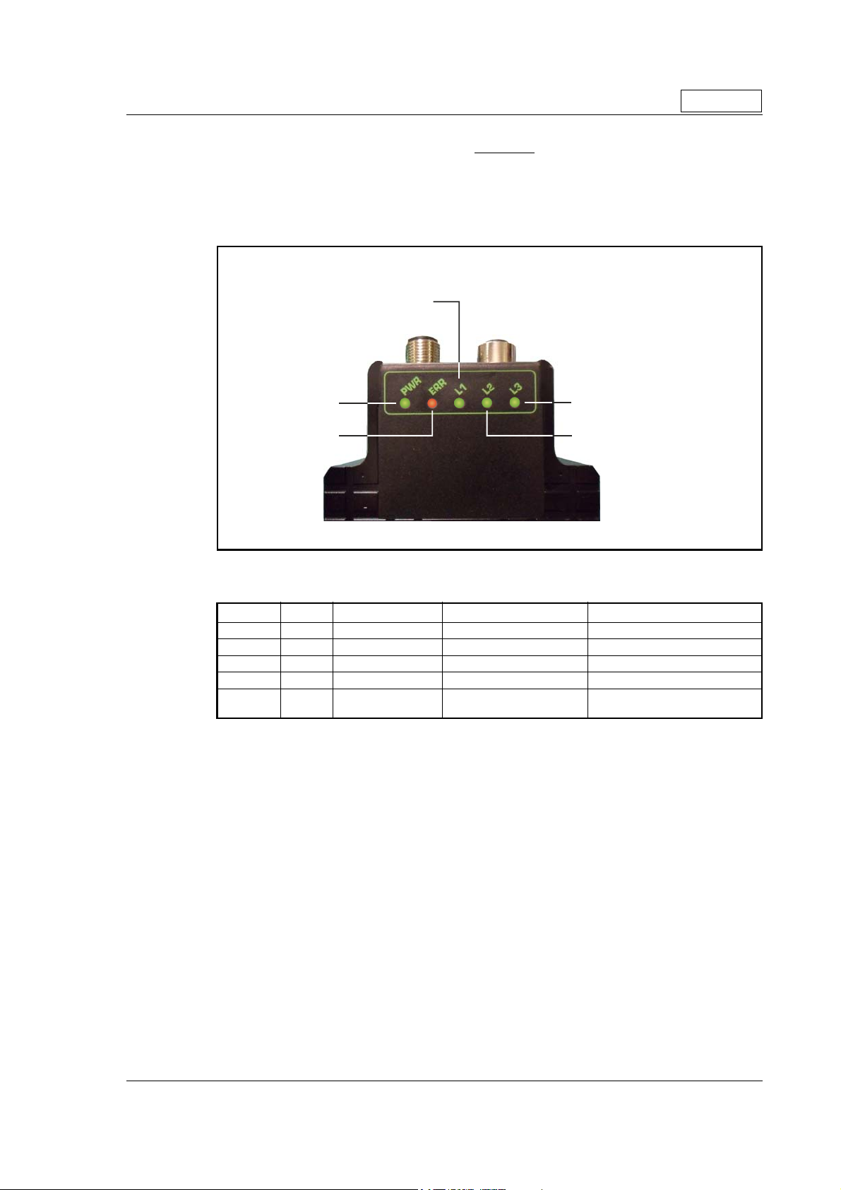
2.12 LED indicators at the MIS34x
Indi
Only MIS34x
2.12.1 LED’s - description for products without Ethernet or CANopen.
This description covers all MIS34x products with basic configuration without any Ethernet or CANopen such as MIS34xxxxQ5xxxx, MIS34xxxxQ9xxxx, MIS34xxxxFBxxxx, or
MIS34xxxxEWxxxx.
The LED's are used for indicating states and faults.
cator overview
Unused but user configurable
Power indicator
Error indicator
Motor in position
(can also be user configured)
Motor moving
(can also be user configured)
TT2344-01GB
LED indicator descriptions (default setup)
LED Text Colour Constant off Constant on Blinking
L1 Green Default Only when user configured Only when user configured
L2 Green Motor not moving Motor moving -
L3 Green Motor not in position Motor in position -
ERR Red No error - Error
PWR Green Power is not applied.
Power is applied to both
motor and module.
-
JVL Industri Elektronik A/S - User Manual - Integrated Stepper Motors MIS23x, 34x, 43x 51

2.13 LED indicators at the MIS34x
Indi
2.13.1 Indicator LED’s - description for products with CANopen.
This description covers all MIS34x products with build in Ethernet such as
MIS34xxxxP6xxxx.
The LED's are used for indicating states and faults.
cator overview
CANopen run LED
Only MIS34x
Power indicator
CANopen Error LED
Motor in position
(can also be user configured)
Motor moving
(can also be user configured)
TT2345-01GB
LED indicator descriptions (default setup)
LED Text Function Colour Constant off Constant on Blinking
CANopen
L1
run LED
L2 Motor moving Green Motor not moving Motor moving -
Motor in
L3
position
ERR
PWR Power Green Power is not applied.
CANopen
error LED
Green Please see the DS303-3 standard
Green Motor not in position Motor in position -
Red Please see the DS303-3 standard
Power is applied to both
motor and module.
-
52 JVL Industri Elektronik A/S - User Manual - Integrated Stepper Motors MIS23x, 34x, 43x

2.14 LED indicators at the MIS34x
)
)
2.14.1 Indicator LED’s - description for products with Ethernet.
This description covers all MIS34x products with build in Ethernet such as
MIS34xxxxExxxxx (except MIS34xxxxEWxxxx
The LED's are used for indicating states and faults. There is one power LED, two link/
activity LED's (one for each Ethernet connector), and 2 status LED's.
Indicator overview
General status indicator
Only MIS34x
Power indicator
Error indicator
Line activity indicator (CN3
Line activity indicator (CN2
TT2337-01GB
LED indicator descriptions
LED Text Colour Constant
off
L1 Green
L2 Green
L3 Green
ERR Red No error Error
PWR Green
NMT_CS_
NOT_
ACTIVE
No valid
Ethernet
connection.
No valid
Ethernet
connection.
Power is not
applied.
Notes:
Blinking: Flashing with equal on and off periods of 200ms (2.5Hz). Single flash: Repeating on for 200ms and
off for 1s. Double flash: Two flashes with a period of 200ms followed by 1s off period. Triple flash: Two flash
es with a period of 200ms followed by 1s off period.Flickering: Rapid flashing with a period of approximately
50ms (10 Hz).
Constant onBlinking Single
flash
NMT_CS_
OPERATIONAL
Ethernet
is
connected.
Ethernet
is
connected.
Power is applied to both
motor and
module.
NMT_CS
_STOPP
ED
- - - -
- - - -
NMT_CS
_PREOP
ERATION
AL1
Double
flash
NMT_CS
_PREOP
ERATION
AL2
Triple
flash
NMT_CS
_READY
_TO_OP
ERATE
Flickering
NMT_CS_B
ASIC_
ETHERNET
Activity on
line CN2
Activity on
line CN3
Booting
error
Power is
applied to
module but
no communi
cation with
motor.
-
-
JVL Industri Elektronik A/S - User Manual - Integrated Stepper Motors MIS23x, 34x, 43x 53

54 JVL Industri Elektronik A/S - User Manual - Integrated Stepper Motors MIS23x, 34x, 43x

3 Hardware Non-intelligent products
JVL Industri Elektronik A/S - User Manual - Integrated Stepper Motors MIS23x, 34x, 43x 55

Please contact your JVL distributor for further information.
56 JVL Industri Elektronik A/S - User Manual - Integrated Stepper Motors MIS23x, 34x, 43x

4 Using MacTalk
JVL Industri Elektronik A/S - User Manual - Integrated Stepper Motors MIS23x, 34x, 43x 57

4.1 Using the MacTalk software
S
S
p
etup save/open
The complete setup
can be either saved
or reloaded from a
file using these
buttons
Startup mode
The basic functionality
of the unit is
setup in this field.
Profile Data
All the main parameters for controling the motor behaviour
are setup in this field.
Driver Parameters
These fields are used
to define standby and
running current.
Gear Factor
The gear ratio can
be entered here
Motion Parameters
The distance the motor
has to run is entered here
ystem control
Use these buttons to save data
permanently, reset the motor etc.
Zero Search
All the parameters
regarding the position
zero search can
be s
ecified here.
4.1.1 MacTalk introduction
The MacTalk software is the main interface for setting up the MIS motor for a specific
application.
Error Handling
Use these fields to define error
limits for the position range etc.
Autocorrection
The parameters used
to get the correct position,
if it is a motor with encoder
Communication
The actual address of the
motor can be entered here
TT2145GB
Motor status
This field shows the
actual motor load,
position and speed etc.
Run status
Shows what the status of
the motor is. The Bus voltage
for the motor and the temperature of the driver is also shown
Inputs
The status of the digital inputs
are shown her and the analogue value
Outputs
The status of the outputs
are shown here and can
be activated by the cursor
Errors
If a fatal error occurs,
information will be
displayed here.
Warni ngs
Here different warnings are shown
Help Line
If parameters entered
Left area:
are outside their normal
values, errors are shown here.
Here it is possible to
Right area:
see if a motor is connected,
the type, version and serial no.
The program offers the following features:
- Selection of operating mode of the MIS motor.
- Changing main parameters such as speed, motor current, zero search type, etc.
- Monitoring in real time the actual motor parameters, such as supply voltage, input
status, etc.
- Changing protection limits such as position limits.
- Saving all current parameters to disc.
- Restoring all parameters from disc.
- Saving all parameters permanently in the motor.
- Updating the motor firmware or MacTalk software from the internet or a file.
The main window of the program changes according to the selected mode, thus only
showing the relevant parameters for operation in the selected mode.
The following pages describe the actual window for each mode and how the parameters
affect MIS motor operation.
58 JVL Industri Elektronik A/S - User Manual - Integrated Stepper Motors MIS23x, 34x, 43x

4.1 Using the MacTalk software
4.1.2 Toolbar description
The toolbar at the top of MacTalk contains the most commonly used features.
Open
Opens a setup file from disc and downloads the setup to the motor. If no motor is connected, the setup is shown in MacTalk and can be edited and saved to disc again.
Save
Saves the actual setup from the motor to a file. If no motor is connected, the actual offline settings (including module setups and program) are saved.
Save in flash
The complete actual setup in the basic motor will be saved permanently in the flash
memory. If the motor is powered down or reset, the saved setup will be used.
Reset position
Resets the position counter to 0. The content of the position counter can be monitored
in the right side of the main screen as “Actual position”.
Clear errors
Clears all the errors (if any). Please note that if an error is still present, the motor will
remain in the actual error state.
Reset motor
Reset the motor. Same as performing a power off / on operation.
Filter Setup
For specifying the filter setup of the analogue inputs.
STOP motor
Stops the motor immediately using a controlled deceleration ramp and puts the motor
into passive mode. If a program is present this is stopped as well.
This button shall be considered a functional stop button and is available using the
keyboard shortcut CTRL+F8.
Pressing the “Stop” button will immediately stop the motor by changing the currently
running mode to “passive” using a fast controlled deceleration curve.
Using a quickstep motor or a module that enables the user to execute RxP programs this
execution is also halted to prevent the motor from starting up if a startup-mode is setup
from a program.
Warning! Do not consider this button as an appropriate Emergency stop. Always fit an Emergency stop circuitry to your motor setup.
MacTalk Address
Only if more than one motor is connected to the same interface. The address specified
in this field will determine which motor is communicated with.
JVL Industri Elektronik A/S - User Manual - Integrated Stepper Motors MIS23x, 34x, 43x 59

4.1 Using the MacTalk software
4.1.3 Saving or opening a setup file to/from disc
The complete motor setup can be saved to disc or opened from disc
and transferred to the motor. The setup files can be saved anywhere
on the hard disc or a floppy disc. Saving and opening a file over a net
work is also possible.
The setup files use the extension MAC. By default, the setup files are
saved in the same directory in which MacTalk itself is also installed.
Other directories can be selected.
In case a motor is present and a disc file is opened the user is prompted for keeping the
connection or going offline and displaying the file-content.
The following message box appears.
-
TT1020GB
TT2264GB
Transfers Data to the motor
and displays the data in
MacTal k afterwards
Going off-line and displays
the data in MacTalk
If the user decides to go offline the following text box is presented.
Pressing “OK” disconnects the motor from the PC-application and all data can be edited
without any interruption in the motor.
60 JVL Industri Elektronik A/S - User Manual - Integrated Stepper Motors MIS23x, 34x, 43x

4.1 Using the MacTalk software
The following MacTalk view is presented.
As seen in the bottom info line, the motor is disconnected and the file data is currently
present in Mactalk. To re-establish communication with the motor, simply press the
”Go Online” -button and if any data has been changed a warning box appears enabling
the user to save current data before re-establishing communication with the motor as
this will overwrite existing data in MacTalk.
If data is changed in MacTalk the user is warned that current data in MacTalk may be
overwritten and needs to be saved. The following warning box is presented.
Yes
No
TT2328-01GB
Choosing “No” will immediately upload all motor data, pressing “yes” will save all data
in the open file.
JVL Industri Elektronik A/S - User Manual - Integrated Stepper Motors MIS23x, 34x, 43x 61

4.1 Using the MacTalk software
w
t
p
p
r
4.1.4 Main Screen
a) This field shows
the register values
in the controller
b) Here it is possible to
key in new values. After
pressing enter the value
ill be transferred to the
motor and thereafter be
read again from the controller
and be shown at point a.
Because of digitalizing of
he keyed in value, the
returned value in a) can be
different from the value in b).
c) By pressing the unit field it is possible to change between internal unit in the control
ler and the unit shown to the user.
E.g. If user unit for current is ARMS and the internal unit is 5.87mA (300ARMS correspond to 511 units.) Not all registers have different internal and user unit. Speed
for exam
le is alway specified in RPM.
TT2182GB
4.1.5 I/O Setup tab
Active level can be
chosen to high or
low on inputs
Dedicated Inputs
Selection for Inputs
HM, NKL and PL
An external encoder can
also be selected here and
defined as either quadrature
or pulse/direction type.
Selection if it shall
be Inputs or Outputs
Dedicated Outputs
Selection for outputs ”In position”,
”In Physical Position”, ”Error”
output. It can also be selected
if the pulses generated shall be
used internally, externally or both
and which output should be used
for pulse and direction signals
Input filters
Here the filter for the
digital inputs can be selected.
*) The analogue value of certain inputs can be read. Click at the input lamp and the analogue value will be shown. The upper value is the actual value and the lower value the
filtered value.
Selection if IO´s
shall use filters
Filter time constant can be adjusted here.
The same value is used for all inputs if filter
uts are enabled.
in
Selection of Inputs for
HM, NL and PL
Selection of output fo
In-Position and Errors
Status of the inputs *)
Status of the outputs
TT2183GB
62 JVL Industri Elektronik A/S - User Manual - Integrated Stepper Motors MIS23x, 34x, 43x

4.1 Using the MacTalk software
4.1.6 Register Screen
These registers can be used with FastMac commands. For example, the motor can run
to position P2 using velocity V2, acceleration/deceleration A2, running current T2, using
only a one byte command.
These values are not updated automatically. To update, place the cursor at the specific
register value to the left of the box for new values, and click. Otherwise they only update
at motor reset or power up.
JVL Industri Elektronik A/S - User Manual - Integrated Stepper Motors MIS23x, 34x, 43x 63

4.1 Using the MacTalk software
4.1.7 Advanced Screen
If it is desired to run the motor in the
opposite direction it can be done by
marking “Invert motor direction”
When this field is marked the motor
runs to the AP (Actual position) from
the encoder position when the motor
goes from passive to position mode
Remove the mark in this field and the
motor will start the program at start-up
Here it is possible to select different ways
of running a turntable and define
number of steps
It is possible to have a certain number
of motors doing the same by giving
them the same group id.
TT2 184GB
4.1.8 Test Screen
This screen is used for adjusting the Zero search sensor to the correct position when using the index pulse of an encoder. The index pulse should be in the green area. If not, the
sensor has to be adjusted.
64 JVL Industri Elektronik A/S - User Manual - Integrated Stepper Motors MIS23x, 34x, 43x

4.1 Using the MacTalk software
4.1.9 Scope Function
The Scope function is an excellent and necessary function for testing a new application
or finding errors in an existing system.
The Setup has to be selected to set up the Scope function correctly before use. Most registers in SMC75 can be selected for viewing, different trigger functions can be selected,
saving and loading scope pictures is possible, etc.
JVL Industri Elektronik A/S - User Manual - Integrated Stepper Motors MIS23x, 34x, 43x 65

4.2 How to update MacTalk
B
p
MacTalk can be updated directly from the internet at any time. It is recommended always
to use the latest version of MacTalk since it support the latest features and bugs may have
been found and corrected. Below is shown how to make an update of MacTalk.
Step 1
Choose the in the menu.
Step 2
MacTalk will now check if newer version exist
on the JVL server. If a newer version exist it
will automatically be downloaded and the release
notes can be seen in the window.
Update MacTalk Updates
Step 3
Press the button to download
the selected latest MacTalk.
The progress counter will now rise from 0
to 100%.
Step 4
When the download process is finished, the status
shows “ .
Press
of MacTalk.
Step 5
After MacTalk have restarted the version number
of the new MacTalk can be observed in the top
of the screen.
The com
Download & Install
Update ready”
“ in order to start the new version
OK”
lete update is finished !.
TT2342-01G
66 JVL Industri Elektronik A/S - User Manual - Integrated Stepper Motors MIS23x, 34x, 43x

4.3 How to update the motor firmware
S
p
The firmware in the motor can be updated directly from the internet at any time by using
MacTalk.
It is recommended always to use the latest version of the firmware available for the actual
MIS motor used since it will contain the latest features and bugs may have been found
and corrected. Below is shown how to make an update of the firmware. Notice that the
screen dumps below is based on the update of a MIS34x but could be any other size of
MIS motor.
tep 1
The firmware update will erase the existing user
setup of the motor. Use the Save button to save
the existing setup before updating the motor.
Then choose the in the
Updates
Step 2
The first list shown is only the newest firmwares
related to the actual motor connected.
It may also contains encoder and/or Ethernet
firmware if these features are present.
To see all files also older versions enable the
checkbox
Select the desired firmware, «SMCxxx firmware».
Press S to download the selected firmware.
The progress counter will now rise from 0
to 100%.
Step 3
When the download process is finished, the status
shows “ .
menu.
tart
Done”
Update Firmware
“Show all files”.
Step 4
The on-line information shown in the lower right
corner of the MacTalk main window will now
show the complete type of firmware and version.
The firmware update is now fully completed.
Please remember that the settings of the motor
is set back to default. But can be reinstalled by
opening the user setup file made initially in this
o
date sequence.
TT2343-01GB
Hint !: Some older products may not start after pushing the “start” button showed above.
If this is the case simply swich off power wait 5 seconds and reapply power. The update
should now start.
JVL Industri Elektronik A/S - User Manual - Integrated Stepper Motors MIS23x, 34x, 43x 67

4.4 How to update the encoder
S
p
B
Only MISxxx---H3--
firmware
If the motor has the H3 (absolute multiturn encoder feature) then the firmware can be
updated directly from the internet very easy at any time by using MacTalk.
It is recommended always to use the latest version of the firmware available for the actual
MIS motor used since it will contain the latest features and bugs may have been found
and corrected. Below is shown how to make an update of the encoder firmware.
tep 1
The encoder firmware update will erase the
existing user setup of the motor. Use the
button to save the existing setup before updating
the motor. Then choose the in
the menu.
Updates
Step 2
The first list shown is only the newest encoder
firmwares related to the actual motor connected.
It may also contains main and/or Ethernet
firmware if these features are present.
To see all files also older versions enable the
checkbox
firmware» S
firmware. The progress status counter will now
rise from 0 to 100%.
Step 3
When the download process is finished, the status
shows .“
If the download process for some reason did NOT
start/succed start from step 1 in this guide but
switch off power until the botton have«Start»
been activated and then switch on power.
. Press to download the selected
Done”
.“Show all files”
Select the desired firmware, «SMC... encoder
tart
Save
Update Firmware
Step 4
The on-line information shown in the lower right
corner of the MacTalk main window will now
show the complete type of main firmware
and optionally the ethernet firmware version
(if ethernet is present) including version.
The encoder firmware version is shown by
placing the mouse curser at top of the motor
for a short while.
The firmware update is now fully completed.
Please remember that the settings of the motor
is set back to default. But can be reinstalled by
opening the user setup file made initially in this
o
date sequence.
Hint !: Some older products may not start after pushing the “start” button showed above.
If this is the case simply swich off power wait 5 seconds and re-apply power. The update
should now start.
68 JVL Industri Elektronik A/S - User Manual - Integrated Stepper Motors MIS23x, 34x, 43x
TT2349-01G

5 Description of functions
JVL Industri Elektronik A/S - User Manual - Integrated Stepper Motors MIS23x, 34x, 43x 69

5.1 Adjusting the motor current
The current supplied to each of the step motor’s phases can be adjusted for standby and
running currents by changing the values of standby and running currents under “Driver
parameters” in the MacTalk program. The register is also accessible in general through
the serial interface.
The electronics automatically switches between the two currents by detecting the presence of step-pulses. If a rising edge is detected at the step-clock, the “Move current” is
selected. If no rising edge is detected during the period specified by “Standby time” at
the step-clock input, the current is automatically switched back to “Standby current”.
Values for the two currents are typically adjusted so that the Operating Current is significantly higher than the Standby Current, since the motor must be supplied with more
power to drive its load during acceleration and constant operation than when it is stationary.
Note that the maximum Standby Current normally will be set to 50% or lower of the
maximum current for the actual driver type. The only overriding consideration that must
be made in the adjustment of motor phase currents is that the thermal output of the motor must not exceed the maximum operating temperature of the step motor.
Cl k
Running
Standby
0
Standby time
TT2 2 0 8 G B
Current overview
MIS231 MIS232 MIS234 MIS340 MIS341 MIS342 Unit
Standby Current 0-3000 0-3000 0-3000 0-9000 0-9000 0-9000 mA RMS
Running Current 0-3000 0-3000 0-3000 0-9000 0-9000 0-9000 mA RMS
Holding Torque 0-1.2
[170] 0-1.9[269] 0-3.0[425] 0-3.0[425] 0-6.1[863] 0-9.0[1274] Nm [Oz-In]
If a MIS232 motor is used and the current is set to 3000 mA, the motor will be able to
deliver a torque of 1.6 Nm at low speed. If the current is set to 1000 mA, the motor will
be able to deliver 0.53Nm.
See Run_Current, page 124 for information about Running Current and Standby_Current,
page 125 for information about Standby Current.
70 JVL Industri Elektronik A/S - User Manual - Integrated Stepper Motors MIS23x, 34x, 43x

5.2 Auto Correction
5.2.1 Auto correction
Auto Correction is used in motors with a built-in encoder only. It is only used in position
mode to re-try a movement if the decoder position is too far from the target after the
pulse generator has stopped moving the motor – this will happen for instance if the
movement was physically blocked, the torque of the motor was insufficient, or a bad val
ue for start velocity or acceleration were used. It might also be used to handle occasional
mechanical oscillations.
The AutoCorrection system will first wait (unconditionally) for a certain time to allow the
initial movement to settle mechanically before testing for the target position. It will then
attempt a normal movement, using the same values for velocities and acceleration as the
movement that failed. It will continue until the encoder position is within the target win
dow, or the selected number of retries has expired.
Note that AutoCorrection will only start after the value of the P_SOLL register is
changed. In other words, changing P_SOLL (not just writing the same value again) will
reload the maximum number of retries and set the Auto Correction Active status bit.
The Auto Correction Active status bit will remain set until either the position is within
the target window or the max number of retries has been exhausted.
Also note that if the motor is used to control other motors by sending out the pulse and
direction signals on digital outputs, any extra movements caused by AutoCorrection will
send out additional steps to the other motors.
Only MISxxx---H2---
-
-
Registers affected:
• Register 33, IN_POSITION_WINDOW, specifies how many steps from the target
position the encoder must report before AutoCorrection is attempted.
• Register 34, IN_POSITION_COUNT, specifies the maximum number of retries. A
value of 0 (zero) effectively disables AutoCorrection.
• Register 110, SETTLING_TIME, specifies the number of milli-seconds to wait after a
movement before testing the encoder position against IN_POSITION_WINDOW.
In the present firmware versions, SETTLING_TIME will be used in AutoCorrection
mode only.
• Register 25, STATUSBITS, will still set bit 4 after the pulse generator has output all
the pulses to reach the target position (a theoretical In-Position). In AutoCorrection
mode, bit 2 will be set to reflect if the internal encoder position is within +/IN_POSITION_WINDOW steps from the target position P_SOLL (a physical In-Position). Also bit 1 will be set when AutoCorrection is active. Higher layer software
can
use this bit to detect when AutoCorrection has either completed or given up.
• Register 124, SetupBits, bit 1 can be set to have the firmware maintain the InPhysical Position bit 1 in register 25 all the time, also during a movement. If this bit is not
set, the InPhysicalPosition bit will only be maintained after the motor has stopped
moving.
Continued next page
JVL Industri Elektronik A/S - User Manual - Integrated Stepper Motors MIS23x, 34x, 43x 71

5.2 Auto Correction
• Register 137, INPOS_Mask, is used to select the outputs to reflect the status of the
two bits InPosition (bit 4 in the STATUSBITS register) and InPhysical Position (bit 2
in the STATUSBITS register). The 8 lowest bits will select the mask for InPosition and
the 8 highest bits will select the mask for InPhysicalPosition. Any combination of bits
can be set to have zero, one or more outputs reflect each of the two InPosition bits.
The MacTalk program only supports setting a single output for each bit, however,
since this is the normal case.
Only MISxxx---H2---
72 JVL Industri Elektronik A/S - User Manual - Integrated Stepper Motors MIS23x, 34x, 43x

5.3 Absolute position back-up
The absolute position backup system is activated when a voltage goes under a preset value. Then all absolute multi turn information is saved to flash at once.
All data are then recalled from flash memory at startup and the motor has the absolute
position information saved at power down.
The input on which the voltage drop is monitored, is selected between all standard I/O’s,
the P+ (12-48V power supply MIS23x or 12-80V MIS34x) and a special input (see the
“registers involved –section” later in this chapter).
When the operation is triggered, the motor will not be able to work at all until the power
has been cycled off and on again.
It is required that the supply control voltage drops relatively slowly to allow time to save
the values to flash memory. This can be secured by adding, if necessary, a large capacitor
on the CV supply voltage and powering on/off the external power supply on the AC side.
Beside the position information also error tracking information is saved. This is very helpful for later troubleshooting.
5.3.1 Registers involved
Register 142, Analogue Input Selection, selects which analogue input to use for measuring the power supply. It can be:
1 to 8 for analogue inputs IO1 to IO8, using the unfiltered values for fast response.
81 to 88 for analogue inputs IO1 to IO8, using the filtered values for noise immunity.
12 for the 12-48V (12-80V MIS34x) power supply P+ and finally 13 for a special input
developed for this feature alone (from HW rev. 1.7 and up).
Any other value will disable the flash backup system.
Only MISxxx---H2---
When running the motor from 30 Volts or less, it can be convenient to connect the bus
voltage with the control voltage (CV) supply, and use the value 12 in register 142 to mon
itor the control voltage.
When running the motor from 48 Volts, this is not allowed and can damage the controller
board if voltage exceeds 30V.
Register 141, Save Threshold Voltage, selects the voltage threshold, that will trigger the
flash backup save operation (and stop all other motor operation).
When register 142 has the value 12, the scaling/unit of register 141 is the same as register
97, Bus Voltage (1023 = 111.4V).
The register 142 has the values of 1-8 or 81-88, the scaling/unit of register 141 is the
same as registers 81-96 (1023 = 5.0V)
Register 139, Acceptance Voltage, selects the voltage threshold that defines when the
power supply is ready to use for erasing flash memory after power up. The scaling/unit
is the same as register 141.
Register 140, Acceptance Count, selects the number of times the Acceptance Voltage
must be measured after power up before the flash erase operation is started.
When using values 1-8 or 12 for register 142, the count is in units of ~245 microseconds.
When using values 81-88, the count is in units of 10 milliseconds.
Register 124, SetupBits, selects to use Flash-based Absolute Multi turn Encoder functionality when bit 11 is set.
-
JVL Industri Elektronik A/S - User Manual - Integrated Stepper Motors MIS23x, 34x, 43x 73

5.3 Absolute position back-up
5.3.2 Reading the Flash Backup data
The Error tracking and diagnostics counters can be copied to the general purpose register P1-8 and V1-8 by writing to the Command register 24. This can also be done by writing the value into MacTalk Command field on the Advanced tab and pressing Enter.
Saved positions, Run Seconds and counters
A command value of 260 will result in:
P1= Last saved values of the Actual Position, P_IST
P2 = Total number of times motor has been powered down
P3 = Total number of seconds the PCB has been running (with a valid CV supply voltage)
P4 = Total number of times a PLC program has been uploaded.
P5 = Total number of times the motor parameters have been saved to flash (button in
MacTalk).
P6 = Last saved external encoder value
P7 = Last saved SSI encoder value
V3 = Last saved Encoder position (internal magnetic encoder)
A command of 265 will result in:
P1 = Last timestamp (in Run Seconds) the Follow Error was set.
P2 = Last timestamp (in Run Seconds) the Output Driver Error was set.
P3 = Last timestamp (in Run Seconds) the Position Limits Exceeded Error was set.
P4 = Last timestamp (in Run Seconds) the Low Bus Voltage Error was set.
P5 = Last timestamp (in Run Seconds) the Over Voltage Error was set.
P6 = Last timestamp (in Run Seconds) the Temperature Too High Error was set.
P7 = Last timestamp (in Run Seconds) the Internal Error (memory test error) was set.
Only MISxxx---H2---
V1 = Number of times the Follow Error was set since the last Error Reset command.
V2 = Number of times the Output Driver Error was set since the last Error Reset com-
mand.
V3 = Number of times the Position Limits Exceeded Error was set since the last Error
Reset command.
V4 = Number of times the Low Bus Voltage Error was set since the last Error Log Reset
command.
V5 = Number of times the Over Voltage Error was set since the last Error Log Reset
command.
V6 = Number of times the Temperature Error was set since the last Error Log Reset
command.
V7 = Number of times the Internal Error was set since the last Error Log Reset com-
mand.
The command 266 will set all error timestamps and all error counters to zero.
All commands are entered in register 24 or in the Command field in Mactalk
74 JVL Industri Elektronik A/S - User Manual - Integrated Stepper Motors MIS23x, 34x, 43x

5.3 Absolute position back-up
Additional information saved when position backup is activated.
Error tracking where the number of times each type of error has occurred since the last
reset error operation is remembered together with a timestamp for the last time the er
ror occurred. The timestamp is in Run seconds.
Monitoring of total run time in seconds, called Run Seconds
Counting of the number of times:
- A new PLC program has been saved.
- The motor parameters have been saved.
5.3.3 The Flash backup feature support in MacTalk
All setup-values are accessible from MacTalk.
Acceptance count Register 140
Acceptance voltage Register 139
Save threshold voltage reg. 141
Input selection Register 142
Only MISxxx---H2---
-
SetupRegister Register 124
TT2265GB
The QuickStep series offers many ways of position control using encoders. From firmware V.2.6 SSI standard encoder is supported, and linear absolute positioning is possible
using a SSI-encoder.
JVL Industri Elektronik A/S - User Manual - Integrated Stepper Motors MIS23x, 34x, 43x 75

5.4 SSI encoder/sensor interface
5.4.1 General information on how to connect the SSI device.
The SSI interface is based on 2 differential lines.Both lines are available in the M12 connectors and are named A1+, A1- and B1+,B1- (4 wires) In order to see the exact physical location of the signals please consult the pages:
- Connector overview for the MIS23x, page 33 and
- Connector overview for the MIS34x, page 35
The function of the signals is as follows:
- Line A1+ and A1- transmit a clock signal to the SSI device.
- Line B1+ and B1- receives the data stream from the SSI device.
5.4.2 Setup and operation of the SSI function when using MacTalk.
When using the MacTalk Windows program supplied by JVL the following descriptions
must be used.
There are a few differences between the different members of the MIS family.
MIS23x / SMC75:
No special setup is required. A read command will simply take care of reading data from
the SSI device if its connected as described above.
MIS34x / MIS43x / SMC85:
These products offer a very flexible interface for connecting many different devices.
In order to setup these members for SSI support 2 codes need to be executed in a RxP
program. These 2 commands setup the RS485 interface covering the 4 lines to the SSI
device for transmitting a clock and receiving data from to/from the SSI device.
TT2479-01GB
76 JVL Industri Elektronik A/S - User Manual - Integrated Stepper Motors MIS23x, 34x, 43x

5.4 SSI encoder/sensor interface
5.4.3 MacTalk SSI Setup - only MIS23x and SMC75.
From MacTalk all configurations and settings are accessible.
Choosing the “Advanced” -Tab gives access to the “SSI encoder value” and the “SSI encoder setup”.
The SSI encoder value is sampled by typing in the 321 into the command field.
This can also be done from an RxP program or the serial interface from a master controller connected to the RS485 interface.
Field: “Number of Data bits”
Selects the number of data bits in each SSI transfer. The valid range is 0 to 31, corresponding to 1 to 32 data bits. Set this value according to the actual SSI device connected.
Please consult the data sheet for the actual SSI device concerning which value to be used.
Field: “Clock frequency”
Selects the maximum clock speed in units of 10 kHz. The valid range is 0 to 59, corresponding to 10 kHz to 600 kHz.
Set this value according to the actual SSI device connected.
Please consult the data sheet for the actual SSI device concerning which value to be used.
Field: “Prepare time” (Clk to Data)
Selects the prepare time in micro seconds at the start of an SSI transfer, corresponding
to time t1 - please see
The valid range is 0 to 255 corresponding to 1 to 256 micro seconds.
Field: “Disable intr. when reading SSI”
Because of the special timing requirements of the SSI standard it is sometimes required
to disable all interrupts in the quickstep-processor.
This must be done in order to prevent false encoder data when reading because of other
processes in the processor absorbing time during the SSI read cycle.
To disable all interrupts in the processor while reading the encoder value, simply check
this box.
The SSI encoder reading is supported in QuickStep firmware from V2.7.
The SSI interface principle of operation., page 82.
JVL Industri Elektronik A/S - User Manual - Integrated Stepper Motors MIS23x, 34x, 43x 77

5.4 SSI encoder/sensor interface
MacTalk
MIS34x / MIS43x / SMC85 :
The interface for these devices is different, primarily because of the data validation function.
:
«Advanced tab»
Field: “Number of Data bits”
Selects the number of data bits in each SSI transfer. The valid range is 1 to 31.
Set this value according to the actual SSI device connected. Please consult the data sheet
for the actual SSI device concerning which value to be used.
Field: “Clock frequency”
Selects the maximum clock speed in units of 10 kHz. The valid range is 1 to 255, corresponding to 10 kHz to 2.55 MHz.
Set this value according to the actual SSI device connected. Please consult the data sheet
for the actual SSI device concerning which value to be used.
Field: “Prepare time” (Clk to Data)
A typical SSI device needs a so called prepare time to sample the position data before
transfer. This field is dedicated to type in the prepare time in micro seconds at the start
of an SSI transfer. The valid range is 1 to 255, corresponding to 1 to 255 micro seconds.
Set this value according to the actual SSI device connected. Please consult the data sheet
for the actual SSI device concerning which value to be used.
Field “Max. sample deviation”
Selects the maximum allowed deviation between two samples. The valid range is 1 to
8191. This function is ment to be an extra safety to avoid invalid reading of position data
caused by noise influencing the signal. Please bear in mind that if the external SSI device
is tracking the position of something that moves the value and thereby the deviation from
one sample to the next can be significant.
78 JVL Industri Elektronik A/S - User Manual - Integrated Stepper Motors MIS23x, 34x, 43x

5.4 SSI encoder/sensor interface
Field: “Number of Samples”
Selects the number of samples in each SSI measurement. If all samples stay below the
“Max. sample deviation” value (described earlier in this text), no retry is required. If one
pair of samples fails the whole measurement fails and a retry is attempted if allowed ac
cording to the “Read Retries” parameter.
Field: “Read Retries”
Selects the number of retries before time out and reporting an error.
The MIS34x / MIS43x and SMC85 has a build in data validation function which automatically compares the current sample with the previous and makes sure that the deviation
is within the “Max. sample deviation” limit. “Number of samples” determines how many
samples one measurement contains. If the measurement fails, a retry is attempted if
number of retries has not exceeded the “Read Retries” value.
|Sample(x) – Sample(x+1)| < (Max_sample_deviation) = OK
|Sample(x) – Sample(x+1)| > (Max_sample_deviation) = ERROR
If the number of retries has exceeded the “Read Retries” value and the measurement still
reports an error, the reading will be discarded and “SSI Encoder value” still shows the
last correct measurement.
An error bit will be set in the ERR_BITS register (34) on position 11.
-
MacTalk will report this error :
TT2481-01GB
Additional hardware settings:
Some LIKA SSI encoders offer 2 additional hardware settings, for instance “Zero Setting”
and “Invert Counting Direction”. These settings can be controlled by having user I/O 5
and 6 set as output. Consult the datasheet for the specific encoder to read more about
the behaviour of these settings and to make sure they are available.
JVL Industri Elektronik A/S - User Manual - Integrated Stepper Motors MIS23x, 34x, 43x 79

5.4 SSI encoder/sensor interface
5.4.4 Setup and operation of the SSI function when NOT using MacTalk.
(below descr. covers all MIS and SMC products)
Following lines describe how to access relevant registers when having a SSI device connected.
When reading the data from the SSI device the data will be places as a signed 32 bit integer in register 47 shortly after the read command have been executed.
The time before data is present can be calculated after following formular:
Total time from the read command 321 is executed until valid data is present is equal:
Time = Prepare time (timer) + (1/ Clock frequency * (Number of Data bits+1))
Exampel:
Encoder used have following setup:
Prepare time = 100uS (0.0001 sec.)
Clock frequency = 10kHz (10000Hz)
Number of data bits = 25
0.0001+ (1/10000 * (25 + 1) = 0.0027 sec. = 2.7ms
Note: (only for MIS34x/MIS43x and SMC85)
If noise have affected the signal the time before valid data is presented will be longer.
Depending on the specific setting for the data validation function.
The position data from the encoder is presented in register 47 as shown below.
Register 47 - «EXTENCODER» (External encoder data) - Signed 32 bit integer.
31 30 29 28 27 26 25 24 23 22
2120191817161514131211109876543210
Position data available as a signed 32 Bit integer
TT2482-01GB
A few differences exist between the product families concerning following registers.
MIS23x / SMC75:
Register description.
Register 107 - «SSI_SETUP1» - Unsigned 16 bit integer.
1515141413131212111110109988776655443322110
Disable
interrupts
Register 111 - «SSI_SETUP2» - Unsigned 16 bit integer.
«Clock frequency»
(x 10kHz)
Reserved
«Number of
databits»
0
TT2484-01GB
«Wait time»
(1µS * n)
«Prepare time»
(1µS * n)
80 JVL Industri Elektronik A/S - User Manual - Integrated Stepper Motors MIS23x, 34x, 43x

5.4 SSI encoder/sensor interface
)
MIS34x / MIS43x / SMC85 :
These products offer a more advanced SSI implementation with a data validation function. This requires more parameters to be set up before an SSI transfer.
Register 107 - «SSI_SETUP1» - Unsigned 32 bit integer.
31313030292928282727262625252424232322
2121202019191818171716161515141413131212111110109988776655443322110
«Read
retries»
(2^n)
«Max. sample deviation»
(1-8191)
«Clock frequency»
(x 10kHz)
Register 111 - «SSI_SETUP2» - Unsigned 32 bit integer.
22
Not used / reserved
«Number
of
samples»
«Prepare time»
«Gray to
Bin converter»
Activator
(Set to 1" for Gray to bin
"
Set to for no conversion
"0"
(1µS * n)
«Number of
databits»
TT2483-01GB
0
JVL Industri Elektronik A/S - User Manual - Integrated Stepper Motors MIS23x, 34x, 43x 81

5.4 SSI encoder/sensor interface
5.4.5 The SSI interface principle of operation.
When the differential lines are used for SSI, the A1+/- lines work as a clock signal to the
encoder, while the B1+/- signals work as a data signal from the encoder to the controller
(MISxxx/SMCxx).
The figure above shows the SSI protocol principle.
The clock line is normally high. When a reading is requested, the clock goes low for t1
micro seconds (see illu. above) to allow the encoder to sample and prepare a value.
On the first rising edge of the clock (1), no sampling is done but on the second rising edge
of the clock (2) the first data bit is read from the data line.
Shortly after reading the bit value, the MISxxx/SMCxx will set the clock high and execute
another cycle, where the data bit is sampled just before each rising clock.
After the last data bit has been sampled, the clock stays high.
82 JVL Industri Elektronik A/S - User Manual - Integrated Stepper Motors MIS23x, 34x, 43x

5.5 Absolute Multi-turn Encoder
5.5.1 Introduction
MIS34x motors equipped with the optional absolute multi-turn encoder (H3xx option)
offer the possibility to keep track of the position regardless if power is connected or not.
When this option is present a mechanical zero search is only necessary one time after
installation and the system will keep track of the actual motor position at any time after
wards.
The encoder is based on a magnetic principle which do not offer the same resolution and
precision as the more expensive optical based solutions. It do however offer the advan
tage to keep track of the position without power applied. The magnet principle is also
much more tolerant to mechanical stress such as shock and extreme temperatures.
The absolute multi-turn option offers the following main features.
Encoder:
Resolution 409.600 counts per revolution displayed (internal 1024 cpr)
Accuracy +/- 0,1% of full scale
Repeatability +/- 0,1% of full scale
Position range -5245 to +5245 motor revolutions (+/- 2^31 motor counts)
Motor:
Resolution 409.600 counts per revolution (standard)
Only MISxxx---H3--
-
-
As seen above the motor resolution is much higher than the encoder resolution. The encoder option is however mostly used for stall detection at the motor (motor loose its position) and for this situation the encoder will be adequate since the motor can only stall
in multiples of a 1/50 shaft revolution corresponding to 7.2 mechanical degrees.
JVL Industri Elektronik A/S - User Manual - Integrated Stepper Motors MIS23x, 34x, 43x 83

5.5 Absolute Multi-turn Encoder
p
5.5.2 How to Preset the encoder position.
After installing the motor it is normally desired to make an alignment of the encoder position which represent the "Actual position" compared to the actual physical position of
the motor and its load.
This operation is recommended to do in the following manner.
1. Set the motor in a known position
2. Insert the corresponding position value as shown below.
3. Press the “Set position” button to preset the new position value.
4. The encoder position and all other relevant position registers are now preset with
the new value. No further action is needed. The motor will remember this change
also during power off.
Select the «Absolute positioning» tab
Only MISxxx---H3--
First the new value that the encoder
must be preset to must be typed here
Secondly press «Set position» in order to
TT2339-01GB
84 JVL Industri Elektronik A/S - User Manual - Integrated Stepper Motors MIS23x, 34x, 43x
reset the encoder counter with the new value.

5.5 Absolute Multi-turn Encoder
p
.
5.5.3 Position "Auto-correction"
This feature is only active when the motor is in position mode.
The auto-correction feature is only used when the motor has stalled and not reached its
final target position within the given position window.
Each time the motor has done a movement the "Actual position" counter and the "Encoder position" counter is compared.
If the difference without sign is within the value specified in the "In position window" as
shown below no further action is taken.
If the difference is larger than the value in the "In position window" the motor will try to
correct the position by doing a new motor movement. The "Max number of retries" is
the number of times the motor will try to correct the position, and the "Settling time be
tween retries" is the time the motor will wait between each retry.
Only MISxxx---H3--
-
When selected the in position flag will
realtime indicate if the motor is within the
osition window compared to a perfect move.
An autocorrection after end movement is
performed if the difference between the
actual position and the encoder position
is more than the value specified in this field
The max number of autocorrection retries
per movement is specified here.
The settling (delay) time between the retries
when doing autocorrection.
TT2338-01GB
JVL Industri Elektronik A/S - User Manual - Integrated Stepper Motors MIS23x, 34x, 43x 85

5.5 Absolute Multi-turn Encoder
5.5.4 Operation of the encoder when NOT using MacTalk.
The following description is useful for reading the encoder or presetting a new encoder
value if MacTalk is not used for the communication.
This could for example be when using one of the Ethernet options.
Reading the encoder position.
The encoder position is read from the register 46 (AbsEncPos). The value is scaled to
match the motor resolution which means 409600 counts per motor revolution.
Presetting a new encoder position.
Write the new encoder value to register 144 (P_NEW) and afterward write 316 into the
register 24 (Command reg). Notice that this value must match the motor resolution
which means 409600 counts per motor revolution.
Optionally the desired position value (P_SOLL and P_IST) can be set to the same position
by writing the value 119 to the register 24 (Command reg).
Only MISxxx---H3--
86 JVL Industri Elektronik A/S - User Manual - Integrated Stepper Motors MIS23x, 34x, 43x

5.5 Absolute Multi-turn Encoder
t
t
5.5.5 Position retention time
A special high temperature "Poly-carbon mono fluoride" lithium cell is used as backup for
the absolute multi-turn encoder. Compared to standard cells this one has extremely
good performance at high temperatures up to 125 degrees Celsius.
Normal lithium cells self-discharge very rapidly just being exposed to a temperature of
60 degree celsius.
The retention time of the position when the motor is not supplied is better than 10
years. This depends of how long time the motor is in use and the temperature.
The self-discharge at 85 degrees celsius (185 degrees Fahrenheit) is 6% per year, and
2% per year at 40 degrees celsius (104 degrees Fahrenheit).
Concerning the retention time, there is no big difference if the motor is in use at a high
temperature or it is powered down (low temperature).
The absolute multi-turn encoder's current consumption from the battery when the motor is not externally powered, is max. 1.5µA.
The curves below shows what is considered as a worst case scenario for the retention
time. The curves are based on 40 and 85 degree celsius (108/185F) without any exter
nal power applied to the motor meaning that the internal battery have to supply current to the encoder circuitry all the time. The current consumption of the encoder
circuitry is however not dominant compared to the internal leakage current in the bat
tery.
Only MISxxx---H3--
-
-
Hints to optimise the battery lifetime:
1. Avoid to place the motor in an environment with high temperatures.
2. Set the running and especially the standby motor current as low as possible in order
not to heat up the motor unnecessarily.
3. Keep the external power applied as much as possible.
Battery life time as function of temperature
Batt. level (%)
120
100
80
Battery level when temp. = 40deg.(108F)
60
Battery level when temp. = 85deg.(185F)
40
20
Bat
Bat
0
0 1 2 3 4 5 6 7 8 9 1011121314151617181920
Years
JVL Industri Elektronik A/S - User Manual - Integrated Stepper Motors MIS23x, 34x, 43x 87

5.5 Absolute Multi-turn Encoder
5.5.6 Firmware Upgrade (version 2.20 and earlier)
In MacTalk, select "Updates", "Update Firmware" to open the Firmware Upgrade window.
When selected the in position flag will
realtime indicate if the motor is within the
position window compared to a perfect move.
Only MISxxx---H3--
TT2340-01GB
Important !: If the motor contains main firmware (SMC85 firmware) older than ver-
sion 2.00 it is necessary to update the encoder firmware before updating
the main firmware (SMC85 firmware). See chapter
How to update the
motor firmware, page 67.
Updating the encoder firmware:
1. Select the latest version of "SMC85/MIS34x encoder firmware".
2. Press "Start" to begin loading the new firmware.
3. When done, press "Exit" and wait for the motor to restart.
After motor restart
4. Since the encoder position is not valid after a firmware update please follow the
chapter -
How to Preset the encoder position., page 84.
5. Finally press the "Clear Error” button in the main toolbar in order to clear any errors
caused by the update.
88 JVL Industri Elektronik A/S - User Manual - Integrated Stepper Motors MIS23x, 34x, 43x

5.6 Position Limits
5.6.1 Position limitation features.
The MIS motor family offers 2 different methods of limiting the movement of the motor.
In some applications it may be fatal or critical if the position of the motor passes a certain
mechanical position range.
The 2 methods are as follows:
• End of Travel Limit Inputs.
Limit switch inputs for detecting the physical position of the mechanics.
• Software Position Limits.
Limits in software to prevent the motor to move outside a certain position range.
The next pages describe the function and how to use these 2 methods.
5.6.2 End-of Travel Limit Inputs
Any of the 8 general inputs (IO1 to IO8) can be used as limit inputs. The input can be set
from MacTalk or via register
Positive limit (PL)
Activation of the Positive limit (PL) Input will halt motor operation if the motor is moving
in a positive direction. The motor can however operate in a negative direction even if the
PL Input is activated.
NL_Mask, page 141 or PL_Mask, page 142.
Negative limit (NL)
Activation of the Negative limit (NL) Input will halt motor operation if the motor is mov-
ing in a negative direction. The motor can however operate in a positive direction even
if the NL Input is activated.
Below is shown how to select the desired input(s) to be used for the limit switch(es).
Notice that the inputs default are set to disabled. Its also possible to select only one input
for one of the directions and keeping the opposite input disabled.
Please use the general chapter I/O Setup tab, page 62 for setting up the active level, optional input filter etc.
How to select the input(s) for the End of Travel Limit
TT2471-01GB
Select the negative and/or positive limit input(s) in these fields.
JVL Industri Elektronik A/S - User Manual - Integrated Stepper Motors MIS23x, 34x, 43x 89

5.6 Position Limits
V
Relati
The following illustration shows the timing and motor behaviour when the limit switch
inputs are activated.
on between limit switch inputs and the motor behaviour
elocity
(unsigned)
2
1
Negative Limit switch activated
here when motor moves in
negative direction
1
When the motor has passed the point where the limit switch is activated the motor is stopped.
The stop may cause an error which is determined by the setting
(placed at the main tab in MacTalk),
the motor is possible again.
When not disabled :
When disabled:
2
When the motor is commanded to move in the opposite direction (away from the limit switch)
the normal acceleration setup is used.
Please notice that if the activated limit switch has caused an error then remember to clear the
error register before the motor can be set back in normal operation.
TT2472-01GB
(default)
= Motor stop after limit switch activation
= Moving away from the limit switch
Positive Limit switch activated
here when motor moves in
positive direction
which may require an extra procedure before motion of
The motor will stop with an infinitive high deceleration.
The motor will go to passive mode and stay in passive mode.
The error need to be cleared and a mode have to be re-entered
in order to move the motor in the opposite direction away from
the limit point.
The motor will stop. No error is reported and the motor can
immidately be moved in the opposite direction without further
action.
2
1
Disable Error on travel limit
Position
-
+
90 JVL Industri Elektronik A/S - User Manual - Integrated Stepper Motors MIS23x, 34x, 43x

5.6 Position Limits
5.6.3 Software Position Limits.
These limits are software limits and are can optionally be used to prevent the motor to
move outside a certain position range in cases where for example faulty position com
mands are send to the motor or similar cases.
How to setup the Position limits
TT2473-01GB
-
Select the negative and/or positive limit(s) in these fields.
CAUTION
move if the position limits are changed after a situation where
they have been passed and have forced the motor to stop.
!
The limits has the same function as the physical End of travel inputs but is a pure software
limitation. Default for both parameters is 0 meaning that the feature is disabled.
Notice that if one of the parameters are different from 0, both values are activated.
Positive Position Limit (PLS)
When the motor is moving in a positive direction in position mode or gear mode, the motor will stop at Position Limit Max. In velocity mode the speed will internally be set to 0
when passing Position Limit Max, causing the motor to decelerate and stop.
Negative Position Limit (NLS)
When the motor is moving in a negative direction in position mode or gear mode, the
motor will stop at Position Limit Min. In velocity mode the speed will internally be set to
0 when passing Position Limit Min, causing the motor to decelerate and stop.
Its recommended to set the motor in passive mode before
changing the limits in order to avoid personal injuries.
-
Please notice that the motor may start to
JVL Industri Elektronik A/S - User Manual - Integrated Stepper Motors MIS23x, 34x, 43x 91

5.6 Position Limits
d
V
The illustration below shows how the software limits take effect at the motor movement.
Relation between software limits and the motor behaviour
elocity
(unsigned)
2
2
1
Function when motor is in or
The motor will decelerate according to the general acceleration/deceleration setting and stop at
the limit point.
Moving backwards from the stop point is done similarily.
The stop may cause an error which is determined by the setting
(Placed at the main tab in MacTalk), which may require an extra procedure before motion of
the motor is possible again.
When not disabled :
When disabled:
2
Function when the motor is in .
The motor will move until it reaches the limit point whereafter it will decelerate with the
Emergency deceleration and stop behind the limit point.
Moving backwards from the stop point is done similarily.
The stop may cause an error which is determined by the setting
(Placed at the main tab in MacTalk), which may require an extra procedure before motion of
the motor is possible again.
1
Position Limit minimum
Position mode Gear mode .
(default)
= Velocity Mode
= Position and Gear mode
Position Limit Maxium
The motor will stop and an error is reported. The motor will go
to passive mode and stay in passive mode.
The error need to be cleared and a mode have to be re-entere
in order to move the motor in the opposite direction away from
the limit point.
The motor will stop. No error is reported and the motor can
immidately be moved in the opposite direction without further
action.
Velocity mode
2
1
Disable Error on travel limit
Disable Error on travel limit
2
Position
-
+
When not disabled :
When disabled:
TT2475-01GB
For further information about the internal registers that are behind the fields in MacTalk
(default)
The motor will stop and an error is reported. The motor will go
to passive mode and stay in passive mode.
The error need to be cleared and a mode have to be re-entered
in order to move the motor in the opposite direction away from
the limit point.
The motor will stop. No error is reported and the motor can
immidately be moved in the opposite direction without further
action.
see also
MIS23x: Min_P_IST, page 128 and Max_P_IST, page 129.
MIS34x/43x: Min_P_IST, page 163 and Max_P_IST, page 164.
92 JVL Industri Elektronik A/S - User Manual - Integrated Stepper Motors MIS23x, 34x, 43x

5.6 Position Limits
5.6.4 Limit Error handling
A bit will be set in the Controller’s warning register if either the NL, PL, NLS or PLS has
been activated or are active. See
(MIS34x and MIS43x).
Bits 0 and 2 are common for PL and PLS. Bits 1 and 3 are common for NL and NLS.
The motor will stop and activate an error, when reaching a limit. When a limit error is
active the motor is forced into passive mode, and further movements are impossible. To
reset the error press the ”Clear Errors” button in MacTalk. Clearing errors automatically
also clears warnings too.
5.6.5 Limit handling optional only for MIS34x/43x
The MIS34x and MIS43x motors can be configured to stop and stay in the current mode
when reaching a limit. This can be done by setting the DisableErrorOnTravelLimit-bit in the
SETUP_BITS register. See
When the NoErrorOnPositionLimit-bit is set the motor decelerates with the ”Error deceleration” on travel limits in all modes and on position limits in velocity mode. The normal acceleration is used on position limits in position and gear mode.
Warn_Bits, page 130 (MIS23x) and Warn_Bits, page 165
Setup_Bits, page 174.
JVL Industri Elektronik A/S - User Manual - Integrated Stepper Motors MIS23x, 34x, 43x 93

5.7 Mechanical Zero search
5.7.1 Zero search Input
Any of the 8 inputs can be used as Home input for the zero search function. A zerosearch occurs when the Controller receives the seek zero search command by changing
Mode_Reg (
The Home Input can be set from MacTalk or via register Home_Mask (Section 8.2.68,
page 142)
It is possible to see when a zero-search is finished by reading a bit in Status bits (Sec-
tion 8.2.21, page 128
Section 8.2.3, page 122)
94 JVL Industri Elektronik A/S - User Manual - Integrated Stepper Motors MIS23x, 34x, 43x

6Modes
The QuickStep motor offers the following modes of operation:
Passive: The motor will be in a completely passive state but
communication is active and internal registers can be set up.
Velocity: The motor velocity can be controlled using MacTalk software
or by setting register 5 (V_SOLL) using serial or program commands.
Position: The motor position can be controlled using MacTalk software
or by setting register 3 (P_SOLL) using serial or program commands.
Gear: The motor position and velocity can be controlled by pulse and direction
or encoder signals at IN1 and IN2.
The gear ratio can be set to a large ratio using register 14 (GEAR1) and
register 15 (GEAR2).
Zero search type 1 and type2:
Searches for sensor to define a zero position (Reference point).
JVL Industri Elektronik A/S - User Manual - Integrated Stepper Motors MIS23x, 34x, 43x 95

6.1 Passive Mode
6.1.1 Passive Mode
After power up, the controller will start up in passive mode. This means that it is possible
to communicate and read/write to/from registers, but no current is supplied to the mo
tor. It should thus be possible to turn the motor shaft as no voltage is connected to the
motor. If there is encoder feed-back, the encoder counter will always register the cor
rect position.
-
-
96 JVL Industri Elektronik A/S - User Manual - Integrated Stepper Motors MIS23x, 34x, 43x

6.2 Velocity Mode
6.2.1 Velocity Mode
In this mode, the QuickStep motor controls the motor velocity via the Max Velocity setting. This mode is typically used for simple tasks or for applications in which an overall
unit, such as a PC-board or PLC, controls velocity and positioning.
JVL Industri Elektronik A/S - User Manual - Integrated Stepper Motors MIS23x, 34x, 43x 97

6.3 Positioning Mode
6.3.1 Positioning Mode
In this mode, the QuickStep motor positions the motor via commands sent over the serial interface. Various operating parameters can be changed continuously while the motor is running. This mode of operation is used primarily in systems where the Controller
is permanently connected to a PC/PLC via the interface. This mode is also well suited for
setting up and testing systems. The mode is also used when programming is done.
98 JVL Industri Elektronik A/S - User Manual - Integrated Stepper Motors MIS23x, 34x, 43x
 Loading...