


Industrial Ethernet
User Manual
MAC00-EC4/-EC41, MAC00-EI4/-EI41,
MAC00-EL4/-EL41, MAC00-EP4/-EP41,
MAC00-EM4/-EM41 , MAC00-ES4/-ES41
&
MIS and MILxxx (G2) motors
(Setup and functionality only. Some connector ID’s may differ)
JVL Industri Elektronik A/S
LB0056-22GB Revised 10.1.2019


Important
The MAC and MIS series of products are used to control electrical
and mechanical components of motion control systems.
You should test your motion system for safety under all potential
conditions. Failure to do so can result in damage to equipment
and/or serious injury to personnel.
!
!
Warning
User Information
Please contact your nearest JVL representative in case of technical assistance. Your nearest contact can be found on our web site www.jvl.dk
Copyright 2010-2019, JVL Industri Elektronik A/S. All rights reserved.
This user manual must not be reproduced in any form without prior written
permission of JVL Industri Elektronik A/S.
JVL Industri Elektronik A/S reserves the right to make changes to information contained in this manual without prior notice.
Similarly JVL Industri Elektronik A/S assumes no liability for printing errors
or other omissions or discrepancies in this user manual.
MacTalk and MotoWare are registered trademarks
JVL Industri Elektronik A/S
Bregnerødvej 127
DK-3460 Birkerød
Denmark
Tlf. +45 45 82 44 40
Fax. +45 45 82 55 50
e-mail: jvl@jvl.dk
Internet: http://www.jvl.dk

CANopen® Is a registered trademark of CAN in AUTOMATION - International Users and
Manufacturers Group e. V. (CiA), Nürnberg.
DeviceNet® Is a trademark of ODVA (Open DeviceNet Vendor Association, Inc).
EtherCAT® Is registered trademark and patented technology, licensed by Beckhoff Au-
tomation GmbH, Germany.
EtherNet/IP® Is a trademark of ODVA (Open DeviceNet Vendor Association, Inc).
Modbus TCP/IP® Is a registered trademark of Schneider Electric.
PROFINET IO® Is a registered trademark of PROFIBUS International, Karlsruhe.
SERCOS® Is a registered trademark of SERCOS International e.V., Suessen, Germany.

Contents
1 Introduction .................................................................................................................... 7
1.1 Introduction ........................................................................................................................................................ 8
1.2 Module types .................................................................................................................................................... 10
1.3 How to find FW/HW version at product .......................................................................................................... 13
2 General Hardware description ..................................................................................... 15
2.1 Hardware introduction ..................................................................................................................................... 16
2.2 I/O descriptions ................................................................................................................................................ 17
2.3 Connector description ...................................................................................................................................... 22
2.4 Cable accessories .............................................................................................................................................. 26
3 EtherCAT® Users Guide .............................................................................................. 33
3.1 Introduction to EtherCAT® ............................................................................................................................. 34
3.2 Protocol specifications ...................................................................................................................................... 36
3.3 Commisioning ................................................................................................................................................... 40
3.4 EtherCAT® objects .......................................................................................................................................... 45
3.5 CiA® DSP-402 drive profile ............................................................................................................................. 53
3.6 Examples ........................................................................................................................................................... 73
4 EthernetIP Users Guide ................................................................................................ 79
4.1 Introduction to EthernetIP ................................................................................................................................ 80
4.2 Using none cyclic messages .............................................................................................................................. 83
4.3 Using cyclic I/O-messages ................................................................................................................................. 88
4.4 Commissioning ................................................................................................................................................. 92
4.5 Implementation guidelines ................................................................................................................................ 99
4.6 Configuration with explicit messages .............................................................................................................. 102
4.7 Using and Selecting an Ethernet switch .......................................................................................................... 105
4.8 Examples ......................................................................................................................................................... 106
4.9 ODVA Conformance Certificate .................................................................................................................... 112
5 POWERLINK Users Guide .......................................................................................... 113
5.1 Introduction to POWERLINK ......................................................................................................................... 114
5.2 Protocol specifications .................................................................................................................................... 117
5.3 Commissioning ............................................................................................................................................... 121
5.4 Ethernet POWERLINK objects ....................................................................................................................... 124
5.5 Network Management Services ...................................................................................................................... 129
5.6 XML Device Description File ......................................................................................................................... 130
5.7 Examples ......................................................................................................................................................... 131
6 PROFINET Users Guide ............................................................................................. 137
6.1 Introduction to PROFINET IO .......................................................................................................................138
6.2 Commissioning ............................................................................................................................................... 140
6.3 PROFINET objects ......................................................................................................................................... 146
6.4 Ethernet switch ............................................................................................................................................... 153
6.5 Examples ......................................................................................................................................................... 154
7 ModbusTCP/IP® Users Guide .................................................................................... 159
7.1 Introduction to Modbus TCP/IP® .................................................................................................................. 160
7.2 Commissioning ............................................................................................................................................... 162
7.3 Register access ................................................................................................................................................ 170
7.4 Examples ......................................................................................................................................................... 171
8 Sercos® .......................................................................................................................177
8.1 Introduction to SERCOS ................................................................................................................................ 178
8.2 Commisioning ................................................................................................................................................. 180
8.3 Sercos Communication ................................................................................................................................... 196
8.4 FSP Drive profile ............................................................................................................................................. 207
8.5 FSP IO / JVL profile ......................................................................................................................................... 216
8.6 Examples ......................................................................................................................................................... 218
JVL Industri Elektronik A/S - User Manual - Integrated Stepper Motors MIS23x, 34x, 43x 5

9 Module Registers ........................................................................................................ 225
9.1 Register Overview ...........................................................................................................................................226
9.2 Register Descriptions. ......................................................................................................................................227
10 Using MacTalk over Ethernet .................................................................................... 239
10.1 Using MacTalk over Ethernet ..........................................................................................................................240
10.2 Setting up the Ethernet at the PC ...................................................................................................................243
10.3 Setting up MacTalk for Ethernet .....................................................................................................................249
11 Examples common to all protocols ............................................................................ 253
11.1 Using module I/O in embedded RxP ...............................................................................................................254
12 Appendix ..................................................................................................................... 257
12.1 Technical Data .................................................................................................................................................258
12.2 Motor registers MAC050 - 141 .......................................................................................................................264
12.3 Motor registers MAC400 - 4500 .....................................................................................................................273
12.4 Motor registers MISxxx ...................................................................................................................................292
6 JVL Industri Elektronik A/S - User Manual - Integrated Stepper Motors MIS23x, 34x, 43x

1 Introduction
JVL Industri Elektronik A/S - User Manual - Ethernet expansion modules for MAC motors 7

1.1 Introduction
TT3001-02GB
MAC family
Ethernet for servos
MIS family
Ethernet for steppers
Industrial Ethernet is becoming more and more
popular as it offers
• Very fast response time
• Predictable delay times (deterministic protocol)
• Safe transmission of data
Compared with most of the “classic” non Ethernet based protocols the indstrial Ethernet offers
state of the art performance.
The MAC00-Ex4/-Ex41 (Ethernet module for
MAC motors) and MIS/MILxxxxxxExxxxxx (MIS/
MIL motors with Ethernet option) can be config
ured by the end user to a number of different
Ethernet protocols, for instance
• EtherCAT
• EtherNetIP
• Ethernet POWERLINK
• PROFINET IO
• Modbus TCP/IP
• Sercos
®
®
®
®
®
®
• And more to come
Main Features:
• High speed communication - 100Mbits/sec.
• 2 individual ports on the module offers Daisy
chaining possibility.
• Standard M12 circular industrial connectors
• MAC motor module MAC00-Ex4: 1
input (24V) and 1 digital output (24V) for lo
cal use around the motor
• MAC motor module MAC00-Ex41: 4
input (24V) and 2 digital outputs (24V) for
local use around the motor
• MIS/MIL motor with Ethernet option offers 8
digital I/O’s. Each I/O terminal can also be an
-
analog input
• Multiple alternative I/O possibilities available
on request (OEM applications)
• LED’s for easy monitoring of operation status
• Optional encoder I/O
• Rough design
• Access to all internal motor parameters and
registers possible. No need of pre-setup of
the motor.
• RS232 connection available for monitoring
and setup use for the MAC00-Ex4/-Ex41
modules.
• RS485 connection available for monitoring
and setup use for the MIS/MILxxxxxxExxxx
motor.
Digital
-
Digital
8 JVL Industri Elektronik A/S - User Manual - Ethernet expansion modules for MAC motors

MAC800 users important: Please notice that only MAC800 motors with a serial number newer than
85000 is compatible with the Ethernet modules MAC00-Exx.
JVL Industri Elektronik A/S - User Manual - Ethernet expansion modules for MAC motors 9

1.2 Module types
1.2.1 Module types (Only applicable for MAC00-Ex4/-Ex41)
The MacMotor Ethernet modules are available for several Ethernet protocols.
The module used for each protocol has its own unique type number, but is based on the
exactly same hardware.
A neutral module where no protocol is installed however also exist.
• Neutral module - no protocol installed.
MAC00-Ex4/-Ex41 is a neutral module not setup-up for any particular protocol. The
final user can setup it up for any of the available protocols just by using the general
MacTalk windows software.
The visible LED marking, labels etc. only states that its a neutral MAC00-Ex4/-Ex41
module.
• Pre-loaded module - a specific protocol has been installed.
The modules MAC00-EC4/-EC41 (EtherCAT), MAC00-EI4/-EI41 (EtherNetIP), and
MAC00-EL4/-EL41 (POWERLINK), MAC00-EP (Profinet), MAC00-EM (Modbus
TCP) are setup at delivery with the relevant protocol and also the right LED marking.
The final user can setup it up for any of the available protocols just by using the general MacTalk windows software.
The visible LED marking, and type number is unique for each module type.
All modules (when not delivered mounted in a MacMotor) is followed by a little label
sheet containing labels for all the available standards and standards to come.
The overall idea is that any module can be changed to another protocol if desired, the
modules can stay neutral when it passes the distribution channel and be setup by the enduser simplifying the logistics.
MAC800 users important:
Please notice that only MAC800 motors with a serial number newer than 85000 is compatible with the Ethernet modules MAC00-Exx.
1.2.2 How to change the protocol type
Only 2 steps are needed in this process.
1. Install the intended protocol firmware in the module.
2. Apply or changing the label with LED marking and type number of the module.
The firmware can be setup as follows
(see next page)
10 JVL Industri Elektronik A/S - User Manual - Ethernet expansion modules for MAC motors

1.2 Module types
TT3039-02GB
Step 1
Determine which Ethernet protocol you want to use.
Have in mind that your Ethernet module may
already be setup for a protocol.
How to setup the module for a different/new protocol
Step 2
As shown the module is setup as a module with
the Ethernet Powerlink protocol.
Choose the in the U
menu to setup the module with another protocol.
Update Firmware pdates
Step 3
Make sure that the checkbox
is checked.
Select the desired firmware such as EtherNet-IP.
Note that there may exist more than one
version. Choose the newest version.
Press S to download the selected firmware.
The status counter will now rise from 0
to 100%.
“Show all files”
tart
Step 4
When the download process is finished, the status
shows “ .
Also “ has changed to the actual
downloaded version meaning that the firmware in
the module is now changed permanently.
Done”
Current version”
Step 5
The module tab has now changed from
Powerlink (EL) to EthernetIP (EI).
Step 6
The firmware version, MAC address etc.
can be monitored on the module tab.
! When changing protocol the module
factory defaults are restored.
JVL Industri Elektronik A/S - User Manual - Ethernet expansion modules for MAC motors 11

1.2 Module types
Only MAC
Sheet with type labels
for each Ethernet protocol
Peel off the relevant label from the sheet.
and place it in this area.
The existing typenumber and LED texts
will thereby be overwritten/replaced.
TT3040GB
Changing the label and typenumber (only MAC products)
This illustration show how to apply the appropriate label in order to change the LED
texts and also give the module its unique typenumber after the protocol firmware is load
ed.
-
Changing the label and typenumber (only MIS/MIL products)
No changes need to be done at the MIS/MIL motors. The LED at the rear is universal.
Typenumber overview for MAC and MIS/MIL:
MAC Type MIS Type Ethernet Protocol
12 JVL Industri Elektronik A/S - User Manual - Ethernet expansion modules for MAC motors
MAC00-EC4/-EC41 MIS/MILxxxxxxECxxxxx EtherCAT
MAC00-EI4/-EI41 MIS/MILxxxxxxEIxxxxx EtherNET / IP
MAC00-EL4/-EL41 MIS/MILxxxxxxELxxxxx EtherNet POWERLINK
MAC00-EM4/-EM41 MIS/MILxxxxxxEMxxxxx Modbus TCP
MAC00-EP4/-EP41 MIS/MILxxxxxxEPxxxxx Profinet IO
MAC00-ES4/-ES41 MIS/MILxxxxxxESxxxxx Sercos III

1.3 How to find FW/HW version at product
TT3113-01GB
TT3114-01GB
HW version
FW version
1.3.1 Check Ethernet module version.
The firmware and hardware version of the Ethernet MAC module or the integrated
Ethernet module in the MIS/MIL motor can be checked from the MacTalk software when
connected to the motor. Select the tab for the Ethernet protocol in use, and check the
“Module info” frame. For some protocols and some motors is also the minimum capable
cycle time when using a drive profile (CiA402, FSP Drive etc.) listed.
1.3.2 Check motor version.
The hardware version of the motor can be found using MacTalk. Move the mouse curser
to the lower left corner and a pop-up box will show with all the relevant info.
The firmware version in the motor can be seen at the green text in the bottom of the
picture.
JVL Industri Elektronik A/S - User Manual - Ethernet expansion modules for MAC motors 13

14 JVL Industri Elektronik A/S - User Manual - Ethernet expansion modules for MAC motors

2 General Hardware description
Only MAC
JVL Industri Elektronik A/S - User Manual - Ethernet for MAC and MIS motors 15

P+
CVI
P+
P-
P-
5V
O+
IN1
IO-O1
Rx1P
Rx0P
Rx1N
Rx0N
Tx1P
Tx0P
Tx1N
Tx0N
Tx
Rx
O1
Fx4
IO1 4-
Fx1 3-
RX
O2
A1/B1
A2/B2
TX
GND
GND
4 Inputs
4
3
4
2 Outputs
RS232
serial interface
Control
core
incl
8Mb RAM
4Mb Flash
Power supply for the module
“PWR”
Power supply
MAC400/800: +24V
“I/O”
Digital inputs and outputs
Voltage range 5-28 (32)V
“L/A IN”
Primary
EtherNet
Interface
M12 female
connector
“L/A OUT”
Secondary
EtherNet
Interface
M12 female
connector
TT3003GB
MAC00-Ex4 expansion module
Basic MAC motor
(MAC400 or 800)
Power supply
Internal power supply
(processor and encoder)
Multifunction I/O1
(setup as “serial data”)
Multifunction I/O2
High speed sync. 0/1
Optional I/O use
Internal COM
Status outputs
Asynchronous
interface (5V)
AIN1
AIN2
Analogue inputs
AIN1=Zero search input
±10V nom. or up to 32V
8
2
2
2
2
3
3
3
3
4
4
4
4
6
5
5
7
1
1
1
1
See note1
See note1
See note1
See note1
Note1: These signals are internally avilable. Custom hardware can be made
for OEM appl. with other connectors in order to make the signals available.
Contact your JVL representative for more information.
Optocoupler
Isolation zone 2
Each isolation zone do not have galvanic contact with any other circuitry.
Isolation zone 3
Isolation zone 4
2.1 Hardware introduction
2.1.1 Overall hardware description
All internal and external main connections can be seen in the illustration below.
Only MAC
16 JVL Industri Elektronik A/S - User Manual - Ethernet for MAC and MIS motors

2.2 I/O descriptions
Only MAC
Expansion module MAC00-Ex4 and Ex41 front plate
Neutral module for all the Ethernet protocols
L/AIN
PrimaryEthernet
channelM12‐4pin
female(D‐coded)
andLEDforshowing
activity.
L/AOUT
SecondaryEthernet
channelM12‐4pin
femaleEthernetcoded
(Dcoded)Usedwhen
moduleisdaisychained
MACAddress
Eachmoduleishavingitsown
uniqueMACaddressused
toidentifyitontheEthernet
network.TheMACaddresscanalsobereadelectronically
TT3038-02GB
PWR
Powersupplyconnector
M12‐5pinmaleand
GreenLEDforindicating
powerapplied
Modulestatusindicators.
(MAC00‐Ex4shown)
I/O
I/O’sandRS232interface
(basicversion)
M12‐8pinfemale
1
(ext.verison)
M12‐17pinfemale
4digitalinputsand2digital
outputs,2analogueinput
2RS422/RS485channels
MAC00‐Ex4
MAC00‐Ex41
digitalinputand1digital
output,1analogueinput
Serialnumber
Eeachmodulehaveitsown
uniqueserialnumberwhich
canbeusedfordetermine
hardwareversionetc.
2.2.1 Hardware overview
2.2.2 External signals available at the MAC00-Ex4 and Ex41.
Following signals are available.
• “L/A IN” and L/A OUT” connector.
- The Ethernet connection. L/A IN is connected to the upstream master and L/A
OUT can be used downstream for the next motors/units in the chain.
• “I/O” connector.
- AIN1 - analogue input +/-10V.
Can be used as input for the zero search sensor or as general analog input for
speed or torque control depending on the what the actual operation mode in the
motor has been setup for.
MAC00-Ex41 offers a second analogue input AIN2. Function similar to AIN1.
Please notice that AIN2 is not available if mounted in a MAC050-MAC141.
-O1 - user output 1
Can be used as or as general output control able over the Ethernet interface.
MAC00-Ex41 offers a second digital output (O2). Function similar to O2.
-RS232 Interface.
JVL Industri Elektronik A/S - User Manual - Ethernet for MAC and MIS motors 17
Serial unbalanced interface for connection to a PC or a controller. The protocol
is similar to the USB or RS485 interface, which means that all registers/parame
ters in the motor can be monitored or changed. RS232 is not recommended for
long distances (>10m).
-IN1 - User input 1.
Can be used as general input which can be read over the Ethernet interface.
MAC00-Ex41 offers in total 4 digital inputs (IN1, IN2, IN3 and IN4).
-

2.2 I/O descriptions
Only MAC
- I/O supply and gnd (IO- and O+).
Used as ground and supply for the user in/output (O1 and IN1).
- 2 RS422/RS485 Multifunction I/O channels
Only available at the MAC00-Ex41. Can be used for encoder input, full duplex
serial communication, encoder output etc.
Please notice that no multifunction I/O’s are available if mounted in a MAC050-
MAC141.
• “PWR” connector.
- 24V supply for the internal control circuitry in the motor.
18 JVL Industri Elektronik A/S - User Manual - Ethernet for MAC and MIS motors

2.2 I/O descriptions
Only MAC
TT3011GB
MAC400 Motor
with MAC00-Ex4
MAC400 Motor
with MAC00-Ex4
P+
P+
P-
P-
CVI
CVI
Power
Supply
Power
Supply
Control Volt.
Control Volt.
Mains 115 or 230VAC
Mains 115 or 230VAC
Main supply
Main supply
Max. 26VDC !
Max. 26VDC !
It is recommended
that a separate supply
line is used for each motor.
Power supply
Make sure that all
involved units are
connected to the same
potential
GND
+12-26VDC
(control voltage)
Power supply connections to a MAC400
mounted with a MAC00-Ex4 module.
2.2.3 General power supply description
The Ethernet modules can be used in the allmost all the MAC motors but please be
aware that to use the MAC50 to 141 they will need the special option : “A009” for ex
ample “MAC140-A1-AAAA-A009”
. The diagram below shows how to connect power to a MAC400 motor mounted with
a MAC00-Ex4/-Ex41 module. Please notice that the voltage connected to P+ and/or CVI
must stay in the range +12-26VDC. When using a MAC50 to 141 up to 48VDC is al
lowed.
See also the general power supply description in the MAC motor main manual LB0047.
For further information concerning physical connections, see the Expansion module
MAC00-Ex4 (basic version) connector description, page 22.
-
-
JVL Industri Elektronik A/S - User Manual - Ethernet for MAC and MIS motors 19

2.2 I/O descriptions
Only MAC
TT3012-02GB
MAC motor
+MAC00-Ex4
or MAC00-Ex41
MAC motor
+MAC00-Ex4
or MAC00-Ex41
MAC motor
+MAC00-Ex4
or MAC00-Ex41
Make sure that all
involved units are
connected to the same
potential
Make sure that all
involved units are
connected to the same
potential
Make sure that all
involved units are
connected to the same
potential
Analogue input connection at the MAC motor
mounted with a MAC00-Ex4 or Ex41 module.
Note ! : screen only
connected to signal source.
Note ! : screen only
connected to signal source.
±10V out
AIN1
(analogue input)
AIN1
(analogue input)
AIN1
(analogue input)
GND
(ground)
GND
(ground)
GND
(ground)
Position or
velocity
controller
Power supply
10-32VDC
Power supply
10VDC
Ground
Screen
Screen
Connected to a external controller
Connected to a potentiometer
Connected to a zero search switch
Zero search switch
Note: Do not apply voltages higher than 32V to the analogue input (AIN)
If only 24V supply is available
insert a 2.7k resistor here.
This example only covers 0-10V but other configurations do of course also exist, such as 0-5V or +/-10V.
2kOhm potentiometer
(JVL typeno. “POT2K”)
AIN2
(only MAC00-Ex41)
AIN2
(only MAC00-Ex41)
AIN2
(only MAC00-Ex41)
2.2.4 Using the analogue input 1 and 2 (AIN1 and AIN2).
When a MAC00-Ex4 or MAC00-Ex41 module is mounted in the MAC motor, the analogue input(s) is available in the same manner as in the basic motor itself.
The analogue input(s) can be used for several applications and the function of the analogue input is determined by the mode in which the motor is set to operate.
Typically the input(s) is used for controlling the velocity, torque or position of the motor
but the input is also used as digital input for zero search or in “Air Cylinder Mode” where
it is used as trigger input for the movement done by the motor.
For further information concerning physical connections, see the Expansion module
MAC00-Ex4 (basic version) connector description, page 22.
20 JVL Industri Elektronik A/S - User Manual - Ethernet for MAC and MIS motors
Please notice that analogue input 2 (AIN2) is only available at MAC00-Ex41. Please notice that AIN2 is not available if mounted in a MAC050-MAC141.

2.2 I/O descriptions
Only MAC
Central
Controller
(for example a PC)
MAC400 Motor
with MAC00-Ex4
RS232 connection between a PC or central controller
to MAC400 with a MAC00-Ex4 module.
Power supply
Tx
Rx
P+
Rx
Tx
P-
RS232
Interface
Screen connected
to GND in each end
Opto isolation *
Make sure that all
involved units are
connected to the same
potential
Power
Supply
Contr. Voltage
CVI
Mains 230VAC
IGND
GND
+12-32VDC
IGND
Main supply
Screen
Max. 32VDC !
* Opto isolation is recommended if connection is permanent.
TT3013GB
2.2.5 RS232 - General description.
The RS232 interface is considered the main interface to the
motor when the motor is set
up using the MacTalk win
dows software from a PC or
from any kind of controller us
ing a RS232 interface.
When connecting the RS232
interface to a PC or control
ler, the following rules must
be followed:
1 Only one motor can be
connected at the interface
line.
2 Use screened cable.
3 Ensure that GND (interface
ground) is also connected.
4 Ensure that all units have a
proper connection to safety
ground (earth) in order to
refer to the same potential.
5 The RS232 interface cable
length should not exceed 10
metres.
-
-
-
Connectors:
To see the specific connector pin-out please see the chapter Expansion module MAC00Ex4 (basic version) connector description, page 22 or Expansion module MAC00-Ex41 (extended IO) connector description, page 24
A finished RS232 cable also exist. Please see Cables for the MAC00-Ex4 (basic version),
page 26 or Cables for the MAC00-Ex41 (extended I/O version), page 27
JVL Industri Elektronik A/S - User Manual - Ethernet for MAC and MIS motors 21

2.3 Connector description
Only MAC
Expansion module MAC00-Ex4 front plate
L/AIN
PrimaryEthernet
channel
M12‐4pinfemale
Ethernetcoded
(Dcoded)
L/AOUT
SecondaryEthernet
channel
M12‐4pinfemale
Ethernetcoded
(Dcoded)
Usedwhenmodule
isdaisychained
TT3002GB
PWR
Powersupply
M12‐5pinmale
connectorincluding:
and
P+(primarysup ply),andCVI
(secondarysupply) P‐
I/O
I/O’sandRS232interface
M12‐8pinfemale
connectorincluding:
1digitalinputand1digital
output,1analogueinput
2.3.1 Expansion module MAC00-Ex4 (basic version) connector description
The MAC00-Ex4 offers IP65 protection and M12 connectors which makes it ideal for automation applications where no additional protection is desired. The M12 connectors offer solid mechanical protection and are easy to unplug.
The connector layout:
“PWR” - Power input. M12 - 5pin male connector
Signal name Description Pin no.
P+
P+ Main supply - Connect with pin 1 * 2 White 1
P- Main supply ground. Connect with pin 5 * 3 Blue 1
CVI
P- Main supply ground. Connect with pin 3 * 5 Grey 1
* Note: P+ and P- are each available at 2 terminals. Make sure that both terminals are connected in order to
split the supply current in 2 terminals and thereby avoid an overload of the connector.
(Continued next page)
Main supply - Connect with pin 2 *
When installed in MAC050 to 141 = 12-48VDC
When installed in MAC400-4500 = 18-30VDC
Control supply nominal +12-48VDC.
DO NOT connect >50V to this terminal !
A small leakage current may exist on this pin if
not used.
Connect this terminal to ground if not used.
1 Brown 1
4 Black 1
JVL Cable
WI1000M12F5T05N
Isolation
group
22 JVL Industri Elektronik A/S - User Manual - Ethernet for MAC and MIS motors

2.3 Connector description
Only MAC
(MAC00-Ex4 continued)
“I/O” - I/O’s and interface. M12 - 8pin female connector.
Signal name Description Pin no.
O1 Output 1 - PNP/Sourcing output 1 White 2
RS232: TX
RS232: RX
GND
AIN1 Analogue input1 ±10V or used for zero search 5 Grey 1
IN1 Digital input 1 - 12-32V tolerant. 6 Pink 2
IO-
O+
“L/A IN” - Ethernet port connector - M12 - 4pin female connector “D” coded
Signal name Description Pin no.
Tx0_P Ethernet Transmit channel 0 - positive terminal 1 Brown/White 3
Rx0_P Ethernet Receive channel 0 - positive terminal 2 Blue/White 3
Tx0_N Ethernet Transmit channel 0 - negative terminal 3 Brown 3
Rx0_N Ethernet Receive channel 0 - negative terminal 4 Blue 3
Shield Outside shield connected to connector housing Housing Shield 1
“L/A OUT” - Ethernet port connector. M12 - 4 pin female connector “D” coded
Signal name Description Pin no.
Tx1_P Ethernet Transmit channel 1 - positive terminal 1 Brown/White 4
Rx1_P Ethernet Receive channel 1 - positive terminal 2 Blue/White 4
Tx1_N Ethernet Transmit channel 1 - negative terminal 3 Brown 4
Rx1_N Ethernet Receive channel 1 - negative terminal 4 Blue 4
Shield Outside shield connected to connector housing Housing Shield 1
* Note: Isolation group indicate which terminals/circuits that a galvanic connected to each other. In other
words group 1, 2, 3 and 4 are all fully independently isolated from each other. Group 1 correspond to the hous
ing of the motor which may also be connected to earth via the DC or AC input supply.
RS232 interface. Transmit terminal
Leave open if unused.
RS232 interface. Receive terminal
Leave open if unused.
Interface ground to be used together with the
other signals in this connector. Also ground for
the analogue input (AIN1 - pin 5)
I/O ground to be used with the I/O terminals O1
and IN1.
Positive supply input to the output circuitry.
Connect 5-32VDC to this terminal if using the O1
output.
2 Brown 1
3 Green 1
4 Yellow 1
7 Blue 2
8 Red 2
JVL Cable
WI1000-M12
M8T05N
JVL Cable
WI1046M12M4S05R
JVL Cable
WI1046M12M4S05R
Isolation
group
(See note)
Isolation
group
(See note)
Isolation
group
(see note)
-
JVL Industri Elektronik A/S - User Manual - Ethernet for MAC and MIS motors 23

2.3 Connector description
Only MAC
Expansion module MAC00-Ex41 front plate
Extended I/O connections (MAC00-EC41 shown)
L/AIN
PrimaryEthernet
channel
M12‐4pinfemale
Ethernetcoded
(Dcoded)
L/AOUT
SecondaryEthernet
channel
M12‐4pinfemale
Ethernetcoded
(Dcoded)
Usedwhenmodule
isdaisychained
TT3087-02GB
PWR
Powersupply
M12‐5pinmale
connectorincluding:
and
P+(primarysupply),andCVI
(secondarysupply) P‐
I/O
I/O’sandRS232interface
M12‐17pinfemale
connectorincludes:
4digitalinputsand2digital
outputs,2analogueinputs
2RS422/RS485multifunction
channels
2.3.2 Expansion module MAC00-Ex41 (extended IO) connector description
The MAC00-Ex41 offers IP65 protection and M12 connectors which makes it ideal for
automation applications where no additional protection is desired. The M12 connectors
offer solid mechanical protection and are easy to unplug.
The connector layout:
“PWR” - Power input. M12 - 5pin male connector
Signal name Description Pin no.
P+
P+ Main supply - Connect with pin 1 * 2 White 1
P- Main supply ground. Connect with pin 5 * 3 Blue 1
CVI
P- Main supply ground. Connect with pin 3 * 5 Grey 1
* Note: P+ and P- are each available at 2 terminals. Make sure that both terminals are connected in order to
split the supply current in 2 terminals and thereby avoid an overload of the connector.
(Continued next page)
Main supply - Connect with pin 2 *
When installed in MAC050 to 141 = 12-48VDC
When installed in MAC400-4500 = 18-30VDC
Control supply nominal +12-48VDC.
DO NOT connect >50V to this terminal !
A small leakage current may exist on this pin if
not used.
Connect this terminal to ground if not used.
JVL Cable
WI1000M12F5T05N
1 Brown 1
4 Black 1
Isolation
group
24 JVL Industri Elektronik A/S - User Manual - Ethernet for MAC and MIS motors

2.3 Connector description
Only MAC
(MAC00-Ex41 continued)
“I/O” - I/O’s and interface. M12 - 17pin female connector.
Signal name Description Pin no.
IN1 Input channel 1. Can be used as digital input 1 Brown 2
GND
IN2 Input channel 2. Can be used as digital input 3 White 2
IN3 Input channel 3. Can be used as digital input 4 Green 2
B2- ** RS422/RS485 Multifunction I/O terminal B2- 5 Pink 1
IN4 Input channel 4. Can be used as digital input 6 Yellow 2
A2- ** RS422/RS485 Multifunction I/O terminal A2- 7 Black 1
B2+ ** RS422/RS485 Multifunction I/O terminal B2+ 8 Grey 1
OUT+ Output 1 and 2 supply input.
A2+ ** RS422/RS485 Multifunction I/O terminal A2+ 10 Violet 1
O1 Output 1. Can be used as digital output 11 Grey/pink 2
O2 Output 2. Can be used as digital output 12 Red/blue 2
AIN1
AIN2
RS232: RX
IO- Ground for IN1-4 and O1 and 2. Please notice
RS232: TX
“L/A IN” - Ethernet port connector - M12 - 4pin female connector “D” coded
Signal name Description Pin no.
Tx0_P Ethernet Transmit channel 0 - positive terminal 1 Brown/White 3
Rx0_P Ethernet Receive channel 0 - positive terminal 2 Blue/White 3
Tx0_N Ethernet Transmit channel 0 - negative terminal 3 Brown 3
Rx0_N Ethernet Receive channel 0 - negative terminal 4 Blue 3
Shield Outside shield connected to connector housing Housing Shield 1
“L/A OUT” - Ethernet port connector. M12 - 4 pin female connector “D” coded
Signal name Description Pin no.
Tx1_P Ethernet Transmit channel 1 - positive terminal 1 Brown/White 4
Rx1_P Ethernet Receive channel 1 - positive terminal 2 Blue/White 4
Tx1_N Ethernet Transmit channel 1 - negative terminal 3 Brown 4
Rx1_N Ethernet Receive channel 1 - negative terminal 4 Blue 4
Shield Outside shield connected to connector housing Housing Shield 1
* Note: Isolation group indicate which terminals/circuits that a galvanic connected to each other. In other
words group 1, 2, 3 and 4 are all fully independently isolated from each other. Group 1 correspond to the
housing of the motor which may also be connected to earth via the DC or AC input supply.
Ground intended to be used toghether with the
other signals related to isolation group 1 in this
connector
DO NOT connect >30V to this terminal !
Analog input 1.
Can be used as analog input ±10V.
Analog input 2.
Can be used as analog input ±10V.
RS232 interface. Receive terminal
Leave open if unused.
that this terminal is normally isolated from the
main ground and belongs to isolation group 2
RS232 interface. Transmit terminal
Leave open if unused.
2 Blue 1
9 Red 2
13 White/Green 1
14 Brown/Green 1
15 White/Yellow 1
16 Yellow/brown 2
17 White/grey 1
JVL Cable
WI1009M12
M17TxxN
JVL Cable
WI1046M12M4S05R
JVL Cable
WI1046M12M4S05R
Isolation
group
(see note)
Isolation
group
(See note)
Isolation
group
(see note)
** No connection when module is mounted in a MAC050-MAC141.
JVL Industri Elektronik A/S - User Manual - Ethernet for MAC and MIS motors 25

2.4 Cable accessories
Only MAC
2.4.1 Cables for the MAC00-Ex4 (basic version)
The following cables equipped with M12 connector can be supplied by JVL.
MAC00-Ex4 Connectors Description JVL Order no. Picture
“L/A IN”
4pin
male
“L/A OUT”
4pin
Female
“I/O”
8pin
Female
X
X
“PWR”
5pin
Male
RS232 Interface cable. Connects
directly from MAC00-Ex4 to a PC
Length: 5m (197 inch)
Cable with M12 male 8-pin
connector loose wire ends
0.22mm² (24AWG) and screen.
Length: 5m (197 inch)
RS232-M12-1-5-8
WI1000-M12M8T05N
X
X X
X X
X X
Same as above but 20m (787 inch)
Cable (Ø5.5mm) with M12 female
5-pin connector loose wire ends
X
0.35mm² (22AWG) and foil screen.
Length: 5m (197 inch)
Same as above but 20m (787 inch)
X
Ethernet cable with M12 male 4pin D
coded straight connector, and RJ45
connector (fits into std. Ethernetport)
Ethernet cable with M12 male 4pin D
coded straight connector, loose ends.
Same as above but 15m (590 inch)
WI1000-M12M8T20N
WI1000-M12F5T05N
WI1000-M12F5T20N
WI1046-M12M4S05NRJ45
WI1046-M12M4S05R
WI1046-M12M4S15R
Protection caps. Optional if connector is not used to protect from dust / liquids.
X X
IP67 protection cap for M12
female connector.
WI1000-M12FCAP1
Important: Please note that the cables are a standard type. They are not recommended for use in cable chains or where the cable is repeatedly bent. If this is required, use a special robot cable (2D or 3D
cable).
26 JVL Industri Elektronik A/S - User Manual - Ethernet for MAC and MIS motors
X X
IP67 protection cap for M12
male connector.
WI1000-M12MCAP1

2.4 Cable accessories
Only MAC
36.0mm
[1.42 inch]
54.0mm
[2.126 inch]
0
5.0mm
[0.197inch]
= Mounting holes
77.0mm
[3.031inch]
112.0mm
[4.409inch]
2 x
Ø4/8mm
[Ø0.16/0.32inch]
2 x
Ø4x8mm
[Ø0.16x0.32inch]
118.0mm
[4.646inch]
TT3088-01GB
2.4.2 Cables for the MAC00-Ex41 (extended I/O version)
The following cables equipped with M12 connector can be supplied by JVL.
MAC00-Ex41 Connectors Description JVL Order no. Picture
“L/A IN”
4pin
male
“L/A OUT”
4pin
Female
“I/O”
17pin
Female
(X)
X
“PWR”
5pin
Male
RS232 Interface cable. Connects
directly from MAC00-Ex4 to a PC
Length: 5m (197 inch)
IMPORTANT: Only valid if PA0190 is
used as adapter.
Cable with M12 male 17-pin
connector loose wire ends
0.22mm² (24AWG) and screen.
Length: 5m (197 inch)
RS232-M12-1-5-8
WI1009-M12M17T05N
X
X X
X X
X X
X
Same as above but 20m (787 inch)
Cable (Ø5.5mm) with M12 female
5-pin connector loose wire ends
X
0.35mm² (22AWG) and foil screen.
Length: 5m (197 inch)
Same as above but 20m (787 inch)
X
Ethernet cable with M12 male 4pin D
coded straight connector, and RJ45
connector (fits into std. Ethernetport)
Ethernet cable with M12 male 4pin D
coded straight connector, loose ends.
Same as above but 15m (590 inch)
Junction box for splitting the 17 pin I/O
connector into 4 independant connec
tors. Include also 9 LED’s for monitoring the I/O status and communication.
Cable length: 0,5m (20 inch)
WI1009-M12M17T20N
WI1000-M12F5T05N
WI1000-M12F5T20N
WI1046-M12M4S05NRJ45
WI1046-M12M4S05R
WI1046-M12M4S15R
-
PA0190
Protection caps. Optional if connector is not used to protect from dust / liq uids.
X X
IP67 protection cap for M12
female connector.
WI1000-M12FCAP1
X X
IP67 protection cap for M12
male connector.
WI1000-M12MCAP1
Important: Please note that the cables are a standard type. They are not recommended for use in cable chains or where the cable is repeatedly bent. If this is required, use a special robot cable (2D or 3D
cable).
JVL Industri Elektronik A/S - User Manual - Ethernet for MAC and MIS motors 27

2.4 Cable accessories
Only MAC
WI1000-M12F5T05N
M12 shl cable 5 m 5 pin Fem 0°
Power
Dat e: 04-07-13
JVL Industr i Elektronik A/S
Blo kk en 42 • DK-3460 Bir ker ød
Tel : +45 4582 4440
Fax: +45 4 582 5550
Ver s io n - 1.0
Appr ov ed by :
- BVJ
Dr a w n by :
PCR
LT0233-10
J1
Pi n n o . J1
Len g t h = 5 m
Text printed on green tube
Wh i t e
P-
Br o w n P+
P+
2
3
Co l o r
Si g n a l n a m e
Ty pe: WI1000- M12F5T05N
M12, 5 pi n f ema l e c on n ect o r
Scr een
Grey
4
(Opt io Ns)
1
Bl u e
Ho u s i n g
5
5
1
2
4
3
Vi ew f r o m f r o n t
Bl a c k
P-
Twisted pair
Twisted pair
WI1046-M12M4S05NRJ45
M12 shl cable 4 pin male 5m
Ethernet D-Coded RJ45
Date: 8-7-13
JVL Industri Elektronik A/S
Blokken 42 • DK-3460 Birkerød
Tel: +45 4582 4440
Fax: +45 4582 5550
Version - 1.2
Approved by:
- BVJ
Drawn by:
PCR/BVJ
LT0179-12
J1
Pin no. J1
Length = 5 m
Text printed on green tube
Cable data : Twisted with screen SFTP 24AWGx2 +AEB.
OrangeBrown
Rx+
Orange/WhiteBrown/White
Tx+
Tx-
2
3
Color (Type 2 Alt.)Color (Type 1 standard)
Please notice !: 2 versions of the cable type exist:
Type 1: This is the cable normally stocked
Type 2: This is the cable normally not stocked
standard
alternative
Alternative colors exist
Please see table below.
Alternative colors exist
Please see table below.
Signal name
Type: WI1046-M12M4S05NRJ45
M12, 4 pin male
connector Ethernet
D-Coded
ScreenScreen
GreenBlue
4
House
Rx-
GND
Connector type RJ45
with internal metal
housing/shield
J2
Pin 1
1
1
Pin 8
Pin no. J2
Housing
Flex
Pin1: Brown/White
Pin 2: Blue/White
Pin 3: Brown
Pin 4: Blue
Pin1: Brown/White
Pin 2: Brown
Pin 3: Blue/White
Pin 6: Blue
2
3Green/WhiteBlue/White
House
6
Housing
Below can be found drawings of the most typical cables used with the Ethernet modules.
2.4.3 Drawing WI1000-M12F5T05N
Cable for connecting power
2.4.4 Drawing WI1046-M12M4S05NRJ45
28 JVL Industri Elektronik A/S - User Manual - Ethernet for MAC and MIS motors
Cable that connects the Ethernet from M12 to RJ45 connectors

2.4 Cable accessories
Only MAC
RS232-M12-1-5-8
Interface cable
M12 to DSUB
Date: 27-9-06
JVL Industri Elektronik A/S
Blokken 42 • DK-3460 Birkerød
Tel:+45 4582 4440
Fax: +45 4582 5550
Version - 1.1
Approved by:
BVJ - 1.1
Drawn by:
JVJ
LT0082-11
J1
Cable
J1
Pin no.
DSUB Connector.
Female 9pin.
1
Brown
Green 3
2
5
Housing
White
Blue
Red
Pink
Yellow
Grey
J1J2The wires White, Grey, Pink, Blue and Red
are not connected and must be insulated
Pin 1, 4, 6, 7, 8, 9 must be left open
2
3
4
5
6
7
8
Screen
Pin no.Color
J2
J2
Finger screws (2 pcs)
RS232 communication cable for MAC expansion modules
5 metre
Cable, Black PVC, UL 24 AWG, 8 core screened.
M12, 8 pin male connector
Max.
15.6mm
1
2
3
4
5
6
7
8
9
Not connected
Ø6±0.2mm
36.0mm
[1.42 inch]
54.0mm
[2.126 inch]
0
5.0mm
[0.197inch]
= Mounting holes
77.0mm
[3.031inch]
112 .0m m
[4.409inch]
2 x
Ø4/8mm
[Ø0.16/0.32inch]
2 x
Ø4x8mm
[Ø0.16x0.32inch]
118 .0m m
[4.646inch]
TT3088-01GB
2.4.5 Drawing RS232-M12-1-5-8
Cable that connects the RS232 from M12 to DSUB connectors.
2.4.6 Drawing and description of PA0190
Junction box that splits the connects the signals in the MAC00-Ex41 “I/O” connector
into 4 individual connectors giving an easy and more flexible installation.
Usage hints: The LED's will only work with MIS/MIL or MAC motors where the OUT+
and IO- is supplied from the Ethernet module. See also the I/O description for the mod
ule.
If a cable is connected to the “BYPASS” then the Communication pins and GND must be
properly connected to valid signals (pins 2,15,17). AND “COM” must not be used. In
other words use EITHER the “BYPASS” OR the “COM” connector. Not both.
JVL Industri Elektronik A/S - User Manual - Ethernet for MAC and MIS motors 29
-

2.4 Cable accessories
Only MAC
«COM»
8 pin Female
«IO2»
8 pin Male
«BYPASS»
17 pin Female
Cable from Module
with 17 pin Male connector
«IO1»
8 pin Male
TT3089-01GB
1
11
1
1
2
2
2
2
2
3
3
3
3
3
7
99
7
7
7
7
8
10101616111112
12
8
8
Signals
and colors
like the
«BYPASS»
cable
The screen is
connected to
«GND»
(ground)
1717
8
8
4
4
4
4
4
5
66
1313
5
5
6
15
15
5
5
1414
6
6
B
Y
P
A
S
S
C
O
M
C
O
M
I
O
2
I
O
2
I
O
1
I
O
1
Pin no.
Pin 1
Pin 2
Pin 3
Pin 4
Pin 5
Pin 6
Pin 7
Pin 8
Pin 9
Pin 10
Pin 11
Pin 12
Pin 13
Pin 14
Pin 15
Pin 16
Pin 17
Body
Color*
Brown
Blue
White
Green
Pink
Yellow
Black
Grey
Red
Violet
GY/PK
RD/BU
WH/GN
BN/GN
WH/YE
YE/BN
WH/GY
-
Funct.
IN1
GND
IN2
IN3
B2IN4
A2B2+
O+
A2+
O1
O2
AIN1
AIN2
RX
IOTX
GND
Pin no.
Pin 1
Pin 2
Pin 3
Pin 4
Pin 5
Pin 6
Pin 7
Pin 8
Body
Pin no.
Pin 1
Pin 2
Pin 3
Pin 4
Pin 5
Pin 6
Pin 7
Pin 8
Body
Pin no.
Pin 1
Pin 2
Pin 3
Pin 4
Pin 5
Pin 6
Pin 7
Pin 8
Body
Funct.
IN1
IN2
IN3
IOO2
O1
GND
O+
GND
Funct.
IN4
AIN1
AIN2
IOO2
O1
GND
O+
GND
Func.
IN4
TX
RX
GND
RX
TX
AIN1
AIN2
GND
Color*
White
Brown
Green
Yellow
Grey
Pink
Blue
Red
-
Color*
White
Brown
Green
Yellow
Grey
Pink
Blue
Red
-
* Notes.
COM
Colors shown are based on
the JVL standard cables type:
connection 8 Pin Male
cable
BYPASS
IO1
IO2
connect. 17 Pin Male
cable
connection 8 Pin Female
cable
connection 8 Pin Female
cable
WI1000-M12M8TxxN
WI1009-M12M17TxxN
WI1000-M12F8TxxN
WI1000-M12F8TxxN
Color*
White
Brown
Green
Yellow
Grey
Pink
Blue
Red
-
POWER
is lit if terminal
is supplied
«OUT+»
RX
is lit if data is rec-
eived at the RS232 line.
TX
is lit if data is trans-
mitted at the RS232 line.
IN3
is lit if input 3
is activated.
IN4
is lit if input 4
is activated.
O1
is lit if output 1
is activated
O2
is lit if output 2
is activated
IN1
is lit if input 1
is activated
IN2
is lit if input 2
is activated
Text in inverse is NOT
relevant when PA0190
is used with the
MAC00-Ex41 Ethernet
modules.
Text in NON-inverse must
be used when PA0190 is
used with the MAC00-Ex41
Ethernet modules.
LED explanations
Terminal and LED description of the PA0190 Junction box.
30 JVL Industri Elektronik A/S - User Manual - Ethernet for MAC and MIS motors

2.4 Cable accessories
Only MAC
TT3090-01GB
Diagram of the internal details in the PA0190 Junction Box.
JVL Industri Elektronik A/S - User Manual - Ethernet for MAC and MIS motors 31

32 JVL Industri Elektronik A/S - User Manual - Ethernet for MAC and MIS motors

3 EtherCAT® Users Guide
JVL Industri Elektronik A/S - User Manual - Ethernet for MAC and MIS motors 33

3.1 Introduction to EtherCAT®
TT3041-02GB
MAC EtherCAT® Module
Type:
MAC00- 4 (shown) or
MAC00- 41 (extended I/O)
To be used in following servo products:
MAC50, 095, 140 and 141
MAC400 and MAC402
MAC800
MAC1500 and MAC3000
EC
EC
MIS EtherCAT® motors.
Type:
MIS34xxx xx85 or
To be used in following stepper products:
- Integrated from factory
EC
MIS43xxx xx85
EC
3.1.1 Intro to EtherCAT®.
EtherCAT® is a Real Time Ethernet technology which aims to maximize the use of the
100 Mbit, full duplex Ethernet bandwidth. It overcomes the overhead normally associat
ed with Ethernet by employing "on the fly" processing hardware.
An EtherCAT® net consists of a master system and up to 65535 slave devices, connected together with standard Ethernet cabling.
The slave devices process the incoming Ethernet frames directly, extract or insert relevant data and transfer the frame to the next slave device, with a delay of approx. 4μs.
The last slave device in the bus segment sends the processed frame back, so that it is re
turned by the first slave to the master as a kind of response frame.
There are several protocols that can be used as the application layer. In the CANopen
over EtherCAT® (CoE) technology, the CANopen protocol is applied to EtherCAT®.
CANopen defines Service Data Objects (SDO), Process Data Objects (PDO) and the
Object Dictionary structure to manage the parameters. Further information about Eth
erCAT®, is available from the EtherCAT® technology group http://www.ethercat.org.
-
-
-
34 JVL Industri Elektronik A/S - User Manual - Ethernet for MAC and MIS motors

3.1 Introduction to EtherCAT®
3.1.2 Abbreviations
Following general used terms are usefull to know before reading the following chapters.
100Base-Tx 100 MBit Ethernet on twisted pairs
CAN Controller Area Network
CANopen Application layer protocol used in automation.
CoE CANopen over EtherCAT®.
DC Distributed Clock
EMCY Emergency Object.
EoE Ethernet over EtherCAT®.
ESI EtherCAT® Slave Information
ESC EtherCAT® Slave Controller
ETG EtherCAT® Technology Group
EtherCAT® Ethernet Control Automation Technologie
IP Internet Protocol - IP address ~ the logical address of the device, which is
user configurable (not used in EtherCAT®).
MAC Media Access Controller - MAC address ~ the hardware address of the
device (not used in EtherCAT®)
PDO Process Data Object (for cyclic data)
SDO Service Data Object (for acyclic data)
SII Slave Infirmation Interface
XML eXtensible Markup Language - used for the ESI file.
JVL Industri Elektronik A/S - User Manual - Ethernet for MAC and MIS motors 35

3.2 Protocol specifications
Preamble Ethernet header
8 bytes 14 bytes
Checksum4byte
s
EtherC AT
header
1'st Datagram
header
2 bytes 10 bytes
Data WKC
2bytes
n'thEtherCATdatagra
m
-44-1498bytes
-
TT3007GB
3.2.1 EtherCAT® - communication
The EtherCAT® fieldbus system is standardised by the EtherCAT® user organisation
(ETG). The driving force behind this is the german company, Beckhoff GmbH. Due to
the advanced Ethernet technology used for EtherCAT®, in the future, customers can
change from other fieldbus systems to EtherCAT® or generally equip new plant models
with EtherCAT®.
Communication on EtherCAT® is based on a master/slave operation. The update cycle
between master and slave depends on the number of EtherCAT® slaves, the amount of
process data of the individual slaves, and the set update time of the master. Due to the
ring topology, in every bus cycle only one telegram is sent on the bus. The bus cycle time
thus remains exactly the same in every cycle.
Slave addressing can be done in two ways:
• Auto increment addressing
• Fixed node addressing
With Auto increment addressing the master scans the net for slaves, and the slaves are
then addressed in the sequence they are physically present on the net. With fixed node
addressing, the addresses that each node has programmed, is used.
3.2.2 EtherCAT® frame structure
In EtherCAT®, the data between the master and the slaves is transmitted in Ethernet
frames. An EtherCAT® Ethernet frame consists of one or several EtherCAT® tele
grams, each addressing individual devices and/or memory areas. The telegrams can be
transported either directly in the data area of the Ethernet frame or within the data sec
tion of a UDP datagram transported via IP. The EtherCAT® frame structure is pictured
in the following figure. Each EtherCAT® telegram consists of an EtherCAT® header, the
data area and a working counter (WKC), which is incremented by all EtherCAT® nodes
that are addressed by the telegram and have exchanged associated data.
-
-
3.2.3 Sync managers
3.2.4 Sync manager watchdog
36 JVL Industri Elektronik A/S - User Manual - Ethernet for MAC and MIS motors
Sync managers control the access to the application memory. Each channel defines a consistent area of the application memory. The adapter module has four sync manager channels. The mailbox protocol (SDO's) and process data (PDO's) are described later in this
chapter.
The sync manager watchdog monitors the output sync managers. If the output data is not
updated by the EtherCAT® master within the configured time, the watchdog will acti
vate time out and change the state of the adapter module from Operational to Safe-Operational.
Note: EtherCAT® has been designed so that it provides no way for a slave to monitor
the connection to the master if the slave gets no output data.
Note: The drive reaction to a communication fault must be configured in the module
write flag register (object 2011 subindex 6 - motor set passive or motor set velocity =0).
-

3.2 Protocol specifications
Init
Operational
Pre-Operational
Safe-O
perationalBootstrap
(OI)
(OP)
(IP)
(PI)
(SO)
(SI)
(IB)
(BI
)
(OS)
(PS)
(SP)
TT3009GB
3.2.5 EtherCAT® - State machine
Both the master and the slaves have a state machine with the states shown below. After
boot the slaves are in INIT state, and then it's up to the master to request state transi
tions. The standardized EtherCAT® state machine is defined in the following figure. The
bootstrap state is not supported.
-
The module enters the Init state directly after start-up. After this, the module can be
switched to the Pre-Operational state. In the Pre-operational state the EtherCAT® mail
box communication is allowed and CoE objects can be accessed by SDOs. After the master has configured the slave, it can switch the module to the Safe-Operational state. In
this state input I/O data (PDOs) is sent from the adapter module to the EtherCAT® mas
ter, but there is no output I/O data from the master to the module. To communicate output I/O data the master must switch the adapter module to the Operational state.
State description table:
State Description
Init
Pre-operational SDO communication possible. No PDO communication.
Safe-operational Transmit PDO operational (drive sends data to master)
Operational Drive fully operational, responds to data via receive PDO
Boot-strap Not used.
State after device initialisation. No Application layer communication (no SDO and
PDO communication).
-
-
JVL Industri Elektronik A/S - User Manual - Ethernet for MAC and MIS motors 37

3.2 Protocol specifications
3.2.6 CANopen over EtherCAT®
The application layer communication protocol in EtherCAT® is based on the CANopen
DS 301 communication profile and is called CANopen over EtherCAT® (CoE). The pro
tocol specifies the Object Dictionary in the adapter module, in addition to communication objects for exchanging cyclic process data and acyclic messages. In addition to DS301
and the default JVL profile, the MAC00-ECx also supports the DSP402 drive profile
DSP-402 drive profile, page 53.
The EtherCAT® module uses the following message types:
• Process Data Object (PDO). The PDO is used for cyclic I/O communication,
in other words, process data.
• Service Data Object (SDO). The SDO is used for much slower acyclic
data transmission.
• Emergency Object (EMCY). The EMCY is used for error reporting when a fault has
occurred in the module or in the drive.
3.2.7 Drive synchronization (only applicable to MAC400+ & MIS/MILxxx)
Distributed clocks
The distributed clock is the primary mechanism built into the EtherCAT network protocol to allow synchronization between the master and slaves in the network. Not every
EtherCAT device supports the distributed clock protocol, but those that do can use this
mechanism to share a common clock domain across the network. MAC00-ECx supports
this when mounted in a MAC400+, and the MIS/MIL also supports this feature.
When the MAC00-ECx is mounted in a MAC050 - MAC141 DC is NOT supported.
-
CiA®
When the distributed clock protocol is being used, one clock on the network is selected
as the master clock, and all other devices are synchronized to it. The master controller
of the network determines which clock will be used as the master clock. The master
clock can either reside in the master controller itself, or in one of the slave devices on
the network. In many systems the slave devices are able to capture time stamps more
accurately than the master controller, so usually the first DC capable slave device in the
network is selected as the clock source.
Every EtherCAT slave device which supports the DC feature includes hardware which
allows a very accurate local time stamp to be captured when certain registers are written
over the network. These time stamps can then be used by the slave device to adjust its
local clock to remove the drift between it and the master clock on the network.
The EtherCAT master uses these time stamps to calculate the network delay between
devices on the network and to find an offset between each slave's local time and the sys
tem time.
Once this offset has been found for each slave, the master writes the offset to a register
on the slave's EtherCAT interface hardware. The result is a shared time base for every
device on the network which supports the distributed clock protocol.
-
38 JVL Industri Elektronik A/S - User Manual - Ethernet for MAC and MIS motors

3.2 Protocol specifications
Sync0 pulse
The distributed clock allows multiple devices on the network to share a common time
reference, but doesn't itself provide any real functional synchronization.
Additional hardware is provided on the DC enabled slave devices, which allows a pulse
to be generated on the slaves at a fixed period.
This pulse, known as the Sync0 pulse, is used by the slave device to synchronize its internal functions to the network.
The master is responsible for configuring the Sync0 pulse on each slave. Typically, the
master finds a sync period which is compatible with all slave devices, and configures the
Sync0 signal on all devices to occur simultaneously.
The acceptable sync periods for each slave device can be found in the documentation
provided by each device manufacturer. JVL MAC400+ servo motors have an internal po
sition loop with an update rate of 1kHz (1ms) - (alternatively 1.3 or 2.6mS), when used
with the MAC00-ECx.
For the synchronization to work, it is needed that the Sync0 period used is an integer
multiple of the 1ms position loop update rate. The JVL EtherCAT implementation sup
ports 1 and 2 ms sync0 pulse.The MIS/MIL motor do not have any internal position loop,
but nevertheless synchronizes its internal position update to the Sync0 pulse.
Once the Sync0 signal is configured by the master to a multiple of the motor's servo period, the motor will adjust its internal loop to align the start of a servo period with the
Sync0 signal.
Since the master typically configures the Sync0 signals of multiple drives on the network
to occur simultaneously, the result is simultaneous servo updates on multiple devices.
-
-
Synchronization specifications
When using synchronization the servo motor has to synchronize to the Distributed Clock
of the network. This is done with a PLL circuit which takes a little time to settle.
But when settled it has a maximum jitter of ±1μs.
Settle time of PLL:
Cycle time Typical settle time Max. settle time
1ms 2.4s 5s
2ms 2.6s 5s
JVL Industri Elektronik A/S - User Manual - Ethernet for MAC and MIS motors 39

3.3 Commisioning
TT3010-02GB
Error indicator
Hardware serial number
Hardware serial number
General status
indicator
MAC Module Indicators
and label overview
MIS Motor Indicators
and label overview
MAC address
Line activity
indicators
Error indicator
Power indicator
General status indicator
Line activity indicator (CN2)
Line activity indicator (CN3)
MAC address
(placed at front)
Power
indicator
3.3.1 Indicator LED’s - description.
The LED's are used for indicating states and faults of the Ethernet. There is one power
LED, two link/activity LED's (one for each Ethernet connector), and 2 status LED's.
LED indicator descriptions - Covers both MAC and MIS/MIL.
LED Text
MAC/ MIx
L/A IN /
L2
L/A OUT /
L3
RUN /
L1
ERROR /
ERR
PWR /
PWR
Notes:
Blinking: Flashing with equal on and off periods of 200ms (2.5Hz). Single flash: Repeating on for 200ms and
off for 1s. Double flash: Two flashes with a period of 200ms followed by 1s off period. Flickering: Rapid flash
ing with a period of approx. 50ms (10 Hz).
Colour Constant
off
No valid
Green
Green
Green
Red No error
Ethernet
connection.
No valid
Ethernet
connection.
Device
state = INIT
Green
Power is
not applied.
Constant onBlinking Single flash Double flash Flickering
Ethernet
is
connected.
Ethernet
is
connected.
Device state
= Operational
Critical communication
or controller
error
Power is applied to both
motor and
module.
- - -
- - -
Device
state = Preoperational
General
configura
tion error
Device state =
Safe-opera
tional
-
Local error
- - -
-
Process data
watchdog
timeout /
EtherCAT®
watchdog
timeout
- -
Activity on
line
Activity on
line
Booting
error
Power is
applied to
module but
no communi
cation with
motor.
-
-
40 JVL Industri Elektronik A/S - User Manual - Ethernet for MAC and MIS motors

3.3 Commisioning
TT3004GB
3.3.2 Quick start with TwinCAT (JVL Profile).
1. Copy the Ethernet slave information file (“JVL ECS V14.XML”) to the folder
“..\Twincat\IO\Ethernet\” on the master PC.
2. Apply power, and make sure the PWR (power) LED is lit.
3. Connect the Ethernet cable from Master to the L/A IN connector at the MAC mod-
ule or CN2 at the MIS/MILxxxxxxECxx motor.
Check that the corresponding LED is lit.
4. Start TwinCAT - system manager on the master, and make sure that a proper Ethernet I/O device is appended (consult your TwinCAT manual).
5. Right click the I/O device, and select "scan boxes".
Continued next page
JVL Industri Elektronik A/S - User Manual - Ethernet for MAC and MIS motors 41

3.3 Commisioning
TT3006GB
6. The device should now appear in the left side of the TwinCAT window, with a tiny
JVL logo.
7. Press F4 (Reload I/O devices), and select the JVL device on the left side of the window.
8. The "L/A IN" LED at the MAC module or "L2" at the MIS/MILxxxxxxECxx motor
should now be flashing and the process data should now appear on the bottom right
side of the TwinCAT window.
9. By pressing the "CoE online" tab, it's possibly to inspect the CANopen objects, and
modify motor and module parameters.
10. If DSP402 drive profile is selected the JVL device is named "Drive" instead of "Box" as
shown in the picture.
42 JVL Industri Elektronik A/S - User Manual - Ethernet for MAC and MIS motors

3.3 Commisioning
EtherCAT
master
Drive
with
EtherCAT
module
Drive
with
EtherC
A
T
modu
leDrivewithEtherCATmodule
L/A OUTL/AIN L/AOUTL/AIN L/A OU
T
L/A IN
OUT
IN
TT3007GB
TT3093-01GB
3.3.3 Mechanical installation
The network cables must be connected to the two M12 connectors (marked "L/A IN"
and "L/A OUT") on the module. (Corresponds to CN2 and CN3 at the MIS/MIL motors).
The cable from the EtherCAT® master is always connected to the "L/A IN" port. In the
line topology, if there are more slave devices in the same line, the next slave device is
connected to the port marked "L/A OUT". If there is a redundant ring, the right "L/A
OUT" port of the last slave device is connected to the second port of the EtherCAT®
master. See the figure below. Standard CAT 5 FTP or STP cables can be used. It is not
recommended to use UTP cables in industrial environments, which is typically very noisy.
3.3.4 Synchronization configuration
The MAC00-ECx and the MIS/MIL motors supports two different synchronization
modes for their process data sync managers. These modes are:
•Free run - No synchronization. (Requires motor cycle to be 1.0 or 1.3ms.)
• Synchron with Sync0 Event - Use Distributed Clock, and synchronize to Sync0.
Selection of synchronization mode is in TwinCAT done by selecting the drive and then
the DC tab, and there select the appropriate "Operation mode". Please see illustration
below.
The "Synchron with Sync0 Event" mode is only accessible in the MIS/MIL and in the
MAC00-ECx if mounted in a MAC400+ motor. The MAC050-141 only supports the
"Free run" mode.
JVL Industri Elektronik A/S - User Manual - Ethernet for MAC and MIS motors 43

3.3 Commisioning
Note ! Changes will only become effective after reconfiguring and restarting the Ether-
CAT master!
Precautions
In a typical EtherCAT system the master will periodically send process data to all devices
on the network. Ideally, this process data will be received by the slave devices with a
fixed delay relative to the Sync0 signal.
For example, the master may configure the Sync0 period on all slaves to 1 millisecond,
and time its communications so that the slaves receive updated process data every milli
second, exactly 50 microseconds before the Sync0 signal occurs.
It's very common in an EtherCAT system for the master to run on a complex PC operating system, and therefore not have the high degree of real time performance that the
slaves possess.
In such cases there can be a significant amount of timing jitter on the process data messages that the master sends. For example, if the master has +/- 100 microseconds of jitter on its message transmission timing, then the slave may receive the process data
update anywhere from 150 microseconds before Sync0 to 50 microseconds after Sync0.
This can cause system level problems such as incorrect trajectory interpolation in cyclic
synchronous position mode.
Configuring the process data sync managers to use Sync0 synchronization mode can resolve the problems caused by timing jitter in the master. In this mode the master can
compensate for its worst case timing jitter by transmitting the process data to the slaves
sufficiently early to ensure that the data will be received before the Sync0 signal. The
slaves will not use the process data received until the Sync0 time, so system can remain
well synchronized even with a significant amount of timing jitter in the master.
-
For example, in a system with a cycle time of 1ms and +/-100 microseconds of timing
jitter on the master, the master could be configured to transmit its process data with a
300 microsecond offset (30% of the cycle time) from the Sync0 time on the slaves. This
would ensure that the slave devices receive the process data well clear of the Sync0 up
date. Since the slaves are configured in Sync0 synchronization mode, they will not use the
updated process data until the Sync0 signal occurs.
Debugging synchronization (Only MAC modules)
The distributed clock and Sync0 signals are all generated internal to the slave devices on
the network. This can make it difficult to debug and verify the correct operation of the
system synchronization mechanisms. JVL EtherCAT MAC modules provide some useful
diagnostic capabilities that can aid the system developer in this area.
One extremely useful tool for debugging synchronization issues is to program a general
purpose module output pin to generate a pulse when the Sync0 signal occurs on the
drive. Using an oscilloscope, the Sync0 signals of multiple drives can thereby be viewed
directly. In a correctly configured system the Sync0 signals of all drives should occur si
multaneously with no drift between them.
The function is enabled by issuing command 0x13 to the module command register. The
sync0 pulse is then present on the O1 output of the module. Disabling is done with the
command 0x14. Please see
about the module command register, and chapter 2 for how to use the general module
I/O's.
Register 15 - Command register, page 231 for information
-
-
44 JVL Industri Elektronik A/S - User Manual - Ethernet for MAC and MIS motors

3.4 EtherCAT® objects
3.4.1 Process Data Object (PDO/JVL Profile)
PDO's (Process Data Objects) are used for cyclic transfer of time-critical process data
between master and slaves. There is one receive PDO and one transmit PDO which is
fully user configurable. Tx PDOs are used to transfer data from the slave to the master
and Rx PDOs to transfer data from the master to the slave.It is possibly to set up five or
eight, 32 bit registers in each PDO, depending on the configuration (
bits, page 228).
The setup is done with MacTalk or via SDO object 0x2011 subindex 16-31. It requires a
save in flash and a power cycle before the new configuration are used. If the configuration
of the PDO's, is not altered by the user, the MAC00-EC4/-EC41 module uses the default
mapping shown in the tables below.
If module registers is placed in cyclic R/W, then the register number has to be calculated
as follows:
Register number = 65536 x sub index.
Example: module command (sub-index 15) = 65536 x 15 = register 983040
When module registers (register numbers above 65535) are chosen, they have to be
placed after the motor registers in the list of cyclic registers.
NB! If an index is set to zero (No selection), then the following indexes is discarded.
Thereby computing resources in the drive are released, which makes much faster cycle
times possibly. Please see next paragraph.
Register 6 - Setup
Default registers in transmit PDO (Slave > Master) - Only MAC-ECx
Object index Register no. Motor register short Motor register description
0 2 MODE_REG Operating mode
1 10 P_IST Actual position
2 12 V_IST Actual velocity
3 169 VF_OUT Actual torque
4 35 ERR_STAT Status bits
5 - - -
6 - - -
7 - - -
The motor registers 35, 36, and 211 should NOT be inserted in the cyclic write list, as
this may give unpredictable results. For clear of errors, reset of motor etc. please insert
the module command register (=983040 in Mactalk) in the cyclic write list and send
commands this way.
For a list of commands for the module command register please refer to Register Over-
view, page 226.
Continued next page
JVL Industri Elektronik A/S - User Manual - Ethernet for MAC and MIS motors 45

3.4 EtherCAT® objects
Default registers in receive PDO (Master > Slave) - Only MAC-ECx
Object index Register no. Motor register short Motor register description
0 2 MODE_REG Operating mode
1 3 P_SOLL Target position
2 5 V_SOLL Maximum velocity
3 7 T_SOLL Maximum torque
4 - - -
5 - - -
6 - - -
7 - - -
Please notice: Even though all registers is transmitted as 32 bit, some of them
originally derive from 16 bit in the case of MAC050-141. In those situations it
!
is necessary to interpret them as 16 bit to get the sign correct.
Default registers in transmit PDO (Slave > Master) - Only MIS/MILxxxxxxECxx
Object index Register no. Motor register short Motor register description
0 2 MODE_REG Operating mode
1 10 P_IST Actual position
2 12 V_IST Actual velocity
3 35 ERR_STAT Error bits
4 36 WARN_BITS Warning bits
5 - - -
6 - - -
7 - - -
Default registers in receive PDO (Master > Slave) - Only MIS/MILxxxxxxECxx
Object index Register no. Motor register short Motor register description
0 2 MODE_REG Operating mode
1 3 P_SOLL Requested position
2 5 V_SOLL Requested velocity
3 6 A_SOLL Requested acceleration
4 - - -
5 - - -
6 - - -
7 - - -
The MIS/MIL motor registers 24, 35 and 36 should NOT be inserted in the cyclic write
list, as this may give unpredictable results. For clear of errors, reset of motor etc. please
insert the module command register (=983040 in Mactalk) in the cyclic write list and
send commands this way. For a list of commands for the module command register
please refer to
Register Overview, page 226
46 JVL Industri Elektronik A/S - User Manual - Ethernet for MAC and MIS motors

3.4 EtherCAT® objects
3.4.2 Minimum cycle time (JVL Profile)
The minimum cycle time is the minimum amount of time between each cyclic request
(PDO) on the Ethernet.
If the module is mounted in MAC050-MAC141 it is possible to add a poll division factor
either in the EtherCAT® tab in Mactalk or manually in module register 8 (
division factor., page 230).
The positions 6-8 is only transferred if enabled, Register 6 - Setup bits, page 228.
If operating with values lower than those listed, data loss will occur.
No. of motor registers
transmitted in each
direction
1/1 4mS * 360µS * 360µS *
2/2 8mS * 395µS * 395µS *
3/3 12mS * 430µS * 430µS *
4/4 16mS * 465µS * 465µS *
5/5 20mS * 500µS * 500µS *
6/6 24mS * 535µS * 535µS *
7/7 28mS * 570µS * 570µS *
8/8 32mS * 605µS * 605µS *
Motor series
MAC050 to
MAC141
Motor series
MAC400 to
MAC4500
Register 8 - Poll
Motor series
MIS / MIL
* The minimum cycle times, is only valid if not sending any acyclic requests while in any
operating mode. MODULE registers can be appended as the last registers in the list,
at no extra timing cost. Motor register 35 shall be in the cyclic read list, as it is also
used internally.
JVL Industri Elektronik A/S - User Manual - Ethernet for MAC and MIS motors 47

3.4 EtherCAT® objects
3.4.3 Service Data Objects (SDO)
Service Data Objects (SDOs) are mainly used for transferring non time-critical data, for
example, identification, configuration and acyclic data.
3.4.4 Emergency Objects
Emergency Objects (EMCYs) are used for sending fault information from the communication module and the motor to the EtherCAT® network.
They are transmitted whenever a fault occurs in the motor or in the module. Only one
Emergency Object is transmitted per fault. EMCYs are transmitted via SDO's.
When the error is no longer present, the module will send a NoError EMCY object once.
The following error codes can be generated:
CANopen
Firmware name
Short description
Error code
0x0000 NO_ERROR No errors present X X X
0x2221 IPEAK_ERR
0x2222 PWM_LOCKED PWM locked - X 0x2280 IX_ERR Phase error X - 0x3120 UV_ERR Low AC voltage - X 0x3210 OV_ERR Overvoltage on bus - X X
0x3220 UV_ERR Undervoltage on bus X - X
0x4210 DEGC_ERR Temperature too high - X X
0x5112 U24V Control voltage unstable - X
0x5380 INIT_ERR Self diagnostics failed - X X
0x5381 STO_ALARM_ERR Safe torque off alarm - X X
0x5382 FPGA ERROR Error in accessing FPGA - X 0x5383 STO_TRIG STO triggered error X X
0x5580 FLASH_ERR Error in flash write - X 0x5581 External Memory Memory error - - X
0x6320 OLD_FILTER Invalid filter settings - X 0x7110 UIT_ERR Regenerative overload X X 0x7305 INDEX_ERR Internal encoder error - X X
0x7306 ENC_LOSTPOS Abs. encoder lost position - - X
0x7307 ENC_REEDERR Abs. encoder reed error - - X
0x7308 ENC_COMMERR Abs. encoder com. error - - X
0x7580 SSI_ERR SSI encoder read error X - X
0x7581 INT_COM_ERR Internal com. error X X X
0x8180 COM_ERR Modbus com. Error - X 0x8181 SLAVE_ERR Slave error - X 0x8311 I2T_ERR Overload X X 0x8331 FNC_ERR Function error X X 0x8480 SPEED_ERR Overspeed - X 0x8481 Closed Loop Closed loop error - - X
0x8611 FLW_ERR Follow error X X X
Peak error, motor overcurrent
Applicable to motortype
MAC050MAC141
MAC400MAC4500
- X -
MISxxx
MILxxx
Continued next page
48 JVL Industri Elektronik A/S - User Manual - Ethernet for MAC and MIS motors

3.4 EtherCAT® objects
Continued
CANopen
Error code
0x8680 PLIM_ERR Position limit exceeded X X X
0x8681 NL_ERROR Neg. limit switch exceeded X X X
0x8682 PL_ERROR Pos. limit switch exceeded X X X
0x8780 SYNC_ERROR
For a more comprehensive description of the MAC motor errors, please refer to the
motor manual - LB0047-xx - chapter 2.7 and search for the firmware name.
The MAC manual can be downloaded using this link: www.jvl.dk...
The structure of the EMCY object is shown in the table below:
Byte 0 Byte 1 Byte 2 Byte 3 Byte 4 Byte 5 Byte 6 Byte 7
CANopen®
error code:
MSB (0x10)
Firmware name
CANopen®
error code:
LSB (0x01)
8-bit error
Register =
object
0x1001
Short description
PLL has lost synchronization to external sync signal.
MAC motor
ERR_STAT
LSB
MAC motor
ERR_STAT
Applicable to motortype
MAC050MAC141
MAC motor
ERR_STAT
MAC400MAC4500
MISxxx
MILxxx
- X -
MAC motor
ERR_STAT
MSB
Reserved
3.4.5 Object Dictionary
An important part of the CoE protocol is the Object Dictionary, which is different objects
specifying the data layout. Each object is addressed using a 16-bit index and possibly a sub
index. There are some mandatory objects and some manufacturer specific objects. The
objects in the CoE Object Dictionary can be accessed with SDO services.
JVL Industri Elektronik A/S - User Manual - Ethernet for MAC and MIS motors 49

3.4 EtherCAT® objects
3.4.6 Mandatory objects:
Name Index
Device type 1000 UNSIGNED32 X 0x0
Error
Register
Manufacturer
device
name
Manufacturer
hardware
version
Manufacturer
software
version
Identity
object
SyncManager Communication Type
(hex)
Sub
Index
1001 UNSIGNED8 X This is the mapping error register,
1008 VISIBLE
1009 VISIBLE
100A VISIBLE
1018 IDENTITY
1C00 - IDENTITY X - Supported communication types
Data Type Read
Bit 0 Generic error. Mandatory
Bit 1 Current
Bit 2 Voltage
Bit 3 Temperature
Bit 4 Communication (Overrun)
Bit 5 Device profile specific
Bit 6 Reserved
Bit 7 Manufacturer specific
STRING
STRING
STRING
0 1..4 X 4h Number of entries. Mandatory
1 UNSIGNED32 X 0x0117 Vendor ID, contains a unique val-
2 UNSIGNED32 X 0x0200 Product Code, identifies a specific
3 UNSIGNED32 X
4 UNSIGNED32 X - Serial number
0 UNSIGNED8 X 4 Number of entries
1 UNSIGNED8 X 1 Mailbox out
2 UNSIGNED8 X 2 Mailbox in
3 UNSIGNED8 X 3 Output process data
4 UNSIGNED8 X 4 Input process data
only
Default Description
X JVL -
MAC00-
ECx
X 1.0
X 1.0 Example: Version x.x
X
Contains information about the
device type.
and it is part of the emergency ob
ject.
If some of the sub index are
high, an error has occurred. See
also Emergency Objects, page
48. Mandatory
Contain general information about
the module
ue allocated to each manufactor.
117h is JVLs vendor ID. Mandato
ry.
device version.
The MAC00-EC4/-EC41 has the
product code 200h
-
Revision number.
-
-
50 JVL Industri Elektronik A/S - User Manual - Ethernet for MAC and MIS motors

3.4 EtherCAT® objects
3.4.7 Manufacturer specific objects.
The manufacturer specific objects, provides access to all module registers, and all motor
registers, as well as a module command object.
Module command
Module
parameters
Motor
parameters
Extended motor
parameters
Index
(hex)
2010 0 UNSIGNED32
2011 0 UNSIGNED8 X 63 Subindex count
2012 0 UNSIGNED8 X 254 Subindex count
2013 0 UNSIGNED8 X 254 Subindex count
Sub
Index
1 UNSIGNED32 X Access to module register N
N UNSIGNED32 Access to the motor parameter n
N UNSIGNED32 Access to the motor parameter N+255
Type Read
only
Default Description
Module command object. See possible commands below.
Note: Module parameters are not automatically saved to permanent memory after a
change. The parameters can be saved permanently by applying a "Save parameters to
flash" command afterwards.
JVL Industri Elektronik A/S - User Manual - Ethernet for MAC and MIS motors 51

3.4 EtherCAT® objects
3.4.8 Object 0x2010 - Subindex 0
This object is used for sending commands to the module and is write only. It is analogue
to writing to object 2011 subindex 15.
The possible commands are shown in See “9.2 Register Descriptions.” on
page 233.
3.4.9 Object 0x2011
The module registers is mapped to object 0x2011. The subindex 3-31 is R/W, the rest is
read only.
The register numbers are used as sub indexes in the object. See register descriptions in
chapter 8 - page
3.4.10 Object 0x2012
Object 0x2012 are for acyclic view or change of motor registers.
Please find a complete list of register descriptions in the appendix.
Registers relevant for the MAC050 to 141 motors:
Motor registers MAC050 - 141, page 264
227.
Registers relevant for the MAC400 to 4500 motors:
Motor registers MAC400 - 4500, page 273
Registers relevant for the MIS/MILxxx motors:
Motor registers MISxxx, page 292
3.4.11 Object 0x2013 (only applicable to MAC400-4500).
Object 0x2013 are for acyclic view or change of motor registers above 255.
To access a motor register the register number is calculated as follows:
Motor register number = Subindex + 255
3.4.12 EtherCAT® Slave Information file
EtherCAT® Slave Information file (ESI) is a XML file that specify the properties of the
slave device for the EtherCAT® master and contains information on the supported com
munication objects. EtherCAT® Slave Information files for JVL drives are available
through your local JVL representative. If TwinCAT is used for master then the XML-file
shall be copied to the folder "..\TwinCAT\Io\EtherCAT\".
-
52 JVL Industri Elektronik A/S - User Manual - Ethernet for MAC and MIS motors

3.5 CiA® DSP-402 drive profile
3.5.1 Introduction
The MAC00-ECx supports the DSP-402 standard from CiA® http://www.can-cia.com/.
Please refer to this standard for full details of the functions. The DSP-402 is only a standard proposal and might be changed in the future. We reserve the right to change future
firmware versions to conform to new versions of the standard. Not all of the functionality, described in DSP-402, is supported. But all the mandatory functions are supported.
The following operation modes are supported:
Mode name Short Mode no. Comments
Profile Position mode pp 1
Profile Velocity mode pv 3
Homing Mode hm 6
Cyclic Synchron Position csp * 8
Cyclic Synchron Velocity csv * 9 MAC050-141 only in Free Run mode.
Cyclic Synchron Torque cst * 10 Only MAC400 - MAC4500
* When using one of the cyclic modes it is strongly recommneded to use Distributed Clock, in order not
to loose any cyclic frames.
WARNING: The cyclic modes (8,9,10) normally used by masters are NOT recom-
mended for MAC050-141, as these motors don't support Distributed Clock, and have
!
a minimum cycle time of 16ms when using DSP-402.
Default PDO addresses this mode.
MAC050-141 only in Free Run mode.
Preconditions:
Before the DSP-402 mode with all the described features can be used, the firmware in
the MAC00-ECx module or the MIS/MILxxxxxxECxx motor must be updated to at least
firmware version 3.36. Besides, version 22 of the XML file must be used “JVL ECS
V22.xml” found on the web page
http://www.jvl.dk.
See also How to find FW/HW version at product, page 13.
• The start mode of the motor must be set to passive.
• No power up Zero searches must be selected.
• If absolute movement is used, the ’resynchronize after passive mode’ must be set.
• The DSP-402 drive profile must be enabled and saved to flash (please see next paragraph).
When using DSP-402 mode, manipulating motor parameters with object 0x2012 can
corrupt the behavior of the DSP-402 functions. Also be aware that manipulating param
eters in MacTalk should be avoided when using DSP-402.
3.5.2 Selecting DSP-402 drive profile
As default the JVL EtherCAT module uses the CiA 402 drive profile. But if it - for some
reason - is not selected, then enable it this way:
In MacTalk in the Ethernet tab the checkbox ”Enable DSP402 drive profile” is checked, and
the “Apply and save” button is pressed.
Then after a power cycle the MAC00-ECx module or the MIS/MILxxxxxxECxx motor
will wake up with DSP-402 drive profile enabled instead of the JVL profile.
If already having a TwinCAT project, then delete the JVL box, and do a new scan for boxes. Now the JVL device will appear as a drive instead.
-
JVL Industri Elektronik A/S - User Manual - Ethernet for MAC and MIS motors 53

3.5 CiA® DSP-402 drive profile
3.5.3 Supported objects
Most of the DSP402 parameters start up in the module with default values. A few of them
are set depending on the motor type the module is mounted in - either the MAC50-141,
MAC400+ or the MIS/MILxxxxxxECxx motor.
None of the parameters can be saved to flash in the module. The following table shows
the additional object dictionary defined for DSP-402 support.
Continued next page
54 JVL Industri Elektronik A/S - User Manual - Ethernet for MAC and MIS motors

3.5 CiA® DSP-402 drive profile
Index
(hex)
DistributedClock
0x1C32 0 Synchronizedoutput U8 RO ‐
0x1C33 0 Synchronized
Devicedata
6402 0 Motortype U16 RO 10
6403 0 Motorcataloguenumber STR RO MACxxx
6404 0 Motormanufacturer STR RO JVLIndustriElektronikA/S
6405 0 httpmotorcatalogue
6502 0 Supporteddrivemodes U32 RO 0x00000025
Sub
Name Type Attrib
idx.
1Synchronizationtype U16 RW 0
2Cycletime U32 RW 1000000‐MIS/MILand
4Synchronizationtypes
supported
5Minimumcycletime U32 RO 1000000‐MIS/MILand
6 Calcandcopytime U32 RO 71000‐MAC400+
9Delaytime U32 RO 450000‐MAC400+
12 Cycletimetoosmall U16 RO ‐
32 Syncerror Bool
output U8 RO ‐
1Synchronizationtype U16 RW =0x1C32:04
2Cycletime U32 RW =0x1C32:04
4Synchronizationtypes
supported
5Minimumcycletime U32 RO =0x1C32:04
6 Calcandcopytime U32 RO 20000
12 Cycletimetoosmall U16 RO ‐
32 Syncerror Bool
address
U16 RO 5‐MIS/MILandMAC400+
ean
U16 RO =0x1C32:04
ean
STR RO www.JVL.dk
utes
RO ‐
RO False
Defaultvalue
MAC400+
20000000‐MAC050‐141
1‐MAC050‐141
MAC400+
20000000‐MAC050‐141
439000‐MIS/MIL
8000000‐MAC050‐141
2000000‐MIS/MIL
2000000‐MAC050‐141
Continued next page
JVL Industri Elektronik A/S - User Manual - Ethernet for MAC and MIS motors 55

3.5 CiA® DSP-402 drive profile
Index
(hex)
Sub
Name Type Attri‐
idx.
Defaultvalue
butes
6503 0 Drivecataloguenumber Str. RO MACxxx
6504 0 Drivemanufacturer Str. RO JVLIndustri ElektronikA/S
6505 0 httpdrivecatalogueaddress Str. RO www.JVL.dk
Analogue/DigitalI/O
2101* 0Analoginput1I16RO,P ‐
2103** 0Motortemperature I8 RO,P ‐
60FD 0 Digitalinputs U32 RO,P
60FE 0 Digitaloutputs U8 RO,P
1InputavailableinMAC00‐EC4
4InputsavailableinMAC00‐EC41
Upto8Inp.avail.inMIS/MILxxx
1OutputavailableinMAC00‐EC4
2Outputsavail.inMAC00‐EC41
Upto8outavail.inMIS/MILxxx
1Physicaloutputs U32 RW,P0
2Bitmask U32 RW,P
0x03–MAC00‐ECx
0xFF–MIS/MILxxx
Devicecontrol
10F3 0 DiagnosisHistory U8 RO
1Maximummessages U8 RO
2 Newestmessage U8 RO
3 Newestacknowledgedmess. U8 RW
4Newmessageavailable U8 RO
5Flags U16RW
6‐37Diagnosismessage STR RO
SeeETG1020for
comprehensivedescription
‐
‐
Onlyvalues6‐37are
accepted
‐
Onlybit1and2arewritable
‐
603F 0 Errorcode U16 RO,P ‐
6040 0 Controlword(Seebelowfor
supportedfeatures)
6041 0 Statusword
supportedfeatures)
605A 0 Quickstopoptioncode
belowforsupportedfeatures)
(Seebelowfor
(See
U16 RW,P ‐
U16 RW,P ‐
I16 RW 2
6085 0 Quickstopdeceleration U32 RW 50000
6060 0 Modesofoperation I8 RW,P ‐
6061 0 Modesofoperationdisplay I8 RO,P ‐
6072* 0 Maxtorque U16 RW,P1000
607E 0 Polarity U8 RW 0
Positionparameters
6064 0 Positionactualvalue I32 RO,P ‐
6067 0 Positionwindow U32 RW 100
6068* 0 Positionwindowtime U16 RW 6
607A 0 Targetposition I32 RW,P ‐
Continued next page
56 JVL Industri Elektronik A/S - User Manual - Ethernet for MAC and MIS motors

3.5 CiA® DSP-402 drive profile
Index
(hex)
Positionparameters(continued)
607D 0 Softwarepositionlimit U8 RO 2
6080 0 Maxmotorspeed U32 RW Dependingonmotortype
6081 0 Profilevelocity U32 RW,P100
6083 0 Profileacceleration U32 RW,P 15000
6086 0 Motionprofiletype I16 RW 0
60F4 0 Followingerroractualvalue I32 RO,P ‐
Velocityparameters
606B 0 Velocitydemandvalue I32 RO,P ‐
606C 0 Velocityactualvalue I32 RO,P ‐
606D* 0 Velocitywindow U16 RW 100
606E* 0 Velocitywindowtime U16 RW 6
60FF 0 Targetvelocity U32 RW,P ‐
Torqueparameters
6071* 0 TargetTorque I16 RW,P ‐
6077** 0 Torqueactualvalue I16 RO,P ‐
Homingmode
2100 0Homingtorque U16 RW 30
607C 0 Homeoffset I32 RW 0
6098 0 Homingmethod I8 RW 0
6099 0 Homingspeeds U8 RO 2
609A 0 Homingacceleration U32 RW 5000
Factors
608F 0 Positionencoderresolution U8 RO 2
6091 0 Gearratio U8 RO 2
6092 0 Feedconstant U8 RO 2
Sub
Name Type Attri‐
idx.
1 Min. I32 RW 0
2 Max. I32 RW 0
1 Speedduringsearchfor
switch
2 Speedduringsearchforzero U32 RW 50
1Encoderincrements U32 RW Dependingonmotortype
2Motorrevolutions U32 RW 1
1Motorrevolutions U32 RW 1
2Shaftrevolutions U32 RW 1
1 F eed U32 RW Dependingonmotortype
2Shaftrevolutions U32 RW 1
U32 RW 50
butes
Defaultvalue
”Str” String, ”I” = Integer, ”U” = Unsigned integer, figures = number of bits.
“RO” Read Only, ”RW” = Read and Writeable, ”P” = PDO map able.
“Boolean” * Only available in MAC00-ECx.
** Only available with MAC400+ and MIS/MILxxx
JVL Industri Elektronik A/S - User Manual - Ethernet for MAC and MIS motors 57

3.5 CiA® DSP-402 drive profile
WARNING !!! When using the CiA402 objects it is NOT recommended to
change motor registers in Mactalk, or by object 0x2012/0x2013, as changes
!
there are NOT reflected in the CiA402 objects.
3.5.4 Supported features in Control word (object 0x6040).
Bit Meaning Supported
0Switchon Yes
1Enablevoltage Yes
2Quickstop Yes
3Enableoperation Yes
4Operationmodespecific Yes(HM:Starthoming/PP:Newsetpoint)
5Operationmodespecific Yes(PP:Changesetimmediately)
6Operationmodespecific ‐
7Faultreset Yes
8Halt Yes
9Operationmodespecific ‐
10 Reserved ‐
11‐15 Nanufacturerspecific ‐
3.5.5 Supported features in Status word (object 0x6041).
Bit Meaning Supported
0Readytoswitchon Yes
1Switchon Yes
2Operationenabled Yes
3Fault Yes
4Voltageenabled Yes
5Quickstop Yes
6Switchondisabled Yes
7Warning Yes(OnlyinMIS/MILxxx)
8Manufacturer
9Remote ‐
10 Operationmodespecific Yes(Targetreached/Statustoggle)
11 Internallimitactive Yes(OnlyinMIS/MILxxx =Positionlimitactive)
12 Operationmodespecific Yes(Homingdone/Setpointack/Drivefollowsthe
13 Operationmodespecific Yes(Followingerror)
14‐15 Manufacturerspecific ‐
specific ‐
commandvalue)
58 JVL Industri Elektronik A/S - User Manual - Ethernet for MAC and MIS motors

3.5 CiA® DSP-402 drive profile
3.5.6 Supported values of quick stop option code (object 0x605A)
Bit Meaning Supported
0Disabledrivefunction Yes
1SlowdownonslowrampandtransitintoSwitchOnDisabled Yes
2SlowdownonquickrampandtransitintoSwitchOnDisabled Yes
3SlowdownoncurrentlimitandtransitintoSwitchOnDisabled No/Sameas2
4SlowdownonvoltagelimitandtransitintoSwitchOnDisabled No/Sameas2
5Slowdown
6Slowdownonquickstoprampandstayinquickstopactive Yes
7Slowdownoncurrentlimitandstayinquickstopactive No/Sameas6
8Slowdownonvoltagelimitandstayinquickstopactive No/Sameas6
onslowrampandstayinquickstopactive Yes
JVL Industri Elektronik A/S - User Manual - Ethernet for MAC and MIS motors 59

3.5 CiA® DSP-402 drive profile
3.5.7 Manufacturer specific objects when using CiA402.
The objects in the previous paragraph is described more closely in the CiA402 drive profile documentation, except the manufacturer specific ones which are described in detail
here.
Object 0x2100 Homing torque
Only applicable to EtherCAT modules installed in servo motors (MACxxx).
This read-writeable object describes the torque used during torque homing with the
manufacturer specific homing modes -1, -2, -3 and -4.
The units of the object are the same as used for other torque objects, for example object
0x6071. It is recommended to set this to a low value in order to avoid damaging the ma
chine, if using torque homing.
Object 0x2101 Analogue input 1
Only applicable to EtherCAT modules installed in servo motors (MACxxx).
In this read only object it is possible to read the status of the motor analog input (ANINP).
It is possible to map this object in the cyclic read PDO.
The range of this object is ±1023 corresponding to ±10V on the input pin. This gives
approximately 9.775mV/unit.
Object 0x2103 - Motor temperature
Only applicable to MAC400+ and MIS/MILxxx motors.
This read only object is the internal temperature of the motor controller, expressed in
degrees celcius.
It is possible to map this object in the cyclic PDO.
-
3.5.8 PDO’s (Process Data Objects)
When selecting the DSP-402 drive profile the setup and functioning of the PDO’s is very
different from the default JVL profile. In the DSP-402 drive profile there is one PDO in
each direction. Each PDO can hold up to eight objects and the PDO’s are fully dynamic
and is altered in TwinCAT, in the “Process data” tab.
60 JVL Industri Elektronik A/S - User Manual - Ethernet for MAC and MIS motors

3.5 CiA® DSP-402 drive profile
TT3080GB
TT3081GB
By right-clicking in the ”PDO Content” window a menu with options appear, and if
pressing ”Insert” then a new window will open showing the possible objects to insert in
the PDO.
By selecting an object and pressing “OK” then that object is inserted in the PDO and will
be transferred to the MAC00-ECx module or the MIS/MILxxxxxxECxx motor, at next
“reload devices” if the “PDO configuration” checkbox is checked.
For further information about PDO configuration please consult the appropriate manual
for the PLC system used.
JVL Industri Elektronik A/S - User Manual - Ethernet for MAC and MIS motors 61

3.5 CiA® DSP-402 drive profile
3.5.9 Supported cycle times
The cycle time is the amount of time between each cyclic request (PDO) on the Ethernet. If the module is mounted in MAC050-MAC141 it is possible to add a poll division
factor either in the EtherCAT tab in Mactalk or manually in module register 8 (See chap
ter 8 - Register 8 - Poll division factor., page 230).
Motor series
MAC050-141 MAC400+ MIS/MILxxxxxxECxx
Supported cycle times with
Distributed Clock
CiA402 profile minimum
cycle time
Applicable shift time for
a master with max. ±20µs
jitter on cyclic frames**
* If using MIS/MIL17/23 motor or using MIS/MIL34/43 motor with hardware version
1.6 or newer AND Ethernet hardware version 1.3 or newer ("Min. cycletime: 1ms"
is showed in EtherCAT tab, moduleinfo frame in Mactalk).
See also How to find FW/HW version at product, page 13.
** If the master has larger jitter than listed the lowest and highest shift time value in
the table must not be used.
*** 30% sync0 shift time will only work if cycle time is different from 2ms.
**** If 2ms cycle time is chosen, then it is also nesesary to chose 2ms motor cycle time
in Mactalk or select FreeRun.
DC not supported 1 or 2 ms **** 1ms*, 2, 3, 4 ms
16ms 1ms 1ms*
-
0, 10, 20, 30 ***,
40%
-
0, 10 (,20, 30, 40%)*
Refer to Shift time., page 69 for changing the shift time.
If operating with values lower than listed then the motor will behave unpredictably.
!
3.5.10 Factors
Position factor
The position factor is the relation between the user unit and the internal position unit
(counts). The position factor is automatically calculated when the feed constant (Object
0x6092) and gear ratio (Object 0x6091) are set.
Example:
We have a MAC motor with a 3.5:1 gear box connected to a belt drive. The diameter of
the drive wheel is 12.4 cm. We want the unit of position to be in millimetres.
The circumference of the drive wheel is 389.56mm (124mm*pi). The parameters should
be set as follows:
Object Name Value
0x6091subindex1Gearratio/Motorrevolutions 35
0x6091subindex2Gearratio/Shaftrevolutions 10
0x6092subindex1 Feedconstant/Feed 38956
0x6092subindex2 Feedconstant/Shaftrevolutions 100
WARNING: As seen in the table above the MAC050-141 don't support Dis-
tributed Clock and have a minimum cycle time of 16ms when using DSP-402.
For these reasons the Cyclic operation modes normally used by masters are
NOT recommended.
Please note that it is not necessary to set the encoder resolution. This is automatically set
by the module.
62 JVL Industri Elektronik A/S - User Manual - Ethernet for MAC and MIS motors

3.5 CiA® DSP-402 drive profile
Position factor formula:
Position_factor=
or as objects:
Position_factor=
The Position factor is calculated to in the above example:
Position_factor=
The above example is for a MAC50-141. For MAC400, MAC1500 and MAC4500, the
number 4096 shall be changed to 8192, for MAC800 the number is 8000.
3.5.11 Operation modes
Changing operation mode
A change of operation mode is nearly always possible. Change between CSP, CSV and
CST can be done in any time, but the user is responsible for delivering valid values for
the used mode at all times.
It is only possible to change from homing mode to other modes when the homing procedure is finished.
Gear_ratio_Motor_rev.*Feed_constant_Shaft_Rev.*Position_encoder_res._Encoder_Increments
Feed_constant_Feed*Feed_constant_Shaft_rev.*Position_encoder_res._Motor_rev.
Object 6091sub1*Object 6092sub2*Object 608Fsub1
Object 6092sub1*Object 6092sub2*Object 608Fsub2
35*100*4096
38956*10*1
= 36,8
Profile position mode
This mode can be used for positioning where a movement profile can be set up.
The acceleration and maximum velocity can be programmed.
In this mode, both absolute and relative moves are supported. The type of move is selected via bit 6 (abs/rel) in the status word. When a relative move is selected, the type of
relative move is dependent on the setup in object 2011h sub index 6.
It is also possible to select different movement modes. This is done using bit 5 (change
set immediately) in the status word. When this bit is 0 and a move is in progress, the new
set-point is accepted. But the new set-point and profile are not activated before the pre
vious movement is finished. When this bit is 1, the new set-point is activated instantly and
the motor will move to the new position with the new profile parameters.
Please note:
• The torque limit that is used during the profile can be set via object 6072h.
• The register L1 (object 2012 subindex 81) is used to select the load factor when the
profile is started. If a different load factor is required, this register must be set cor
-
rectly.
Velocity mode
In this mode the motor runs at a selected velocity. A new velocity can be selected in object 0x60FF and the motor will then accelerate/decelerate to this velocity.
The maximum slippage error is not supported in this mode.
Please note:
• The torque limit that is used during the profile can be set via object 6072h.
-
JVL Industri Elektronik A/S - User Manual - Ethernet for MAC and MIS motors 63

3.5 CiA® DSP-402 drive profile
Homing mode
In this mode different homing sequences can be initiated. The home sensor must be connected to the AIN input on the module. If end limit sensors are used during the homing
sequence, then the sensors should be connected to the appropriate inputs, and they
must be enabled via object 0x2011 sub index 11. In the MAC motors the module inputs
is used.
In the MIS/MIL motors the registers 125 (I/O active level and I/O type), and 132 (home
input mask) have to be correctly set up prior to use. Do this setup by object 0x2012 or
in MacTalk in the ‘I/O Setup’ tab.
The torque limit used during homing is selected via object 0x2100. The unit of this object
is the same as other torque objects, e.g. object 0x6072.
The MAC00-ECx module and the MIS/MILxxxxxxECxxxx supports the following homing
methods:
Method Description Avail-
able in
MAC
-4 Torque homing in positive direction. X X
-3 Torque homing in negative direction. X X
-2 Torque homing in positive direction and afterwards homing on the index pulse. X Torque homing in negative direction and afterwards homing on the index
-1
pulse.
0-2 Not supported. - -
3 Homing on positive home switch and index pulse to the left. X 4 Homing on positive home switch and index pulse to the right. X 5 Homing on negative home switch and index pulse to the left. X 6 Homing on negative home switch and index pulse to the right. X -
Start positive (unless home switch is active), reverse on home switch active,
7
stop at index.
Start positive (unless home switch is active), stop at first index after active
8
home switch.
Start positive, reverse on limit switch, stop at first index after active home
9
switch.
10 Start positive, reverse on limit switch, reverse at homeswitch, stop at index. X -
Start negative (unless home switch is active), reverse on home switch active,
11
stop at index.
Start negative (unless home switch is active), stop at first index after active
12
home switch.
Start negative, reverse on limit switch, stop at first index after active home
13
switch.
14 Start negative, reverse on limit switch, reverse at home switch, stop at index. X -
15-18 Not supported. - -
20 Homing on positive home switch. X X
22 Homing on negative home switch. X X
24 Start positive (unless home switch is active), stop at active home switch. X 26 Start positive, reverse on limit switch, stop at active home switch. X 28 Start negative (unless home switch is active), stop at active home switch. X 30 Start negative, reverse on limit switch, stop at active home switch. X -
31, 32 Not Supported - -
33 Start negative, stop at index X 34 Start positive, stop at index X 35 Current position = home position (obsolete) X X
37 Position actual = Home offset X X
X -
X -
X -
X -
X -
X -
X -
Available
in MIS
/MIL
For a comprehensive description of the homing modes 3-37, please consult the CiA
DSP402 version 3.0.
64 JVL Industri Elektronik A/S - User Manual - Ethernet for MAC and MIS motors

3.5 CiA® DSP-402 drive profile
TT3094-01GB
Please note that you should always use a home offset (object 0x607C) when using torque
homing. This is to ensure that the motor moves away from the end limit. The sign of the
home offset should be the opposite of the homing direction. For example, when using a
negative homing direction, the home offset could be 5000.
Cyclic Synchron Position mode (csp)
This mode is used when synchronization between several drives are needed in position
mode. The default PDO addresses this mode. It is the preferred mode for the NC sys
tem in TwinCAT. When using CSP mode it is highly recommneded to use Distributed
Clock, in order not to loose any cyclic frames.
If wanting to enable this mode as startup mode in TwinCAT then follow the steps below:
WARNING: The CSP mode is NOT recommended for MAC050-141, as these
motors do not support Distributed Clock, and have a minimum cycle time of
!
16ms when using DSP-402.
Step 1-3.
Select the drive and press the “Startup” tab, then press the “New” button, as shown in
the below picture.
-
JVL Industri Elektronik A/S - User Manual - Ethernet for MAC and MIS motors 65

3.5 CiA® DSP-402 drive profile
TT3095-01GB
Step 4.
In the ”Edit CANopen Startup Entry” window is then inserted the object no. “6060” as
the “Index” value and the value “08” as the “Data” value as shown below.
Note ! Changes will only become effective after reconfiguring and restarting the Ether-
CAT master!
Please note:
• The torque limit that is used during the mode can be set via object 6072h beforehand.
•The motor register L1 (object 2012 subindex 81) is used to select the load factor
when the mode is started. If a different load factor is required, this register must be
set correctly.
66 JVL Industri Elektronik A/S - User Manual - Ethernet for MAC and MIS motors

3.5 CiA® DSP-402 drive profile
TT3096-01GB
TT3097-01GB
Cyclic Synchron Velocity mode (csv)
This mode is used when synchronization between several drives are needed in velocity
mode. When using CSV mode it is highly recommneded to use Distributed Clock, in or
der not to loose any cyclic frames. To use this mode the default PDO needs to be
changed. Please follow the steps below:
WARNING: The CSV mode is NOT recommended for MAC050-141, as these
motors do not support Distributed Clock, and have a minimum cycle time of
!
16ms when using DSP-402.
Step 1-2.
It is easiest to change the PDO in TwinCAT if the drive is connected to TwinCAT and is
“online”. Then first press the “CoE online” tab in the drive setup. Please see below pic
ture.
-
-
This way the available objects are fetched online from the drive, and don’t have to be
keyed in manually.
Step 3-6.
Then press the “Process Data” tab, select “RxPDO” and then right click on Index 0x607A
and select “Delete”. Answer yes to the confirmation. See steps in the picture below.
JVL Industri Elektronik A/S - User Manual - Ethernet for MAC and MIS motors 67

3.5 CiA® DSP-402 drive profile
TT3098-01GB
TT3099-01GB
Step 7-8.
Then right click in the bottom of the “PDO Content” and select “Insert”, as shown below.
Step 9-10.
Choose object 0x60FF from the list and press OK
68 JVL Industri Elektronik A/S - User Manual - Ethernet for MAC and MIS motors

3.5 CiA® DSP-402 drive profile
TT3100-01GB
Step 11.
Make sure the “PDO assignment” is unchecked and “PDO Configuration” is cheked.
Please see below.
If wanting to enable this mode as startup mode in TwinCAT then please see the procedure in the previous paragraph “Cyclic synchron position mode”, and just change the
“Data value to “09”, instead of “08”.
Note ! Changes will only become effective after reconfiguring and restarting the
EtherCAT master !
Please note:
The torque limit that is used during the mode can be set via object 6072h beforehand.
The register L1 (object 2012 subindex 81) is used to select the load factor when the
mode is started. If a different load factor is required, this register must be set correctly.
Cyclic Synchron Torque mode (cst)
This mode is used when synchronization between several drives are needed in torque
mode. When using CST mode it is highly recommneded to use Distributed Clock, in or
der not to loose any cyclic frames. To use this mode the default PDO needs to be
changed. Please follow the steps 1-11 from above in "Cyclic Synchron Velocity mode"
where the inserted object should be 0x6071 (target torque) instead of object 0x60FF.
And then follow the steps 1-4 from “Cyclic synchron position mode”, and just change the
“Data value to “0A”, instead of “08”, if wanting the motor to start up in CST mode.
Notes ! Changes will only become effective after reconfiguring and restarting the Ether-
CAT master !
The register L1 (object 2012 subindex 81) is used to select the load factor when
the mode is started. If a different load factor is required, this register must be
set correctly.
-
3.5.12 Shift time.
The shift time is the nominal time the cyclic EtherCAT frames are sent before the sync0
pulse is activated. At normal circumstances this setup should not be changed, as it will
affect all the devices in the network.
JVL Industri Elektronik A/S - User Manual - Ethernet for MAC and MIS motors 69

3.5 CiA® DSP-402 drive profile
TT3101-01GB
TT3102-01GB
The default in TwinCAT is 30%, meaning that the cyclic EtherCAT frames are sent 30%
of the cycle time before the sync0 pulse activates. If for example the cycle time is 1ms
then the frames are sent 300μs before the sync0. This is of course nominal and will vary
a lot because of timing issues in the EtherCAT master. It is also possible to add a device
specific shift time, but then the sync0 pulse of the devices on the network will not be ac
tivated simultaneously, unless the same shift time is added to all devices.
Changing general shift time.
As written above changing this setting will affect all devices on the network. So proceed
with care !
Step 1-3.
Select the EtherCAT device, select the “EtherCAT” tab and press the “Advanced Settings” button.
-
Step 4-6.
Select “Distributed Clocks”, change the “Percent of cycle time” to the needed setting
(10% - 40%) and press the “OK” button.
70 JVL Industri Elektronik A/S - User Manual - Ethernet for MAC and MIS motors

3.5 CiA® DSP-402 drive profile
TT3103-01GB
TT3104-01GB
Adding device specific shift time.
Device specific shift time will delay the sync0 pulse on the specific device. Be aware that
if only changing this setting on some devices then the sync0 pulse will not appear simul
taneously on all devices.
Step 1-3.
Select the drive, then select the “EtherCAT” tab and press the “Advanced Settings” button.
-
Step 4-6.
Select “Distributed Clocks”, change the “Shift time” “User defined” to the needed setting and press the “OK” button.
JVL Industri Elektronik A/S - User Manual - Ethernet for MAC and MIS motors 71

3.5 CiA® DSP-402 drive profile
3.5.13 AL status codes.
When the JVL motors are set in OP mode for the first time after power-up, with “DC
Synchron with Sync0 Event” selected, then the JVL motor can return a status code to the
AL register.
AL Status
Meaning Course Action required
code
0x002C
0x0034 TOO_MANY_SM_
0x8003 DC_CFG_INVALID An unsupported cycletime is used. Select a supported cycle time.
SYNC0_NOT_RECEIVED_ANY_MOR
E
EVENTS_MISSED
3.5.14 Limit switches
This paragraph refers to the functioning of limit switches if using CiA402 and the MAC00ECx module in MACxxx motors. For setup of limit switches if using MIS/MILxxx motors,
please refer to the specific MIS/MIL motor manual.
Limit switches can be used during homing and during normal operation in any modes. In
normal operation modes the activation of a limit switch causes an error if enabled. In
homing mode an activation does not cause an error, but are used to change direction
during search if using a homing mode supporting this. The limit switches are disabled as
defualt but can be enbled in the object 0x2011 subindex 11 (please refer to paragraph
8.2.11). The setup can be saved to flash, otherwise it has to be sent to the EtherCAT
module after every power cycle, in order to work. For saving of EtherCAT module pa
rameters to flash please refer to paragraph 3.6.6.
The sync0 pulses don't appear. Make sure the sync0 pulse is
The cyclic dataframes from the
master did not arrive in time.
correctly setup in the master.
Select a slower cycle time or a
faster master.
-
72 JVL Industri Elektronik A/S - User Manual - Ethernet for MAC and MIS motors

3.6 Examples
The actual velocity is transferred in the 1. word
The 5. word holds the data from the error/status
register. This data is a bitfield structure holding both
motion related information and present error type.
The operation mode is set in the 1. Word,
0=passive mode and 1=Velocity mode.
Use passive mode to stop the motor and
velocity mode to start the motor.
The requested velocity is set in the 3. word
The requested acceleration is set in the 5. word
TT3016GB
3.6.1 Running Velocity control (JVL Profile)
To use the JVL motor in velocity mode the following registers are basically of interest.
1. "Mode" - Mode register register 2
2. "V_SOLL" - Velocity register 5
3. "A_SOLL" - Acceleration register 6
4. "Error/Status" - Error and status register 35
So, to control these registers the cyclic data needs to configured.
From MacTalk the setup is configured as this.
With the settings illustrated above we initiate the velocity mode by writing 0x1 to the first
word-value, this is velocity mode.
From the Master the registers is accessed using the PDO’s and accessing the registers R/
W on words 1-8.
Since different PLC's have different methods of implementation the basic steps is described in the following. (Constant values valid for MAC800, for other motors, please
consult the motor manual)
1. Set the needed velocity. V_SOLL = V x 2.77 [rpm]
Ex. We need the motor to run with a constant speed of 1200 RPM. So, V_SOLL =
1200/2,77 = 433 cnt/smp
2. Set the needed acceleration. A_SOLL = A x 271 [RPM/s²]
Ex. We need the motor to accelerate with 100000 RPM/s² so, A_SOLL = 100000/
271 = 369 cnt/smp².
3. Now set the motor into velocity mode and thereby activate the motor.
Ex. The motor needs to be activated by setting it into velocity mode, so we need to
set the mode register to the value 1. Mode = 1 which is velocity mode, now the mo
tor will use the acceleration and the velocity just configured.
Please find a complete list of register descriptions in the appendix.
Motor registers MAC050 - 141, page 264 and Motor registers MAC400 - 4500, page 273
and Motor registers MISxxx, page 292
-
JVL Industri Elektronik A/S - User Manual - Ethernet for MAC and MIS motors 73

3.6 Examples
TT3017GB
Values:
Position mode = 2
Passive mode = 0
Requested position, Sets the P_SOLL value.
Velocity, sets the V_SOLL requested velocity value
The resolution is 100 RPM = 277 counts/sample
Acceleration, requested acceleration
Actual position, P_IST value is sent back in
this word
10
2 Operating mode is used to enable/disable the motor
12
3
Follow error, the position error
Actual velocity, V_IST is sent back in this word
20
5
166Motor load mean. The mean load on the motor
Error/Status holds information regarding motion
status and error status/code if any
35
0 Not used - Any register can be inserted here
3.6.2 Running Position control (JVL profile)
Running the motor in position control requires that the mode register is set for position
control. The following registers is of particular interest when position mode is used.
1. "Actual position" -P_IST, register 10
2. "Actual velocity" -V_IST, register 12
3. "Follow error" - The actual position error, register 20
4. "Motor load mean" - average motor load, register 16
5. "Error/Status" -register 35
6. "Requested position" -P_SOLL, register 3
7. "Requested velocity" -V_SOLL, register 5
8. "Requested acceleration" -A_SOLL, register 6
In this mode the position is controlled by applying a requested position to the "P_SOLL"
-register and the actual position is monitored in the "P_IST" register. The V_SOLL and
A_SOLL registers sets the velocity and acceleration used when positioning occurs.
3.6.3 General considerations
The register 35 in the motor holds information on the actual error/status. So it is crucial
that this register is configured in the cyclic data and thereby obtained and monitored in
the Master. In case of an error situation the motor will stop and the cause will be present
in the register 35 and hence in the I/O -data.
This register also holds information on the motion status such as:
- In position, bit 4
- Accelerating, bit 5
- Decelerating, bit 6
Please find a complete list of register descriptions in the appendix.
Motor registers MAC050 - 141, page 264 and Motor registers MAC400 - 4500, page 273
The JVL motor is basically put into a working mode and into a passive mode where the
motor axle is de-energized, by setting register 2 into either 0 = "passive mode" or into
one of the supported modes.
Example.
So in order to Stop or Start the motor this register can be supported in the I/O data or
by sending an SDO message.
74 JVL Industri Elektronik A/S - User Manual - Ethernet for MAC and MIS motors
1= "Velocity mode" / 2= "Position mode" / etc.

3.6 Examples
TT3083GB
TT3084GB
3.6.4 Homing using only cyclic I/O (JVL profile).
When doing a homing (Zero search), with only cyclic I/O, some preconditions have to be
met:
Zero search position, zero search velocity and zero search torque (torque only for MAC
motors) has to be set in MacTalk in the "Main" tab, and saved in flash in the motor once
and for all.
Startup mode should be set to position, for the motor to stay in position after the homing
sequence. And this setting should also be saved in flash.
JVL Industri Elektronik A/S - User Manual - Ethernet for MAC and MIS motors 75

3.6 Examples
TT3085GB
Register 2 (Operating mode) has to be present in BOTH the cyclic read words and cyclic
write words.
Procedure in the PLC:
• Treat the transmitted Register 2 as "Requested_Mode" and the received register 2 as
"Actual_Mode".
• When homing is wanted, set the "Requested_Mode" to one of the values 12, 13 or
14, 25 or 26 depending of the requested homing mode (12 = Torque based zero
search mode (only MAC motors). 13 = Forward/only zero search mode. 14 = For
ward+backward zero search mode (only MAC motors). 25 = Enc. index (only
MAC400+). 26 = Enc. quick index (only MAC400+)
.). For a comprehensive descrip-
tion of the homing modes, refer to the general MAC motor manual - LB0047-xxGB.
• Observe that the "Actual_Mode" is changing to the homing mode. Now the module
is blocking cyclic writes TO the motor. Cyclic reads is still active.
• Wait for register 35 "Error status" bit 4 to be active =IN_POSITION. (Indicates that
homing is finished).
• Then change "Requested_Mode" to whatever needed. The blocking of cyclic writes
to the motor is then released by the module.
-
76 JVL Industri Elektronik A/S - User Manual - Ethernet for MAC and MIS motors

3.6 Examples
TT3086GB
3.6.5 Relative positioning (JVL profile).
There are a number of ways to do relative positioning, but the one explained here is very
simple, and can be used with a constant distance, or exchangeable distance, to move
every time it is requested.
Preconditions:
Place the module command register (register 983040 in MacTalk) in the cyclic write list.
The cyclic setup, could for example look like this:
Procedure in the PLC:
1. Set up register P7 in motor to requested relative offset.
2. Make sure one net cycle has passed, so P7 resides in the motor.
3. Issue command 0x010000F1 (0x01000071 if the device is a MIS/MILxxx) in module
command register (register 983040 in MacTalk).
4. Make sure one net cycle has passed, so command is interpreted by the motor.
5. Set module command register to zero. This will prepare the Ethernet module for
new commands.
6. If needed then monitor register 35 (Error status): When bit 4 is set (in position), then
the move is finished.
7. When a new relative move is requested, go to step 3.
You may also have the P7 register in the cyclic write list, thereby enabling easy change of
the relative distance to move.
3.6.6 Save parameters to flash (CiA402 + JVL Profile)
Saving of the parameters to flash (non-volatile memory) only requires a simple non-cyclic
command to the EtherCAT module command register which is accessible via object
0x2010.
Save EtherCAT module parameters to flash:
Write the value 0x0000 00010 (= 16 dec.) to object 0x2010.
Save motor parameters to flash:
Write the value 0x0000 00110 (= 272 dec.) to object 0x2010.
JVL Industri Elektronik A/S - User Manual - Ethernet for MAC and MIS motors 77

78 JVL Industri Elektronik A/S - User Manual - Ethernet for MAC and MIS motors

4 EthernetIP Users Guide
JVL Industri Elektronik A/S - User Manual - Ethernet for MAC and MIS motors 79

4.1 Introduction to EthernetIP
TT3042-02GB
MAC Ethernet/IP Module
Type:
MAC00- 4 (shown) or
MAC00- 41 (extended I/O)
To be used in following servo products:
MAC50, 095, 140 and 141
MAC400 and MAC402
MAC800
MAC1500 and MAC3000
EI
EI
MIS Ethernet/IP motors.
Type:
MIS34xxx xx85 or
To be used in following stepper products:
- Integrated from factory
EI
MIS43xxx xx85
EI
4.1.1 Introduction to EtherNet/IP
The JVL MAC00-EIx -module or MIS/MILxxxxxxEIxxxx, makes communication using
EtherNet/IP possible with the JVL motor. The Ethernet technology gives the advantages
of fast data access using standard off the shelf hardware which again has the advantage of
large accessibility and low prices.
The JVL implementation is done in a way that minimizes the complexity of getting a system up and running but still utilizes the benefits of industrial ethernet.
The JVL EtherNet/IP implementation supports both explicit messaging and I/O messages
with up to 8 free configurable input and output words.
With a basic knowledge of the JVL motor operation through the register structure and a
basic knowledge of the EtherNet/IP technology, a motor can be setup and controlled in
a very short time without first doing extensive studies in complex motion control stand
ards e.t.c.
EtherNet/IP is basically divided in 2 groups of data, explicit and I/O messages in other
words messages requiring fast data response time and data not so time critical typically
used for configuration purposes. In the EtherNet/IP terminology these messages are also
called Explicit messages (not time critical, none cyclic exchanged) and I/O messages (time
critical, cyclic exchanged).
In the motion control world, time critical data would be actual position, actual status and
actual speed and actual torque where data not time critical would be such as motor tem
perature and setup parameters.
-
-
(continued next page).
80 JVL Industri Elektronik A/S - User Manual - Ethernet for MAC and MIS motors

4.1 Introduction to EthernetIP
EtherNet/IP is object based similar to DeviceNet and follows the standards issued by
ODVA.
For more information on EtherNet/IP please visit www.ODVA.org for further details on
EtherNet/IP and to get the EtherNet/IP standard specification issued by ODVA.
The JVL implementation supports manufacture specific objects to gain access to each
register in the motor.
This manual assumes that the servomotor user manual has been read and a base knowledge using the servomotor and the configuration software MacTalk is acquired.
The examples and screen shots in this manual are taken from MacTalk and a Rockwell
RSLogix5000 application.
Please be aware that other PLC vendors than Rockwell exist.
4.1.2 Abbreviations
The below general used terms are useful to know before reading the following chapters.
100Base -Tx 100 MBit Ethernet on twisted pairs.
IP Internet Protocol - IP address ~ the logical address of the device which is user
configurable.
MAC Media Access Controller - MAC address ~ the hardware address of the de-
vice.
MacTalk A windows PC based program supplied from JVL. This is an overall program
to install, adjust and monitor the function of the motor and a module installed
in the motor.
TCP Transfer Control Protocol (an IP based protocol used widely on the internet)
UDP User Datagram (an IP based protocol used widely on the internet)
DHCP Dynamic Host Configuration Protocol (Automatic configuration of IP address
netmask and gateway from a DHCP server).
4.1.3 Daisy chaining
Up to 64 units (nodes) can be daisy chained. By daisy chained means making a direct cable
from the master in the system to motor 1
the "CN2" connector at the MIS/MIL motors.
Continue from motor 1 "L/A OUT" (MAC) or "CN3" (MIS/MIL) to motor 2 “L/A IN”/
CN3 etc.
This method is saving hardware since no switch(es) is needed and can often be the simplest way of doing the wiring.
The disadvantage is that the data will be delayed slightly depending on how many motors
that are daisy chained and the network load will be significant if a larger number of mo
tors is connected this way.
at the "L/A IN" connector at MAC motors and
-
Another and more common solution is to use a switch after the master and then distribute data to each node from this switch. This solution has a minimal delay of the data
stream.
JVL Industri Elektronik A/S - User Manual - Ethernet for MAC and MIS motors 81

4.1 Introduction to EthernetIP
4.1.4 EthernetIP specification
The JVL implementation supports standard objects as well as manufacturer specific objects to gain access to each register in the motor and in the module.
Supported standard EthernetIP classes
Type Class
Identity Object, class 0x01
Message router object, class 0x02
Assembly object, class 0x04
TCP/IP interface object, class 0xF5
Ethernet link object, class 0xF6
On top of this the JVL manufacturer specific class objects has been added.
Supporting manufacturer specific classes
Type Class
Motor registers 0x64
Module registers 0x65
Identity object class 0x01
Holds information about the JVL device on the network. Typical used by other devices
to identify devices on the network.
(for further specification please refer to the EtherNet/IP approximately.)
Message router object class 0x02
Handles all messages to/from object's in the device.
Assembly object class 0x04
Object that binds all IO data to a connection point.
TCP/IP interface object class 0xF5
Holds all information on the Ethernet connection, such as the IP-address, Network mask
and GateWay.
Ethernet link object class 0xF6
Holds information on link specific counters and instances associated with the communication interface.
Motor registers object class 0x64
Access to registers1 to 255 in the Motor.
Module registers object class 0x65
Access to all registers in the Module.
Extended motor registers object class 0x66
Access to motor register 255-511.
82 JVL Industri Elektronik A/S - User Manual - Ethernet for MAC and MIS motors

4.2 Using none cyclic messages
None cyclic messages in the EtherNet/IP domain is called Explicit messages.
This message type is typically used to perform configuration and other none-time critical
operations.
Explicit messages can be send as a connected or unconnected message.
All registers in the motor and in the EthernetIP module can be accessed explicitly using
object classes 0x64 and 0x65 respectively. Please see the paragraphs
object class 0x64, page 85 and Vendor specific JVL object class 0x65, page 87
4.2.1 Type definitions:
UINT 16bit
DINT 32bit
STR String of ASCII-chars
4.2.2 Identity object class 0x01
Holds data on different module specific data.
Instance = 1
Vendor specific JVL
Attr. ID Access Name Data type Description
1 R Vendor ID UINT JVL vendor ID = 936 (0x3A8)
2 R Device Type UINT Value=10
3 R Product code UINT Value = 1
4 R Revision UINT Major = 1.byte, minor = 2. byte
5 R Status UINT Status
6 R Serial number DINT Serial number
7 R Product name STR “MAC00-EIx”
See the EtherNet/IP spec. for further details section Vol2 sect.5-3.
Supported Services
0x1 Get_Attribute_All
0x10 Set_Attribute_Single
0xE Get_Attribute_Single
JVL Industri Elektronik A/S - User Manual - Ethernet for MAC and MIS motors 83

4.2 Using none cyclic messages
4.2.3 Assembly object class 0x04
Holds pre-configured motor registers to be accessed.
Instances:
0x64 Write Data to motor register.
0x65 Read motor register data.
Attr. ID Access Name Data type Description
3 R/W Get/Set Assembly 20 bytes Get/Set all assembly data
4 R Bytes UINT Bytes transferred in assembly
Supported Services
0x10 Set_Attribute_Single
0xE Get_Attribute_Single
This object can be used to access the predefined registers, configured from MacTalk.
They are also accessed when using the implicit connection cyclically.
If other registers than the one defined in the assembly object needs to be accessed then
the class 0x64 needs to be used. This class accesses each register in the motor for a more
dynamically way of controlling registers explicitly.
The vendor specific class 0x64 is specified in details later in this chapter.
4.2.4 TCP/IP object class 0xF5
Holds data on different module specific data.
Attr. ID Access Name Data type Description
1 0xE Status DINT Status bit-field
2 0xE Configuration capability DINT DINTbit field = 5 (BOOTP+DHCP)
3 0x10 Configuration control DINT Bit field = 0 (use NV-setup)
4 0xE Physical link object 6 bytes Size + path
5 0x10 TCP/IP settings 22bytes IP + sub net + GTW info e.t.c.
6 0x10 Host name DINT Host name
See the EtherNet/IP spec. for further details section Vol2 sect.5-3.
Supported Services
0x1 Get_Attribute_All
0x10 Set_Attribute_Single
0xE Get_Attribute_Single
To change the IP address, Subnet mask or gateway. The object 0xF5, attr 5 is used.
The data format consists of 22 bytes.
Byte 0 - 3 : IP Address, exc. 192.168.0.58 = 0x3A 0x0 0xA8 0xC0
Byte 4 - 7 : Subnet mask, exc. 255.255.255.0 = 0x0 0xFF 0xFF 0xFF
Byte 8 - 11 : Gateway, exc. 192.168.1.1 = 0x1 0x1 0xA8 0xC0
Byte 12 - 21 : Not used, must be set to 0x0
These settings can be read from the motor using the service 0xE, Get attribute single and
the motor will return the 22 bytes of the current setting.
Changing the settings can be done by using the service 0x10, set attribute single.
84 JVL Industri Elektronik A/S - User Manual - Ethernet for MAC and MIS motors

4.2 Using none cyclic messages
4.2.5 TCP/IP object class 0xF6
Holds information for a IEEE 802.3 communication interface
Attr. ID Access Name Data type Description
1 0xE Interface speed DINT Speed in Mbit/s
2 0xE Interface status DINT Bit field
3 0xE MAC-address 6 bytes MAC
4 -- Not Implemented -- --
5 -- Not Implemented -- --
6 0x10 Interface Control DINT Bit field
See EtherNet/IP spec. for further details Vol2 sect. 5-4
Supported Services
0x1 Get_Attribute_All
0x10 Set_Attribute_Single
0xE Get_Attribute_Single
4.2.6 Vendor specific JVL object class 0x64
Holds pre-configured motor registers to be accessed.
Instances
1 - 255 Motor registers
Attr. ID Access Name Data type Description
1 0xE / 0x10 Get/Set register DINT Get/Set the specified motor register
Supported Services
0x10 Set_Attribute_Single
0xE Get_Attribute_Single
Please notice: Please find a complete list of register descriptions in the appendex. Motor registers MAC050 - 141, page 264 and Motor registers MAC400 -
!
4500, page 273 and Motor registers MISxxx, page 292
JVL Industri Elektronik A/S - User Manual - Ethernet for MAC and MIS motors 85

4.2 Using none cyclic messages
E.g. the motor shall be operated in velocity mode.
This requires that the mode register 2 = 0x1.
Velocity mode is 0x1, Position mode = 0x2 e.t.c.
All modes of operation is further described in the servo manual.
The explicit message is setup as follows.
Package:
Class: 0x64
Service: 0x10 (write data)
Instance: 0x2 (mode register in the motor)
Attribute: 0x1
Data: 0x00 00 00 01
This will set the mode register in the motor into velocity -mode
Motor Register 2 = 1
To read a value from the motor use the service code 0xE.
After setting the motor into velocity mode it will start running. Now the actual velocity
can be read while the motor is running.
Package:
Class: 0x64
Service: 0xE (Read data)
Instance: 0xC (Actual velocity)
Attribute: 0x1
Now the response data is received:
Data: 0x00 00 01 15
This value 0x115 (hex) is the decimal value 277 which corresponds to 100 RPM. This is
the default velocity value.
So basically the motor can be controlled and all needed data can be retrieved using explicit messages. This method is not suitable when data is needed fast and frequently for
this purpose I/O messaging (Implicit messaging) is used.
Not only motor registers are accessible using explicit messages, also static data such as
serial numbers, network status etc. are accessible. These informations are accessible ac
cording to the EtherNet/IP standard and follows the implemented classes: 0x1, 0x4,
0xF5, 0xF6. These classes are explained in details in the EtherNet/IP standard (obtained
www.ODVA.org) and in
from
For further info please See “Examples” on page 106.
-
86 JVL Industri Elektronik A/S - User Manual - Ethernet for MAC and MIS motors

4.2 Using none cyclic messages
4.2.7 Vendor specific JVL object class 0x65
Holds pre-configured EthernetIP Module registers.
Instances
1 - 63 EthernetIP module registers.
Please see chapter 8 for a complete list with register descriptions.
Attr. ID Access Name Data type Description
1 0xE / 0x10 Get/Set register DINT Get/Set the specified motor register
Supported Services
0x10 Set_Attribute_Single
0xE Get_Attribute_Single
Example: The digital outputs need to be set.
Package:
Class 0x65 (Access module registers)
Service 0x10 (Write data)
Instance 0x07 (Digital outputs register in the module)
Attribute 0x1
Data 0x00 0x00 0x00 0x01 (Set the O1 output)
This will set the O1 output in the EthernetIP module.
Example: Read of digital inputs.
Package:
Class 0x65 (Access module registers)
Service 0x0E (Read data)
Instance 0x47 (Digital inputs register in the module)
Attribute 0x1
Data 0x00 0x00 0x00 0x03
The value 0x03 corresponds to IN1 and IN2 set. (The IN2-IN4 is only available in the
MAC00-Ex41 modules).
This method is not suitable when data is needed very fast and frequently. For this purpose I/O messaging (Implicit messaging) should be used.
4.2.8 Vendor specific JVL object class 0x66
Holds pre-configured extended motor registers to be accessed.
Instances
1 - 255 accesses motor registers 256-511. This means instance 1 accesses motor register
256, instance 2 accesses motor register 257 and so forth.
For further information about the use, please refer to Vendor specific JVL object class 0x64,
page 85
JVL Industri Elektronik A/S - User Manual - Ethernet for MAC and MIS motors 87

4.3 Using cyclic I/O-messages
Here the actual position is transfered
in the 1. word of data.
The operation mode is written in the
motor
.
TT3014GB
4.3.1 Cyclic messages.
I/O messaging also referred to as Implicit messages is used when data is needed fast and
frequent. That is fast dynamic changing data such as position, velocity, torque etc.
It is mandatory to have the error/status register (register 35) as one of the slave to master
registers. If not the motor will overrule the configuration and place register 35 anyway.
These data is sent cyclic using the assembly class object 0x04.
If module registers is placed in cyclic R/W, then the register number has to be calculated
as follows:
Register number = 65536 x sub index.
Example: module command (sub-index 15) = 65536 x 15 = register 983040
When module registers (register numbers above 65535) are chosen, they have to be
placed after the motor registers in the list of cyclic registers.
The JVL assembly consists of 8I/O words that are freely configurable. This means that 8
input motor registers can be selected and another 8 motor registers for output purposes.
The terms Input and output is considered from the scanner so input is data flowing from
the motor to the scanner and output is vice versa.
On the EthernetIP -tab in MacTalk these I/O’s are configured.
NB! If an index is set to zero (No selection), then the following indexes is discarded.
Thereby computing resources in the drive are released, which makes much faster cycle
times possibly. Please see next paragraph.
88 JVL Industri Elektronik A/S - User Manual - Ethernet for MAC and MIS motors
All words are 4 bytes.
In the example shown above the 5 read words (data read from the motor) are:
Motor register 10 (Actual position) The actual motor position
Motor register 12 (Actual velocity) The actual velocity of the motor
Motor register 20 (Follow error) The actual follow error in the motor movement
Motor register 16 (Motor load - mean) The load the motor is experiencing over time
Motor register 35 (Error status) Bit-field that holds both error information and
status of movements etc.
The motor registers 35, 36, and 211 should NOT be inserted in the cyclic write list, as
this may give unpredictable results. For clear of errors, reset of motor etc. please insert
the module command register (=983040 in Mactalk) in the cyclic write list and send
commands this way. For a list of commands for the module command register please
Register Overview, page 226.

4.3 Using cyclic I/O-messages
The 5 write registers are configured to hold the following data:
Motor register 2 (Operating mode) 0=passive, 1=Velocity, 2=position etc
Motor register 6 (Acceleration) The requested acceleration to be used.
Motor register 5 (Velocity) The requested Velocity to be used.
Motor register 7 (Torque) The max. allowed Torque to be used
Motor register 3 (Requested position) The requested position if operating mode = 2
(position)
Please find a complete list of register descriptions in the appendix.
Motor registers MAC050 - 141, page 264 and Motor registers MAC400 - 4500, page 273 and
Motor registers MISxxx, page 292
Please notice: Even though all registers is transmitted as 32 bit, some of them
originally derive from 16 bit in the case of MAC050-141. In those situations it
!
is necessary to interpret them as 16 bit to get the sign correct.
4.3.2 Minimum cycle time
The minimum cycle time is the minimum amount of time between each cyclic request
on the Ethernet. If operating with values lower than those listed, data loss will occur.
No. of motor registers
transmitted in each
direction
1/1 4ms * 1ms ** 1ms **
2/2 8ms * 1ms ** 1ms **
3/3 12ms * 1ms ** 1ms **
4/4 16ms * 1ms ** 1ms **
5/5 20ms * 1ms ** 1ms **
6/6 24ms * 1ms ** 1ms **
7/7 28ms * 1ms ** 1ms **
8/8 32ms * 1ms ** 1ms **
Motor series
MAC050 to
MAC141
Motor series
MAC400 to
MAC4500
Motor series
MIS/MILxxx
* The minimum cycle times, is only valid if not sending any acyclic requests while in any
operating mode. MODULE registers can be appended as the last registers in the list,
at no extra timing cost. Motor register 35 shall be in the cyclic read list, as it is also
used internally.
** Restrained by the EthernetIP protocol it self.
JVL Industri Elektronik A/S - User Manual - Ethernet for MAC and MIS motors 89

4.3 Using cyclic I/O-messages
Write assembly Read assembly
Tt3027GB
4.3.3 Cyclic data in the PLC
The complete list of Controller tags defined.
90 JVL Industri Elektronik A/S - User Manual - Ethernet for MAC and MIS motors

4.3 Using cyclic I/O-messages
TT3028GB
Explanation
2 - Operating Mode = 2 (position mode)
10 - Actual Position = 200000
12 - Actual Velocity = 0 Cnt/s
169 - Actual Torque = 0 (1024 = 300%)
35 - Error Status = 524304 (no errors)
MacTalk setup:
Explanation
3 - Requested position = 200000
5 - Velocity = 8000 (8000 = 2820 RPM)
6 - Acceleration = 2 Cnt/s² (2 = 543 RPM/s²)
7 - Torque = 512 (512 = 150%)
0 - No Selection (value is not updated)
MacTalk IO assembly setup, seen in the controller tag list and read from the PLC when
the connection has been established.
JVL Industri Elektronik A/S - User Manual - Ethernet for MAC and MIS motors 91

4.4 Commissioning
4.4.1 Necessary equipment
To get started you will need the following equipment.
!
• MAC motor with an EthernetIP module (MAC00-EIx) or a MIS/MILxxxxxxEIxxxx motor.
• A PLC or master controller with EthernetIP interface and relevant software
• A PC installed with MacTalk software in order to setup the MAC motor.
• Relevant signal and low voltage cables such as Ethernet cable, 24V power
cable, RS232 cable. Please also see the section
• A 24VDC supply able to deliver min.1000mA@24V pr. motor used.
• Concerning AC high voltage supply for the MAC motor please refer to the
general MAC motor user manual (LB0047-xx)
The general MAC or MIS/MIL motor user manual can be downloaded from http://
www.jvl.dk
Cable accessories, page 26.
92 JVL Industri Elektronik A/S - User Manual - Ethernet for MAC and MIS motors
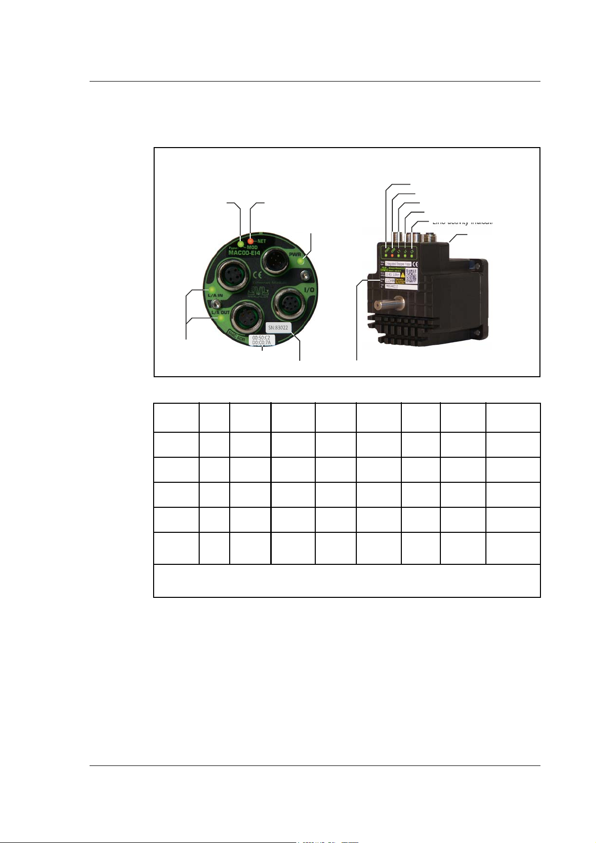
4.4 Commissioning
TT3043-02GB
Hardware serial number
MAC Module Indicators
and label overview
MIS Motor Indicators
and label overview
Line activity
indicators
NETwork status indicator
Power indicator
MODule status indicator
Line activity indicator (CN2)
Line activity indicator (CN3)
MAC address
(placed at front)
NETwork status
indicator
MODule status
indicator
Power
indicator
Hardware serial number
MAC address
4.4.2 Indicator LED’s - description.
The LED's are used for indicating states and faults of module. There is one power LED,
two link/activity LED's (one for each Ethernet connector), and 2 status LED's.
LED indicator descriptions - Covers both MAC and MIS/MIL.
LED Text
MAC / MIx
L/A IN /
L/A OUT /
MOD /
NET /
ERR
PWR Green
Notes:
Blinking: Flashing with equal on and off periods of 200ms (2.5Hz). Flickering: Rapid flashing with a period
of approximately. 50ms (10 Hz).
Colour Constant
L2
L3
L1
Green
Green
Red/
Green
Red/
Green
No valid
Ethernet
connection.
No valid
Ethernet
connection.
No power
applied
No IP
address
Power is not
applied.
off
Constant
on
(Green)
Ethernet is
connected.
Ethernet is
connected.
Module sta-
tus OK
CIP conec-
tion estab-
lished
Power is
applied.
Blinking
(Green)
Module not
configured
No CIP
connection
Constant
on
(Red)
- - - - Activity on line
- - - - Activity on line
Major
module fault
Duplicate IP
address
- - - -
Blinking
(Red)
Minor
module
fault
Connection time-
out
Blinking
(Red/
Green)
Self test in
progress
Self test in
progress
Flickering
Power is applied
to module but no
communication
with motor
-
-
JVL Industri Elektronik A/S - User Manual - Ethernet for MAC and MIS motors 93

4.4 Commissioning
TT3022-02GB
4.4.3 MacTalk Ethernet configuration
The module is by default setup with the following Ethernet configuration:
After adjusting all settings press “Apply and save“
for the settings to take effect and for permanently saving the setup.
Information such as EtherNet/IP firmware version, MAC-address and module status is
displayed in the “Status” -field. Notice that the MAC-address is unique for each module
and can not be changed.
A label at the front plate of the module also indicate the MAC-address.
Basic use of MacTalk is described in the MAC-motor manual (lit. no. LB0047-xxGB)
IfDHCPisenabled,thenmakesureaDHCPserverisavailableonthesamelocalnetwork.
94 JVL Industri Elektronik A/S - User Manual - Ethernet for MAC and MIS motors

4.4 Commissioning
TT3031GB
Explanation
3 - Requested position = 200000
5 - Velocity = 8000 (8000 = 2820 RPM)
6 - Acceleration = 2 Cnt/s² (2 = 543 RPM/s²)
7 - Torque = 512 (512 = 150%)
0 - No Selection (value is not updated)
Setting up IP addresses and general usage of the Rockwell CompactLogix PLC with the
software package Logix5000 is beyond the scope of this example.
The following guideline is based on the JVL MAC400 motor with the factory setup.
1. Apply 24V, open MacTalk and setup the ethernet settings as required and the IO assembly (cyclic data setup) according to the following:
2. Press the “Apply and save” -button for permanent storage of the EthernetIP -settings.
3. Switch off the 24V supply while connecting the Ethernet cable to the switch/PLC.
4. Re-apply 24V set the PLC into “RUN” -mode.Now we should be able to control the
motor.
5. Start by setting the profile data such as, Velocity, acceleration and Torque. According
to the following:
JVL Industri Elektronik A/S - User Manual - Ethernet for MAC and MIS motors 95

4.4 Commissioning
Logix 5000 tag list MacTalk status bar
TT3032GB
6. Now we will set the motor into an active mode (position mode), find the Controller
tag “Mode” enter 2, find the tag “Set_Mode” enter 1. Now the motor is active and
will start moving to the entered position in the “Servo_1:O_Data[0]” which is as
signed to the requested position register in the motor. When the motor reaches the
position it will stop and hold this position.
From MacTalk the actual mode (see the status-panel) is changed from “Passive” to
Position and the motion progress can be followed. Remember to change the “Set_
Mode” tag back to 0 to stop the sending of Msg2 -messages.
-
-
Changing the “Servo_1:O_Data[0]”-tag will result in an immediate repositioning of
the axle in the motor. This value is defined in the IO assembly and is interchanged
cyclic.
To stop the motor set “Mode” = 0 and set “Set_Mode” = 1 to apply the mode setting. Reset “Set_Mode” to 0 again to stop sending Msg2. -messages.
96 JVL Industri Elektronik A/S - User Manual - Ethernet for MAC and MIS motors
7. To activate the explicit message Msg1 set the commanded position to a far greater
value. For example 200000000 as illustrated below.
8. Find the “Read_Pos” -tag and set this to 1. Now the current position of the motor is
seen in the “Actual Position” -tag.

4.4 Commissioning
4.4.4 How to setup a Rockwell RSLogix5000 Project.
After creating a new project in the RSLogix5000 application the JVL motor must be added to the Ethernet bus-system in the project.
This is done by right clicking the “Ethernet-Module” icon in the project manager as illustrated below:
Select “New Module” and the following screen appears:
Expand the “Communications” - list.
JVL Industri Elektronik A/S - User Manual - Ethernet for MAC and MIS motors 97

4.4 Commissioning
TT3048-01GB
TT3049-01GB
Find and select the “Generic Ethernet module”.
Now the module parameter needs to be entered.
Fill in the information as illustrated below:
The IP-address illustrated is the factory default and may be changed according to the lo-
cal settings.
After pressing “Ok” the JVL motor is added to the project and can now be reached by
the PLC.
A demonstration video showing how to set-up the system can be seen using
this link: http://www.jvl.dk
!
98 JVL Industri Elektronik A/S - User Manual - Ethernet for MAC and MIS motors

4.5 Implementation guidelines
4.5.1 Introduction
The following chapters describe the typical usage of the JVL Motor and which registers
to use in the different applications.
The chapter should be considered as a general guideline to get started with the
EthernetIP integration of the JVL Motor.
IMPORTANT!: Please notice that the motor will be active and may start
moving when the mode register (reg. 2) is set to anything than 0 (passive
!
mode). The MAC400, 800, 1500 and 4500 will require AC supply in order
to be active.
JVL Industri Elektronik A/S - User Manual - Ethernet for MAC and MIS motors 99

4.5 Implementation guidelines
The actual velocity is transferred in the 1. word
The 5. word holds the data from the error/status
register. This data is a bitfield structure holding both
motion related information and present error type.
The operation mode is set in the 1. Word,
0=passive mode and 1=Velocity mode.
Use passive mode to stop the motor and
velocity mode to start the motor.
The requested velocity is set in the 3. word
The requested acceleration is set in the 5. word
TT3016GB
4.5.2 Running Velocity control
To use the JVL motor in velocity mode the following registers are basically of interest.
1. “Mode” - Mode register 2
2. “V_SOLL” - Velocity register 5
3. “A_SOLL” - Acceleration register 6
4. “Error/Status” - Error and status register 35
So, to control these registers the assembly object needs to configured.
From MacTalk the setup is configured as this.
With the settings illustrated above we initiate the velocity mode by writing 0x1 to the first
word-value, this is velocity mode.
From the scanner the registers is accessed using the assembly object and accessing the
registers R/W on words 1-5.
1. Set the needed velocity. V_SOLL = V x 2.77 [rpm]
Ex. We need the motor to run with a constant speed of 1200 RPM. So, V_SOLL =
1200/2,77 = 433 counts/sample
2. Set the needed acceleration. A_SOLL = A x 271 [RPM/s²]
Ex. We need the motor to accelerate with 100000 RPM/s² so, A_SOLL = 100000/
271 = 369 counts/sample².
3. Now set the motor into velocity mode and thereby activate the motor.
Ex. The motor needs to be activated by setting it into velocity mode, so we need to
set the mode register to the value 1. Mode = 1 which is velocity mode, now the mo
tor will use the acceleration and the velocity just configured.
Please find a complete list of register descriptions in the appendix.
Motor registers MAC050 - 141, page 264 and Motor registers MAC400 - 4500, page 273 or
Motor registers MISxxx, page 292
-
100 JVL Industri Elektronik A/S - User Manual - Ethernet for MAC and MIS motors
 Loading...