

Jvc XV-N410-B, XV-N412-S Service Manual
SERVICE MANUAL
DVD PLAYER
YD02020047
XV-N410B,XV-N412S
TABLE OF CONTENTS
1 PRECAUTION. . . . . . . . . . . . . . . . . . . . . . . . . . . . . . . . . . . . . . . . . . . . . . . . . . . . . . . . . . . . . . . . . . . . . . . . . 1-3
2 SPECIFIC SERVICE INSTRUCTIONS . . . . . . . . . . . . . . . . . . . . . . . . . . . . . . . . . . . . . . . . . . . . . . . . . . . . . . 1-7
3 DISASSEMBLY . . . . . . . . . . . . . . . . . . . . . . . . . . . . . . . . . . . . . . . . . . . . . . . . . . . . . . . . . . . . . . . . . . . . . . . 1-7
4 ADJUSTMENT . . . . . . . . . . . . . . . . . . . . . . . . . . . . . . . . . . . . . . . . . . . . . . . . . . . . . . . . . . . . . . . . . . . . . . . . 1-7
5 TROUBLESHOOTING . . . . . . . . . . . . . . . . . . . . . . . . . . . . . . . . . . . . . . . . . . . . . . . . . . . . . . . . . . . . . . . . . . 1-7
COPYRIGHT © 2004 Victor Company of Japan, Limited
No.YD020
2004/7
SPECIFICATION
XV-N410B for UJ
Readable discs DVD VIDEO, DVD-R (Video format), DVD-RW (Video format), SVCD, Video CD, Audio CD (CD-DA), CD-R/RW
(CD-DA, SVCD, Video CD, MP3/WMA format, JPEG)
Video format REMOTE, 480i (Interlaced scan)/
480p (Progressive scan) selectable
Power requirements AC 120 V~, 60 Hz AC 110 V - 240 V~, 50 Hz/60 Hz AC 240 V~, 50 Hz
Power consumption 12 W (POWER ON), 2.0 W (STANDBY mode)
Mass 1.9 k g
Dimensions (W × H × D) 435 mm × 44 mm × 258.6 mm
COMPONENT (pin jacks) Y Output: 1.0 Vp-p (75 Ω)
PB/PR Output: 0.7 Vp-p (75 Ω)
VIDEO OUT (pin jack) 1.0 Vp-p (75 Ω)
S-VIDEO OUT (S jack) Y Output: 1.0 Vp-p (75 Ω)
C Output: 286 mVp-p (75 Ω)
Horizontal resolution 500 lines or more
ANALOG OUT (pin jack) 2.0 Vrms (10 kΩ)
DIGITAL OUT (COAXIAL) 0.5 Vp-p (75 Ω termination)
DIGITAL OUT (OPTICAL) -21 dBm to -15 dBm (peak)
Frequency response CD (sampling frequency 44.1 kHz):2 Hz to 20 kHz
DVD (sampling frequency 48 kHz):2 Hz to 22 kHz
(4 Hz to 20 kHz for DTS and Dolby Digital bitstream signals)
DVD (sampling frequency 96 kHz):2 Hz to 44 kHz
Dynamic range 16 bit: More than 98 dB
20 bit/24 bit: More than 100 dB
Wow and flutter Unmeasurable (less than +- 0.002%)
Total harmonic distortion 16 bit: less than 0.008%
20 bit/24 bit: less than 0.008%
XV-N412S for US,UB,UG,UX,UW,UF,UT
General
REMOTE, 525i/625i (Interlaced scan)/525p/625p (Progressive scan) selectable
Other
Video outputs
Audio outputs
Audio characteristics
XV-N412S for A
* Notes for PX model (Check the specification indication on the rear panel.)
Power requirements AC 110 V to 240 V~ , 50 Hz/60 Hz
Power consumption 12 W (POWER ON), 2.0 W(STANDBY mode)
• Manufactured under license from Dolby Laboratories. "Dolby" and the double-D symbol are trademarks of Dolby Laboratories.
• "DTS" and "DTS 2.0+Digital Out" are trademarks of Digital Theater Systems, Inc.
• This product incorporates copyright protection technology that is protected by method claims of certain U.S. patents and other intellectual property rights owned by Macrovision Corporation and other rights owners. Use of this copyright protection technology must be authorized by Macrovision Corporation, and is intended for home and other limited viewing uses only unless otherwise authorized by Macrovision Corporation.
Reverse engineering or disassembly is prohibited.
• “CONSUMERS SHOULD NOTE THAT NOT ALL HIGH DEFINITION TELEVISION SETS ARE FULLY COMPATIBLE WITH THIS PRODUCT
AND MAY CAUSE ARTIFACTS TO BE DISPLAYED IN THE PICTURE. IN CASE OF 525 OR 625 PROGRESSIVE SCAN PICTURE PROBLEMS, IT IS RECOMMENDED THAT THE USER SWITCH THE CONNECTION TO THE “STANDARD DEFINITION” OUTPUT.
IF THERE ARE QUESTIONS REGARDING OUR TV SET COMPATIBILITY WITH THIS MODEL 525p AND 625p DVD PLAYER, PLEASE
CONTACT OUR CUSTOMER SERVICE CENTER.”
Digital output signal chart
Disc type
DVD with 48/44.1 kHz,
16/20/24 bit linear PCM
DVD with 96 kHz, 16/22/24 bit
linear PCM
DVD with DTS 48 kHz, 16 bit, stereo linear PCM DTS bitstream
DVD with Dolby Digital 48 kHz, 16 bit, stereo linear PCM Dolby Digital bitstream
DVD with MPEG Multichannel 48kHz, 16 bit, stereo linear PCM MPEG bitstream
SVCD/Video CD/Audio CD 44.1 kHz, 16 bit, stereo linear PCM
Audio CD with DTS 44.1kHz, 16 bit, stereo linear PCM DTS bitstream
CD-R/RW with MP3/WMA Linear PCM
PCM ONLY DOLBY DIGITAL/PCM STREAM/PCM
48/44.1 kHz, 16 bit, stereo linear PCM
48 kHz, 16 bit, stereo linear PCM (Down sampling)
Output
1-2 (No.YD020)
SECTION 1
PRECAUTION
1.1 Safety Precautions
(1) This design of this product contains special hardware and
many circuits and components specially for safety purposes. For continued protection, no changes should be made
to the original design unless authorized in writing by the
manufacturer. Replacement parts must be identical to
those used in the original circuits. Services should be performed by qualified personnel only.
(2) Alterations of the design or circuitry of the product should
not be made. Any design alterations of the product should
not be made. Any design alterations or additions will void
the manufacturers warranty and will further relieve the
manufacture of responsibility for personal injury or property
damage resulting therefrom.
(3) Many electrical and mechanical parts in the products have
special safety-related characteristics. These characteristics are often not evident from visual inspection nor can the
protection afforded by them necessarily be obtained by using replacement components rated for higher voltage, wattage, etc. Replacement parts which have these special
safety characteristics are identified in the Parts List of Service Manual. Electrical components having such features
are identified by shading on the schematics and by ( ) on
the Parts List in the Service Manual. The use of a substitute
replacement which does not have the same safety characteristics as the recommended replacement parts shown in
the Parts List of Service Manual may create shock, fire, or
other hazards.
(4) The leads in the products are routed and dressed with ties,
clamps, tubings, barriers and the like to be separated from
live parts, high temperature parts, moving parts and/or
sharp edges for the prevention of electric shock and fire
hazard. When service is required, the original lead routing
and dress should be observed, and it should be confirmed
that they have been returned to normal, after reassembling.
(5) Leakage shock hazard testing)
After reassembling the product, always perform an isolation check on the exposed metal parts of the product (antenna terminals, knobs, metal cabinet, screw heads,
headphone jack, control shafts, etc.) to be sure the product
is safe to operate without danger of electrical shock.Do not
use a line isolation transformer during this check.
• Plug the AC line cord directly into the AC outlet. Using a
"Leakage Current Tester", measure the leakage current
from each exposed metal parts of the cabinet, particularly any exposed metal part having a return path to the
chassis, to a known good earth ground. Any leakage current must not exceed 0.5mA AC (r.m.s.).
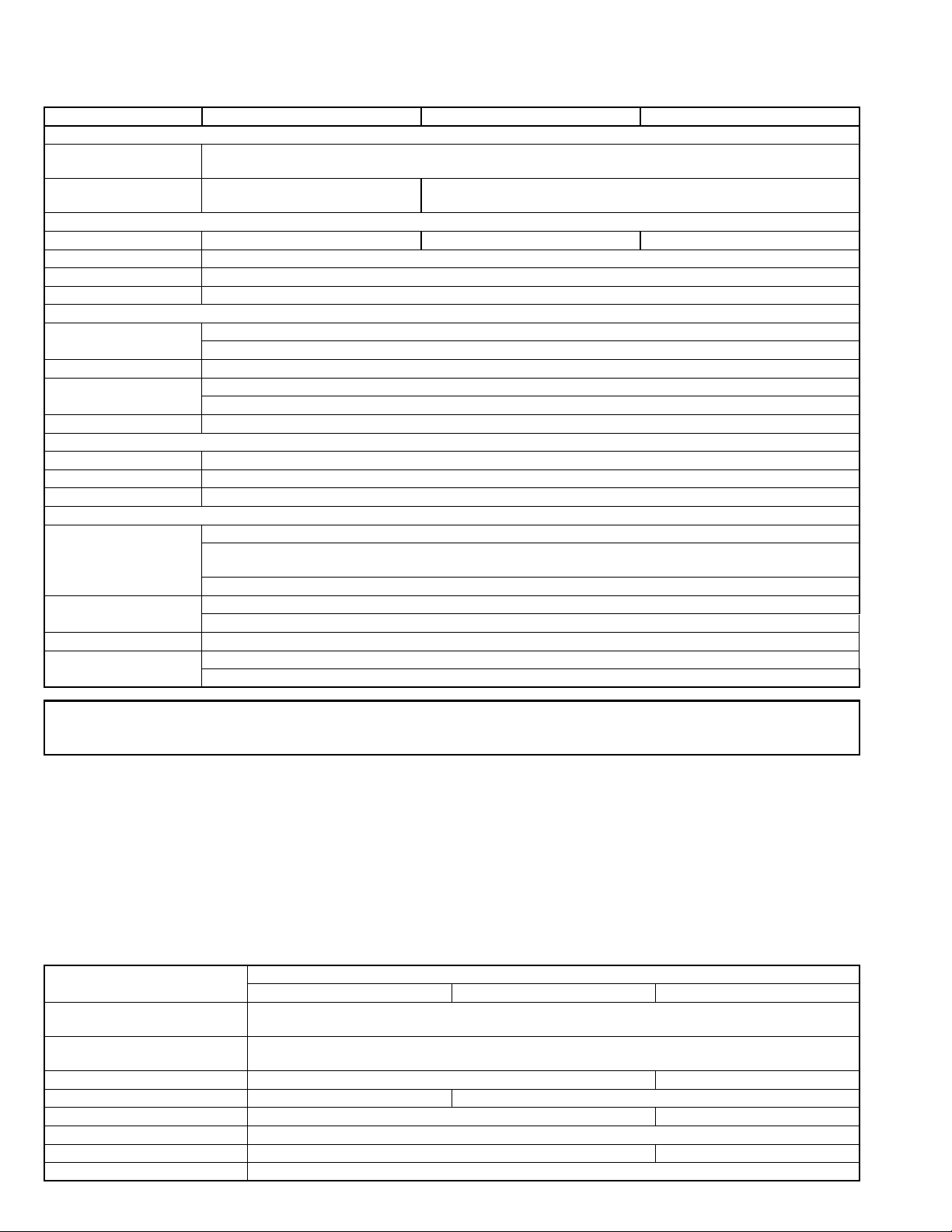
• Alternate check method
Plug the AC line cord directly into the AC outlet. Use an
AC voltmeter having, 1,000 ohms per volt or more sensitivity in the following manner. Connect a 1,500 ohm 10W
resistor paralleled by a 0.15 F AC-type capacitor between an exposed metal part and a known good earth
ground.
Measure the AC voltage across the resistor with the AC
voltmeter.
Move the resistor connection to each exposed metal
part, particularly any exposed metal part having a return
path to the chassis, and measure the AC voltage across
the resistor. Now, reverse the plug in the AC outlet and
repeat each measurement. Voltage measured any must
not exceed 0.75 V AC (r.m.s.). This corresponds to 0.5
mA AC (r.m.s.).
1.2 Warning
(1) This equipment has been designed and manufactured to
meet international safety standards.
(2) It is the legal responsibility of the repairer to ensure that
these safety standards are maintained.
(3) Repairs must be made in accordance with the relevant
safety standards.
(4) It is essential that safety critical components are replaced
by approved parts.
(5) If mains voltage selector is provided, check setting for local
voltage.
1.3 Caution
Burrs formed during molding may be left over on some parts
of the chassis.
Therefore, pay attention to such burrs in the case of preforming repair of this system.
1.4 Critical parts for safety
In regard with component parts appearing on the silk-screen
printed side (parts side) of the PWB diagrams, the parts that are
printed over with black such as the resistor ( ), diode ( )
and ICP ( ) or identified by the " " mark nearby are critical for
safety. When replacing them, be sure to use the parts of the
same type and rating as specified by the manufacturer. (Except
the JC version)
(No.YD020)1-3
1.5 Preventing static electricity
Electrostatic discharge (ESD), which occurs when static electricity stored in the body, fabric, etc. is discharged, can destroy the laser
diode in the traverse unit (optical pickup). Take care to prevent this when performing repairs.
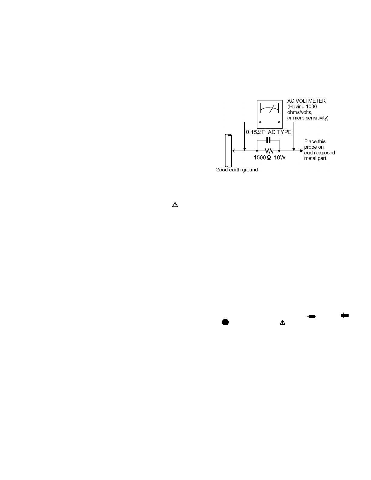
1.5.1 Grounding to prevent damage by static electricity
Static electricity in the work area can destroy the optical pickup (laser diode) in devices such as DVD players.
Be careful to use proper grounding in the area where repairs are being performed.
(1) Ground the workbench
Ground the workbench by laying conductive material (such as a conductive sheet) or an iron plate over it before placing the
traverse unit (optical pickup) on it.
(2) Ground yourself
Use an anti-static wrist strap to release any static electricity built up in your body.
(3) Handling the optical pickup
• In order to maintain quality during transport and before installation, both sides of the laser diode on the replacement optical
pickup are shorted. After replacement, return the shorted parts to their original condition.
(Refer to the text.)
• Do not use a tester to check the condition of the laser diode in the optical pickup. The tester's internal power source can easily
destroy the laser diode.
1.6 Handling the traverse unit (optical pickup)
(1) Do not subject the traverse unit (optical pickup) to strong shocks, as it is a sensitive, complex unit.
(2) Cut off the shorted part of the flexible cable using nippers, etc. after replacing the optical pickup. For specific details, refer to the
replacement procedure in the text. Remove the anti-static pin when replacing the traverse unit. Be careful not to take too long
a time when attaching it to the connector.
(3) Handle the flexible cable carefully as it may break when subjected to strong force.
(4) I t is not possible to adjust the semi-fixed resistor that adjusts the laser power. Do not turn it.
1-4 (No.YD020)
1.7 Important for laser products
(1) CLASS 1 LASER PRODUCT
(2) DANGER : Invisible laser radiation when open and inter
lock failed or defeated. Avoid direct exposure to beam.
(3) CAUTION : There are no serviceable parts inside the
Laser Unit. Do not disassemble the Laser Unit. Replace the
complete Laser Unit if it malfunctions.
(4) CAUTION : The compact disc player uses invisible laser
radiation and is equipped with safety switches which
prevent emission of radiation when the drawer is open and
the safety interlocks have failed or are de feated.
It is dangerous to defeat the safety switches.
VARNING
Osynlig laserstrålning är denna del är öppnad och spårren är
urkopplad. Betrakta ej strålen.
VARO
Avattaessa ja suojalukitus ohitettaessa olet alttiina näkymättömälle lasersäteilylle. Älä katso säteeseen.
ADVARSEL
Usynlig laserstråling ved åbning, når sikkerhedsafbrydere er
ude af funktion. Undgå udsasttelse for stråling.
ADVARSEL
Usynlig laserstråling ved åpning, når sikkerhetsbryteren er avslott. unngå utsettelse for stråling.
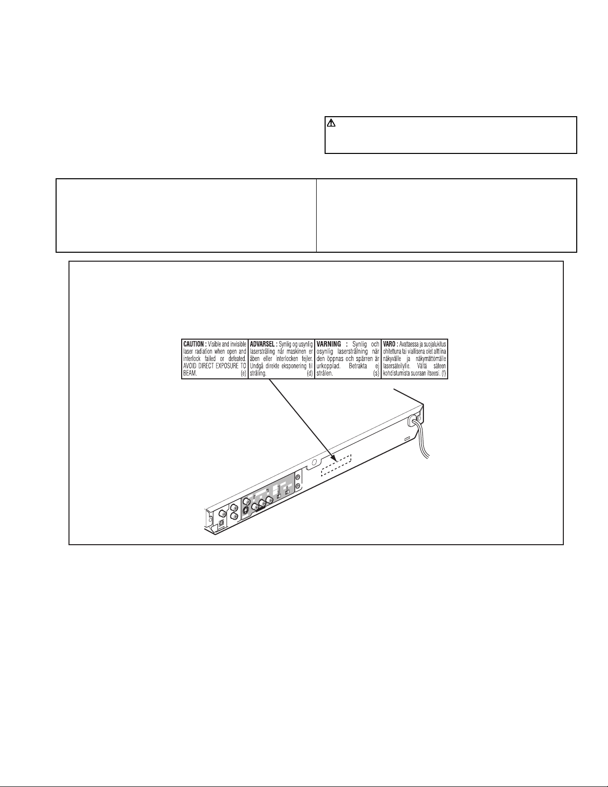
REPRODUCTION AND POSITION OF LABEL and PRINT
WARNING LABEL and PRINT
(5) CAUTION : If safety switches malfunction, the laser is able
to function.
(6) CAUTION : Use of controls, adjustments or performance of
procedures other than those specified herein may result in
hazardous radiation exposure.
CAUTION
Please use enough caution not to see the beam directly
or touch it in case of anadjustment or operation check.
The inside of a rear panel
E
T
O
M
E
C
R
S
p
NT
525
5p
AL
P
/62
T
i
5
2
5
NEN
5i
2
PO
R
P
/6
M
O
C
O
E
ID
B
V
P
Y
T
F
E
L
L
IA
X
A
O
C
/
M
C
P
REAM
T
S
L
A
TIC
L
P
O
A
DIGIT
UT
O
VIDEO OUT
EO
ID
-V
S
T
H
IG
R
OUT
IO
D
AU
K
PU LIN
M
CO
V
A
(No.YD020)1-5
1.8 Precautions for Service
1.8.1 Handling of Traverse Unit and Laser Pickup
(1) Do not touch any peripheral element of the pickup or the actuator.
(2) The traverse unit and the pickup are precision devices and therefore must not be subjected to strong shock.
(3) Do not use a tester to examine the laser diode. (The diode can easily be destroyed by the internal power supply of the tester.)
(4) To replace the traverse unit, pull out the metal short pin for protection from charging.
(5) When replacing the pickup, after mounting a new pickup, remove the solder on the short land which is provided at the center of
the flexible wire to open the circuit.
(6) Half-fixed resistors for laser power adjustment are adjusted in pairs at shipment to match the characteristics of the optical block.
Do not change the setting of these half-fixed resistors for laser power adjustment.
1.8.2 Destruction of Traverse Unit and Laser Pickup by Static Electricity
Laser diodes are easily destroyed by static electricity charged on clothingor the human body. Before repairing peripheral elements of
the traverse unit or pickup, be sure to take the following electrostatic protection:
(1) Wear an antistatic wrist wrap.
(2) With a conductive sheet or a steel plate on the workbench on which the traverse unit or the pick up is to be repaired, ground the
sheet or the plate.
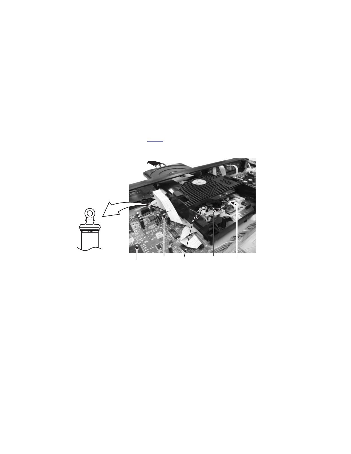
(3) It solders to two short circuit sections on the substrate of a pick-up.
(4) After removing the flexible wire from the connector (CN101
), short-circuit the flexible wire by the metal clip.
(5) Short-circuit the laser diode by soldering the land which is provided at the center of the flexible wire for the pickup.
After completing the repair, remove the solder to open the circuit.
Main board
CN101
Gear1
Short circuit Pick-up
*Please refer to the disassembly method for details.
1-6 (No.YD020)

SECTION 2
SPECIFIC SERVICE INSTRUCTIONS
The following table indicates main different points between models XV-N410B, XV-N412S for North America and XV-N410B, XVN412S for Asia.
Destination North America(No.XA018) Asia (No.YD020)
PAL/NTSC selector NOT USED USED (except UJ)
VIDEO Signal selector 480i - 480p - REMOTE 525i/625i - 525p/625p - REMOTE
SECTION 3
DISASSEMBLY
Please refer to "XV-N410B, XV-N412S No.XA018" about this section.
SECTION 4
ADJUSTMENT
Please refer to "XV-N410B, XV-N412S No.XA018" about this section.
SECTION 5
TROUBLESHOOTING
Please refer to "XV-N410B, XV-N412S No.XA018" about this section.
(No.YD020)1-7

Victor Company of Japan, Limited
AV & MULTIMEDIA COMPANY DIGITAL VIDEO STORAGE CATEGORY 12, 3-chome, Moriya-cho, kanagawa-ku, Yokohama, kanagawa-prefecture, 221-8528, Japan
(No.YD020)
Printed in Japan
WPC
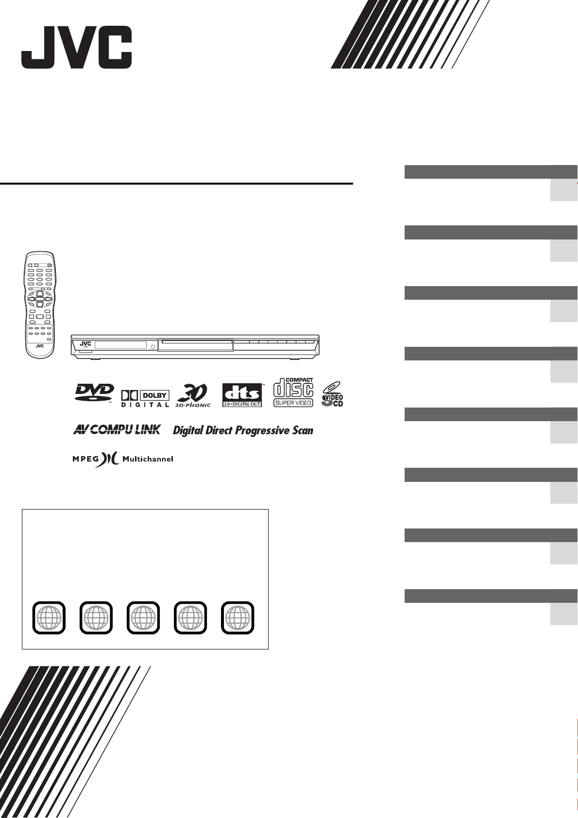
DVD PLAYER
XV-N412S
VIDEO
Before operation
15
Preparations 4
Basic playback 8
Various kinds of playback 11
MP3/WMA disc playback 20
2
Region code of DVD VIDEO
DVD players and DVD VIDEO discs have their own Region Code
numbers. This player can play back DVD VIDEO discs whose
Region Code numbers include the player’s Region Code, which is
indicated on the region code symbol on the rear panel.
Example of playable DVD VIDEO discs when the player’s Region
Code is “2”:
2
ALL
2
52
4
3
1
2
3
1
5
6
4
INSTRUCTIONS
JPEG disc playback 22
Changing the initial settings 24
Additional information 29
GNT0044-017A
[US/UB/UG/UX/UW/A]
Warnings, Cautions and Others
CAUTION
To reduce the risk of electrical shocks, fire, etc.:
1. Do not remove screws, covers or cabinet.
2. Do not expose this appliance to rain or moisture.
Caution –– STANDBY/ON button!
Disconnect the mains plug to shut the power off completely
(the STANDBY/ON lamp goes off).
The STANDBY/ON button in any position does not
disconnect the mains line.
• When the unit is on standby, the STANDBY/ON lamp lights
red.
• When the unit is turned on, the STANDBY/ON lamp lights
green.
The power can be remote controlled.
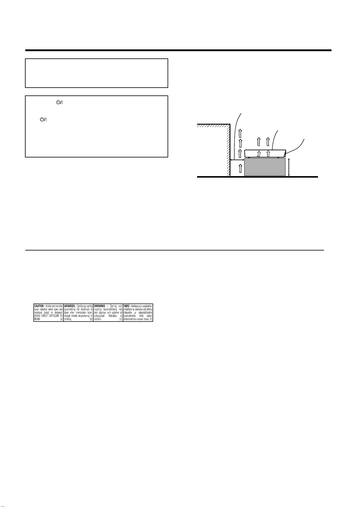
Caution: Proper Ventilation
To avoid risk of electric shock and fire and to protect from damage,
locate the apparatus as follows:
Front: No obstructions and open spacing.
Sides: No obstructions in 3 cm from the sides.
Top: No obstructions in 5 cm from the top.
Back: No obstructions in 15 cm from the back.
Bottom: No obstructions, place on the level surface.
Spacing 15 cm or more
XV-N412S
Front
Wall or
obstructions
CAUTION
• Do not block the ventilation openings or holes.
(If the ventilation openings or holes are blocked by a newspaper or
cloth, etc., the heat may not be able to get out).
• Do not place any naked flame sources, such as lighted candles, on
the apparatus.
• When discarding batteries, environmental problems must be
considered and local rules or laws governing the disposal of these
batteries must be followed strictly.
• Do not expose this apparatus to rain, moisture, dripping or
splashing and that no objects filled with liquids, such as vases,
shall be placed on the apparatus.
IMPORTANT FOR LASER PRODUCTS
1. CLASS 1 LASER PRODUCT
2. CAUTION: Do not open the top cover. There are no user
serviceable parts inside the unit; leave all servicing to qualified
service personnel.
3. CAUTION: Visible and invisible laser radiation when open and
interlock failed or defeated. Avoid direct exposure to beam.
4. REPRODUCTION OF LABEL: CAUTION LABEL, PLACED
INSIDE THE UNIT.
Stand height
5 cm or more
Floor
G-1

Supplied accessories
Check that you have all the following accessories supplied to you.
If anything is missing, consult your dealer immediately.
• Audio/video cable (Yellow/White/Red) (× 1)
• Remote control unit (× 1)
• R6P(SUM-3)/AA(15F) battery (× 2)
• AC power plug adaptor (× 1) (except for Australia and
Hongkong models)
Table of contents
Supplied accessories................................................................1
About this manual .....................................................................1
Precautions ................................................................................ 1
Before operation................................................... 2
About discs ..............................................................................2
Names of parts and controls....................................................3
About this manual
• The display window information and OSD (On Screen Display)
menu items are put in brackets [ ] in the operation procedures.
• Usable disc(s) for each operation/function is (are) referred to by
the icons;
Precautions
Notes on the power cord
• When you are away on travel or otherwise for an extended
period of time, remove the plug from the wall outlet. A small
amount of power (2.0 W) is always consumed while the power
cord is connected to the wall outlet.
• When unplugging the unit from the wall outlet, always pull the
plug, not the power cord.
• Do not handle the power cord with wet hands!
Avoid moisture, water and dust
• Do not place the unit in moist or dusty places.
• If water gets inside the unit, turn off the power and remove the
plug from the wall outlet, then consult your dealer. Using the
unit in this state may cause a fire or electrical shock.
Avoid high temperatures
• Do not expose the unit to direct sunlight or place it near a
heating device.
Notes on installation
• Select a place which is level, dry and neither too hot nor too
cold between 5°C and 35°C.
• Leave sufficient distance between the player and the TV.
• Do not install the player in a place subject to vibrations.
• Do not put heavy objects on the player.
To prevent malfunction of the unit
• There are no user-serviceable parts inside. If anything goes
wrong, unplug the power cord and consult your dealer.
• Do not insert any metallic objects, such as wires, hairpins,
coins, etc. into the player.
• Do not block the vents. Blocking the vents may damage the
player.
To clean the cabinet
• Use a soft cloth. Follow the relevant instructions on the use of
chemically-coated cloths.
• Do not use benzene, thinner or other organic solvents and
disinfectants. These may cause deformation or discoloring.
Preparations ......................................................... 4
Connections............................................................................. 4
Using the remote control unit................................................... 7
Basic playback ..................................................... 8
Turning the player on and off................................................... 8
Initial setup ..............................................................................8
Starting playback .....................................................................9
Restarting playback after stopping (resuming playback) ....... 10
Various kinds of playback ................................. 11
Playback at various speeds................................................... 11
Locating the beginning of a scene or song ............................ 12
Playing from a specific position .............................................12
Changing the playback order.................................................13
Repeat playback.................................................................... 15
Changing the language, sound and scene angle ..................15
Special picture and sound effects.......................................... 16
Menu bar functions ................................................................18
MP3/WMA disc playback ................................... 20
Operations .............................................................................20
JPEG disc playback ........................................... 22
About JPEG discs.................................................................. 22
Basic operations ....................................................................22
Viewing pictures continuously (slide show mode) .................23
Changing the initial settings ............................. 24
Selecting preferences............................................................ 24
Limiting playback by children................................................. 27
Additional information ....................................... 29
AV COMPU LINK remote control system ..............................29
Troubleshooting..................................................................... 30
Specifications ........................................................................31
Appendix A: Digital output signal chart .................................. 31
Appendix B: Country/Area code list for Parental Lock........... 32
Appendix C: Table of languages and their abbreviations ......32
Appendix D: Glossary............................................................ 33
1
B
e
f
o
r
e
o
p
e
r
a
t
i
o
n
Before operation
About discs
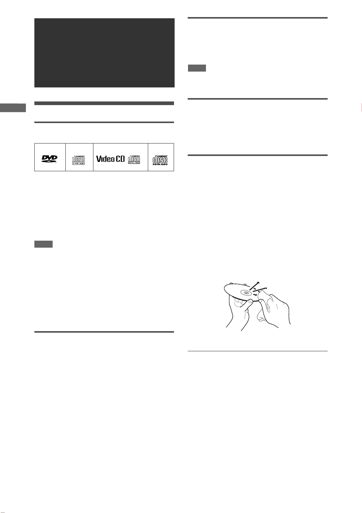
Playable disc types
Discs with the following marks can be played back on the player.
DVD VIDEO SVCD Video CD
Audio CD
Digital audio formats
The player supports the following digital audio formats (see page
33 “Glossary” for descriptions of each audio format):
Linear PCM, Dolby Digital, DTS (Digital Theater Systems),
MPEG Multichannel
NOTE
Depending on the player’s [DIGITAL AUDIO OUTPUT] setting,
digital audio signals may not be output as they are recorded on
the disc. See “DIGITAL AUDIO OUTPUT” on page 26 for details.
Notes on discs
• With some DVD VIDEO discs, the player starts playback
automatically after inserting the disc.
• The image may be sometimes poor or noisy due to defects in
the disc itself.
• With some discs, operations described in this manual may not
be possible.
VIDEO
The DVD Logo is a trademark.
The player can also play back the following discs:
• DVD-R and DVD-RW discs written in the DVD VIDEO format
and finalized
• CD-R and CD-RW discs written in the SVCD, Video CD or
Audio CD format and finalized
• CD-R and CD-RW discs written in MP3 or WMA in accordance
with the “ISO 9660” format (See page 20 for details.)
• CD-R and CD-RW discs written in JPEG in accordance with the
“ISO 9660” format (See page 22 for details.)
NOTE
If a disc gets dirty, scratched or warped, or due to the disc
characteristics or recording conditions, it may take considerable
time for the unit to read the content, or the unit may not be able to
play back such discs.
The player can play back audio signals recorded in MIX-MODE
CD, CD-G, CD-EXTRA and CD TEXT.
Color system format
This player is compatible with the PAL and NTSC systems. You
can select “PAL” or “NTSC” while using the PAL/NTSC selector
on the rear panel.
Unplayable discs
The player does not play back discs listed below. If you try to play
back these discs, noise may be generated, causing damage to
speakers.
• DVD-RW discs written in the VR format
• DVD-ROM, DVD-RAM, DVD AUDIO, CD-ROM, PHOTO CD,
SACD
Care and handling of discs
If a disc gets dirty, dusty, scratched or warped, playback sound
and picture may be deteriorated. Take proper precautions when
handling discs.
Handling
• Do not touch the surface of the disc.
• Do not damage, stick paper to, or use any adhesive on either
the label side or playback side.
Storing discs
• Keep discs in their cases. If discs are piled on top of one
another without their protective cases, they can be damaged.
• Do not put discs in a location where they may be exposed to
direct sunlight, or where the humidity or temperature is high.
Avoid leaving discs in a car!
Cleaning discs
• Wipe with a soft dry cloth, moving from the center outwards. If a
disc is difficult to clean, wipe with a cloth moistened with water.
• Never use record cleaners, petrol, alcohol or any anti-static
agents.
Notes on copyright
Check the copyright laws in your country before recording from
DVD VIDEO, SVCD, Video CD, Audio CD, MP3, WMA and JPEG
discs.
Recording of copyrighted material may infringe copyright laws.
In addition, the player does not play:
• Unfinalized discs.
• Discs of irregular shape or discs with tape, seals or paste on
either the label side or playback side. Playing back these discs
may damage the player.
2
B
e
f
o
r
e
o
p
e
r
a
t
i
o
n
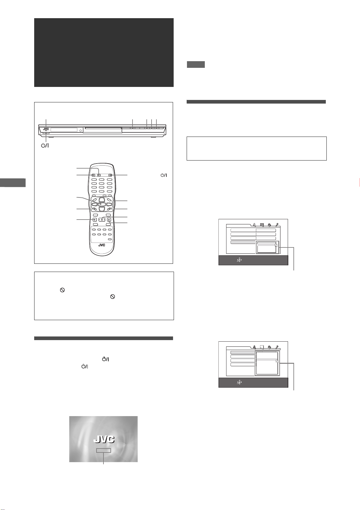
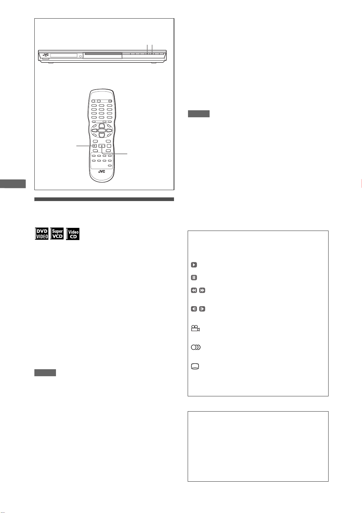
Names of parts and controls
0 -
5768
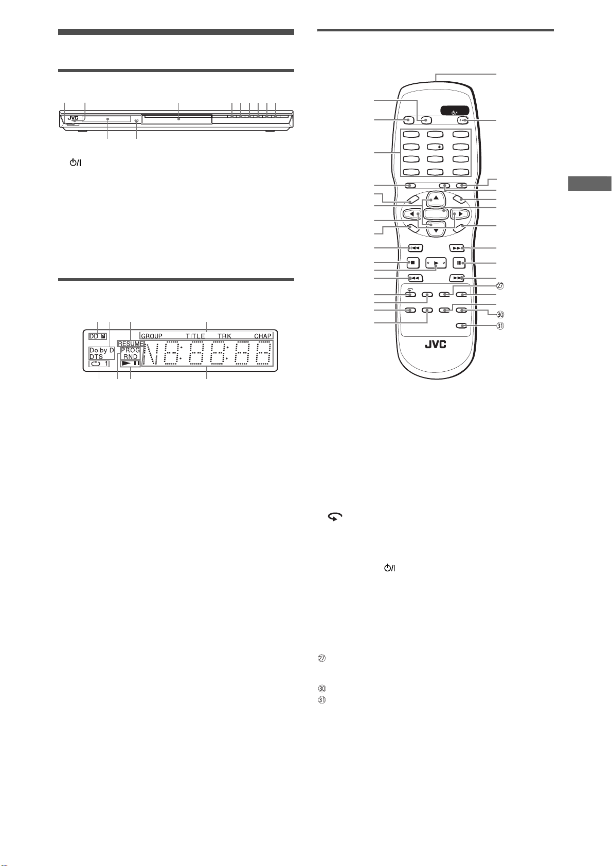
Remote control unit
Front panel
21
1 STANDBY/ON button (8)
2 STANDBY/ON indicator (8)
3 Disc tray (9)
4 0 button (9)
5 4 button (11, 12, 22)
6 ¢ button (11, 12, 22)
7 7 button (9, 10)
8 3 button (9, 10, 11)
9 8 button (9, 11)
0 Display window (see the illustration below)
- Remote sensor (7)
3 45 6 7 8 9
Display window
2143
$
1
OPEN
2
/CLOSE
3
4
5
6
7
8
E
M
P
O
T
S
E
T
U
P
9
0
=
~
!
@
SLOW
ANGLE
#
STANDBY/ON
DISPLAY
213
546
879
010 +10
TITLE/GROUP CANCELRETURN
U
N
-
3D PHONIC
SUB TITLE
ENTER
M
E
N
U
N
E
E
R
C
S
N
O
NEXTPREVIOUS
SELECTCLEAR
SLOW+
VFP
REPEAT
PROGRESSIVE
SCAN
ZOOM
AUDIO
DIMMER
%
^
&
*
(
)
_
+
¡
£
¢
1 Progressive mode indicators
[P] turns on in the progressive scanning mode.
[DDP] turns on depending on the [PICTURE SOURCE]
preference setting and the source type of the current DVD
VIDEO disc (see page 5 for details).
2 Dolby Digital/DTS indicators
[Dolby D] turns on when playing back a Dolby Digital sound
source. [DTS] turns on when playing back a DTS-encoded
digital sound source.
3 Resume indicator
Turns on when playback is interrupted with the resume
function activated.
4 Group/title/track/chapter indicators
Show what is indicated by the multi-information display during
playback.
5 Repeat mode indicator
Turn on in the repeat playback mode and shows the currently
selected repeat mode.
6 Program/random indicators
Turn on in the program playback mode/random playback
mode respectively.
7 3 (play)/8 (pause) indicators
Turn on in the playback mode/pause mode respectively.
8 Multi-information window
Indicates various kinds of information by numbers and
alphabets, such as the player’s current status (“READ,”
“OPEN,” etc.) or currently played DVD’s title and chapter
number.
1 DISPLAY button (9)
2 OPEN/CLOSE button (9)
3 Numeric buttons
4 RETURN button (12)
5 TOP MENU button (12)
6 Cursor selection (5 Up, ∞ Down) buttons
7 Cursor selection (2 Left, 3 Right) buttons
8 SET UP button (9, 24)
9 4/PREVIOUS button (11, 12, 22, 23)
0 7/CLEAR button (9, 10, 14, 15, 20, 21, 22, 23)
- 3/SELECT button (9, 10, 11, 14, 20, 21, 23)
= 1/SLOW– button (11)
~ button (11)
! 3D PHONIC button (17)
@ ANGLE button (16)
# SUBTITLE button (15)
$ Infrared signal window (7)
% STANDBY/ON button (8)
^ CANCEL button (14)
& TITLE/GROUP button (13, 21, 23)
* MENU button (12, 22, 23)
( ENTER button
) ON SCREEN button (9, 13, 14, 15, 18, 21, 23)
_ ¢/NEXT button (11, 12, 22, 23)
+ 8 button (9, 11, 20, 23)
¡ ¡/SLOW+ button (11)
REPEAT button (15, 21, 23)
£ VFP - PROGRESSIVE SCAN button (5, 17)
¢ AUDIO button (16)
ZOOM button (16, 23)
DIMMER button
Press to change the brightness of the display window.
You can select the display window brightness from three levels
or off. If the brightness is set to off, nothing will be shown on
the display.
By pressing this button, the brightness of the blue illumination
around the disc tray also changes.
3
P
r
e
p
a
r
a
t
i
o
n
s
Preparations
Before making connections
• Do not connect the AC power cord until all other
connections have been made.
• Connect VIDEO OUT of the player directly to the video
input of your TV. Connecting VIDEO OUT of the player to a
TV via a VCR may cause a monitor problem when playing
back a copy-protected disc. You may also have a monitor
problem when connecting the player to an integrated TV/
Video system.
NOTE
If your TV has an AV COMPU LINK terminal, you can use the AV
COMPU LINK function. See “AV COMPU LINK remote control
system” on page 29 for details.
Connections
Before using the player, connect the player to a TV and/or
amplifier.
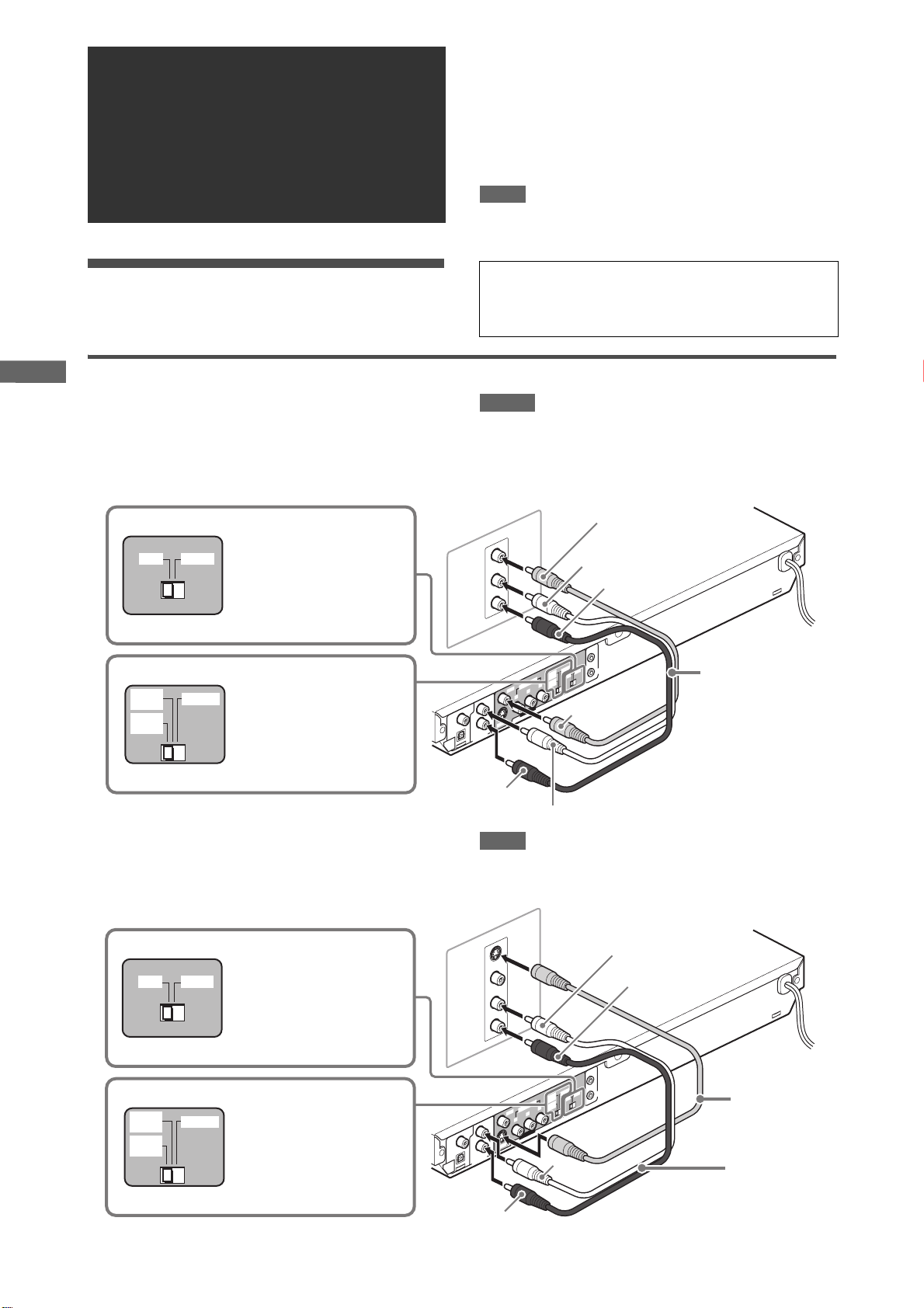
Connecting to a TV
The following sections A to C describe TV connections where
only a TV is connected to the player so that you will hear audio
from the TV.
A Connecting to a conventional TV
Set the PAL/NTSC selector to
Set the PAL/NTSC selector to
“PAL” or “NTSC” to match the
PAL NTSC
525P
/625P
/625i
REMOTE
525i
“PAL” or “NTSC” to match the
color system of your TV.
color system of your TV.
(Change the selector position
(Change the selector position
in stop mode or with no disc
in stop mode or with no disc
inserted.)
inserted.)
Set the 525i/625i - 525p/625p REMOTE selector to “525i/
625i.”
• In the following description, “TV” may be substituted with
“monitor” or “projector.”
• Terminal names used for other components may be different
from those used in the following description.
NOTES
• Do not connect an S-video cable to the S-VIDEO output of the
player. If you do so, you will not be able to obtain correct signals
from the VIDEO jack of the player.
• If your TV has a monaural audio input instead of stereo, you
need to use an optional audio cable which converts stereo
audio output to monaural.
p
5
p
5
i
5
i
5
E
T
O
M
E
R
L
A
P
Ye l l o w
C
S
T
N
Yellow
White
COMPU LINK
AV
Red
TV
IN
VIDEO
LEFT
AUDIO
RIGHT
2
5
2
/6
2
5
2
R
P
/6
COMPONENT
O
E
ID
B
V
P
Y
T
F
E
L
L
IA
X
A
O
C
/
M
C
P
M
EA
R
T
S
L
A
IC
T
AUD
P
O
DIGITAL
OUT
IO OUT
VIDEO OUT
O
E
ID
-V
S
T
H
IG
R
The player
Audio/video
cable (supplied)
B Connecting to a TV with an S-video jack
If your TV has an S-VIDEO input, you can get better picture
quality by connecting it with the S-VIDEO output of the player
using an S-video cable instead of connecting the video input of
the TV to the VIDEO jack of the player.
Set the PAL/NTSC selector to
PAL NTSC
525P
/625P
525i
/625i
REMOTE
“PAL” or “NTSC” to match the
color system of your TV.
(Change the selector position
in stop mode or with no disc
inserted.)
Set the 525i/625i - 525p/625p REMOTE selector to “525i/
625i.”
Red
White
NOTE
To obtain correct signals from the S-VIDEO output, do not
connect cables to the VIDEO jack and COMPONENT VIDEO
OUT jacks of the player.
TV
IN
S-VIDEO
VIDEO
LEFT
AUDIO
RIGHT
T
O
M
E
R
p
5
2
5
p
5
P
2
/6
i
5
2
5
i
5
2
R
P
/6
COMPONENT
O
E
ID
B
V
P
Y
T
F
E
L
L
IA
X
A
O
C
/
M
C
P
M
A
E
TR
S
L
A
IC
T
AUD
P
O
DIGITAL
OUT
IO OUT
VIDEO OUT
O
E
ID
-V
S
T
H
IG
R
White
White
The player
Red
E
COMPU LINK
C
S
T
AV
N
L
A
Red
S-video cable
(not supplied)
Audio cable
(not supplied)
4
P
r
e
p
a
r
a
t
i
o
n
s
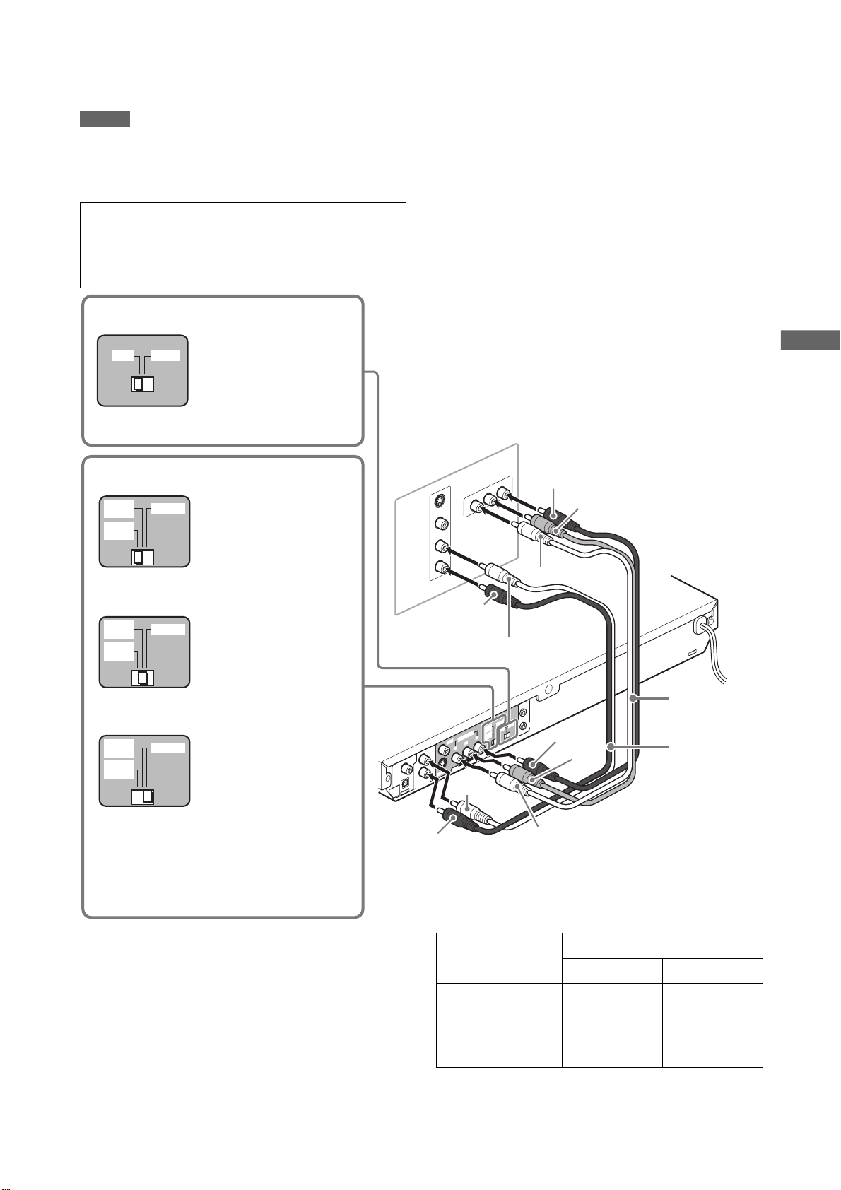
C Connecting to a TV with component jacks
You can enjoy picture of high-fidelity color reproduction by
connecting the COMPONENT VIDEO OUT jacks on the player to
your TV.
NOTES
• Connect “Y” to “Y,” “PB” to “PB” (CB), “PR” to “PR” (CR) correctly.
• When using the COMPONENT VIDEO OUT jacks, do not
connect the S-VIDEO output jack on the player.
• If your TV has component video input jacks of BNC type, use an
adapter which converts a pin jack to a BNC jack (not supplied).
Progressive scan video playback available
In the Progressive scanning mode, you can enjoy high quality
picture with less flickers when the COMPONENT VIDEO OUT
jacks are connected to a TV or monitor that supports the
progressive video input.
Set the PAL/NTSC selector to
PAL NTSC
“PAL” or “NTSC” to match the
color system of your TV.
(Change the selector position
in stop mode or with no disc
inserted.)
Hint
Depending on the source material format, DVD VIDEO discs can
be classified into two types; film source and video source (note
that some DVD VIDEO discs contain both film source and video
source). Film sources are recorded as 24-frame-per-second
information, while (NTSC) video sources are recorded as 30frame-per-second (60-field-per-second interlaced) information.
When the player plays back a film source material, Progressive
(uninterlaced) signals are created using the original information.
When a video source material is played back, the unit interleaves
lines between the interlaced lines on each to create the
interpolated picture and outputs as the progressive signal.
Selecting the 525i/625i - 525p/625p - REMOTE
selector position
525P
/625P
525i
/625i
REMOTE
If your TV equipped with
component jacks does not
support the progressive
scanning mode:
Set the 525i/625i - 525p/625p REMOTE selector to “525i/
625i.”
525P
/625P
525i
/625i
REMOTE
• If your TV equipped with
component jacks supports
the progressive scanning
mode:
Set the 525i/625i - 525p/
625p - REMOTE selector to
“525p/625p.”
525P
/625P
525i
/625i
REMOTE
• If you want to select the
scanning mode between the
interlace and progressive
modes (depending on the
source condition, or when
connecting more than one TV,
etc.):
Set the 525i/625i - 525p/
625p - REMOTE selector to
“REMOTE.”
Thus you can select the mode
from the remote control unit.
TV
Red
R
Y
COMPON
P
B
P
T IN
EN
Blue
Green
S-VID
VID
A
UDIO
EO
E
LEFT
RIGHT
IN
O
The player
Red
White
Component
E
T
O
M
COMPU LINK
E
C
R
S
T
AV
p
N
5
2
5
p
L
5
A
P
2
/6
i
5
2
5
i
5
2
R
P
/6
COMPONENT
O
E
ID
B
V
P
Y
T
F
E
L
L
IA
X
A
O
C
/
M
C
P
M
EA
R
T
S
L
A
IC
T
AUD
P
O
DIGITAL
OUT
IO OUT
VIDEO OUT
O
E
ID
-V
S
T
H
IG
R
White
Red
Red
Blue
Green
video cable
(not supplied)
Audio cable
(not supplied)
Activating the Progressive scanning mode using the remote
control unit
When the player is turned on and the 525i/625i - 525p/625p REMOTE selector is set to “REMOTE,” press and hold down VFP
- PROGRESSIVE SCAN for a few seconds.
The scanning mode switches between the Progressive scanning
and Interlaced scanning modes.
When the scanning mode is set to the Progressive mode, the [P]
indicator lights up in the display window.
[DD] also turns on when Progressive scanned signals on a DVD
VIDEO disc are directly output as they are from the player.
Setting of [PICTURE
SOURCE]
Source type of DVD VIDEO
Film source Video source
AUTO [DD P] [P]
FILM [DDP] [DDP]
VIDEO (NORMAL)/
(ACTIVE)
[P] [P]
Depending on the [PICTURE SOURCE] preference display and
whether the current DVD VIDEO disc is film-source or videosource, the indicator that lights up in the display window differs,
as shown in the table below.
5
P
r
e
p
a
r
a
t
i
o
n
s
NOTES
• The Progressive scanning mode works only when you connect
the player’s COMPONENT VIDEO OUT jacks to your TV.
• There are some progressive TV and High-Definition TV sets
that are not fully compatible with the player, resulting in the
unnatural picture when playing back a DVD VIDEO disc in the
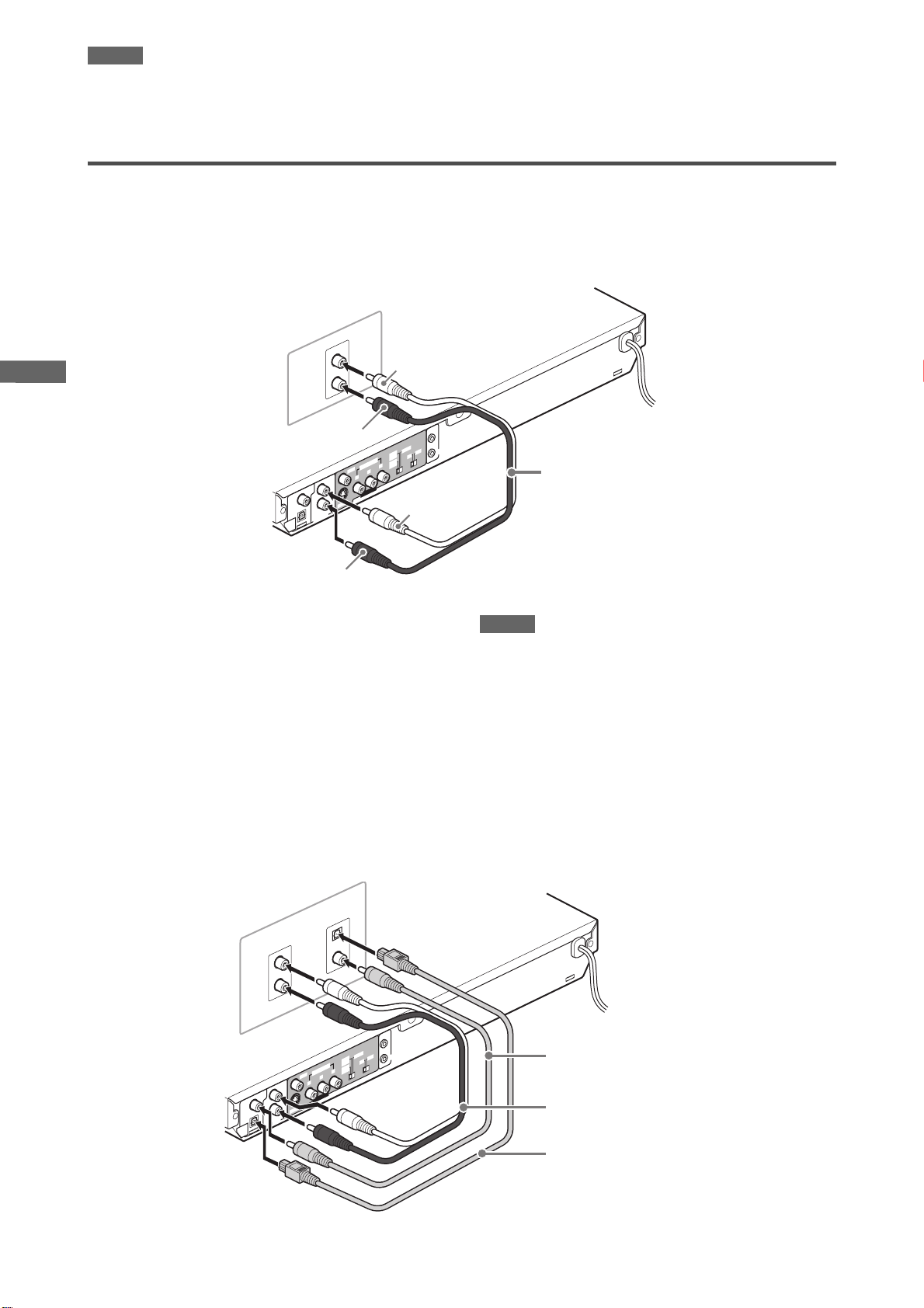
Connecting to optional audio equipment
Connecting to a stereo audio amplifier/receiver
Connect the player’s AUDIO OUT (LEFT/RIGHT) jacks to any
line-level inputs (such as AUX, DVD, CD, etc.) of an audio
amplifier or receiver.
Amplifier or receiver
IN
AUDIO
LEFT
RIGHT
White
Progressive scanning mode. In such a case, use the Interlaced
scanning mode. To check the compatibility of your TV set,
contact your local JVC customer service center.
• All JVC progressive TV and High-Definition TV sets are fully
compatible with the player (Example: AV-61S902).
The player
Red
COMPONENT
O
E
ID
V
YP
T
F
E
L
L
IA
X
A
O
C
/
M
C
P
M
A
E
TR
S
L
A
IC
T
AUDIO OUT
P
O
DIGITAL
OUT
VIDEO OUT
O
E
ID
V
-
S
T
H
IG
R
E
T
O
M
E
C
R
S
T
p
N
5
2
5
p
L
5
A
P
2
/6
i
5
2
5
i
5
2
R
P
/6
B
White
Red
Connecting to a digital audio device
You can enjoy sound of enhanced quality by connecting the
player’s DIGITAL OUT (either OPTICAL or COAXIAL) jack to a
digital input of an amplifier, etc., using an optical or coaxial digital
cable. The digital audio signal on a disc will be transferred directly
from the player. If the connected digital audio equipment is a
Dolby Digital or DTS decoder or an amplifier with a built-in
decoder, you can enjoy high-quality surround sound.
COMPU LINK
AV
Audio cable (not supplied)
NOTES
• Connect the player and the digital audio device by using either
an optical digital cable or a coaxial digital cable.
• It is not recommended to use the digital jacks for dubbing.
When recording the sounds (DVD VIDEO, SVCD, Video CD or
Audio CD) played back on the player, record them through the
analog jacks.
• Depending on the disc, no signal may be output from the
DIGITAL OUT. Make an analog connection in this case.
• Set [DIGITAL AUDIO OUTPUT] in the [AUDIO] preference
display correctly according to the connected digital audio
equipment. If setting made for [DIGITAL AUDIO OUTPUT] is
incorrect, loud noise may be generated causing damage to
the speakers (see page 26).
Digital equipment
IN
OPTICAL
IN
ITAL
DIG
IO OUT
COAXIAL
E
T
O
M
COMPU LINK
E
C
R
S
T
AV
p
N
5
2
5
p
L
5
A
P
2
/6
i
5
2
5
i
5
2
R
P
/6
COMPONENT
O
E
ID
B
V
YP
T
F
E
L
VIDEO OUT
O
E
ID
-V
S
T
H
IG
R
Coaxial digital cable (not supplied)
Audio cable (not supplied)
Optical digital cable (not supplied)
LEFT
DVD
RIGHT
The player
L
IA
X
A
O
C
/
M
C
P
M
A
E
TR
S
L
A
IC
T
AUD
P
O
DIGITAL
OUT
6
P
r
e
p
a
r
a
t
i
o
n
s
Connecting the power cord
When all the audio/video connections have been made, connect
the AC power plug to the wall outlet. Make sure that the plugs are
inserted firmly.
The STANDBY/ON indicator lights in red.
Warning
• Disconnect the power cord:
- if you are not going to use the player for a long time.
- before cleaning the player.
- before moving the player.
• Do not:
- connect or disconnect the power cord with wet hands.
- pull the power cord when disconnecting it, as this may
damage the cord and cause fire, electric shock, or other
accidents.
Caution
• Do not alter, twist or pull the power cord, or put anything heavy
on it, which may cause fire, electric shock, or other accidents.
• If the cord is damaged, consult a dealer and have the power
cord replaced with a new one.
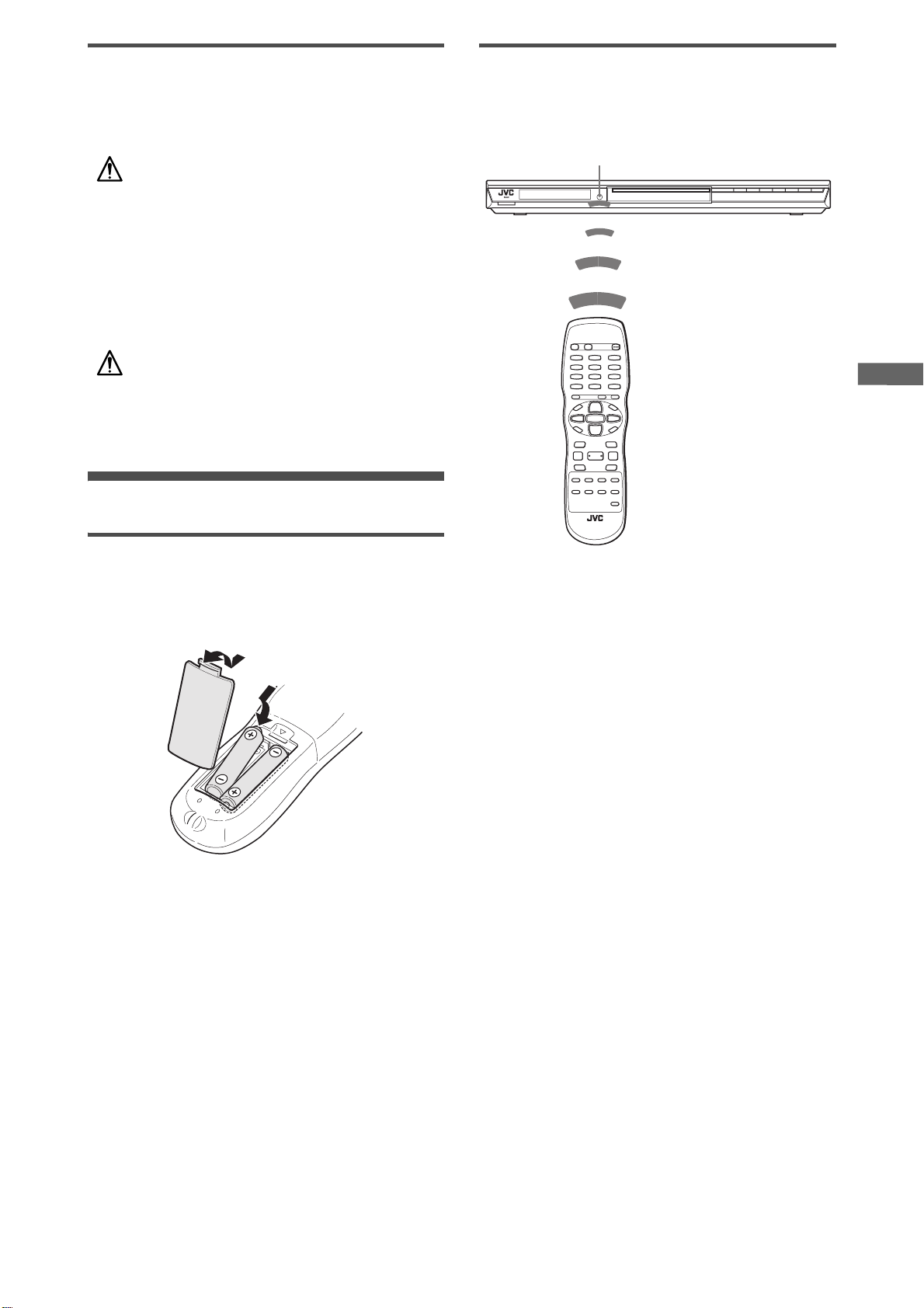
Using the remote control unit
Remote sensor
Point the top of the remote control unit toward the remote sensor
as directly as possible. If you operate it from a diagonal position,
the operating range (approx. 5 m) may be shorter.
Remote sensor
To install batteries
Open the compartment cover, and place the two supplied R6P
(SUM-3)/AA(15F) batteries in the remote control unit according to
the polarity markings (“+” and “–”) inside the compartment. Then
replace the cover.
The batteries will last about six months with normal use.
If the functions of the remote control unit become erratic, replace
the batteries.
Precautions of the safe use of batteries
Observe the following precautions for the safe use of batteries. If
they are used improperly their lives will be shortened, they may
burst or their contents may leak.
• Remove the batteries from the remote control unit if it is not
going to be used for a long period of time.
• Remove dead batteries and dispose of them properly.
• Never leave dead batteries lying around, take them apart, mix
them with other refuse, or throw them into an incinerator.
• Never touch liquid that has leaked out of a battery.
• Do not mix new and old batteries, or batteries of different types,
when replacing them.
7
B
a
s
i
c
p
l
a
y
b
a
c
k
Basic playback
• NOW READING (The player is reading the disc information.)
• REGION CODE ERROR! (The region code of the DVD VIDEO
disc does not match the player. The disc cannot be played
back.)
• OPEN (The disc tray is opening.)
• CLOSE (The disc tray is closing.)
• NO DISC (No disc is loaded.)
NOTE
Even if you turn off the player, the player is not disconnected from
the AC power source as long as it is connected to the wall outlet.
This state is called standby mode. In this state, the player
consumes a very small amount of power.
STANDBY/ON indicator
7380
STANDBY/ON
DISPLAY
OPEN/CLOSE
ENTER
SET UP
7
About invalid operation icon
When you press a button, and if the player does not accept its
operation, appears on your TV screen. Operations are
occasionally unacceptable even if is not displayed.
Note that some operations may not be accepted. For example,
some discs may not allow rapid advance/reverse or slowmotion playback.
STANDBY/ON
5/∞/2/3
ON SCREEN
3 (SELECT)
8
Initial setup
When you turn on the player for the first time after purchase, the
following message appears on the TV screen.
EXECUTE DVD PLAYER SETUP? - BASIC PICTURE/AUDIO
SETTING
YES - PRESS ENTER NO - PRESS CANCEL
You can set the display language, TV monitor type and digital
output before using the player, by following the procedure below.
1
Press ENTER.
The first page of the DVD PLAYER SET UP display appears.
The pull-down menu of the [ON SCREEN LANGUAGE] is
already open.
DVD PLAYER SET UP
MENU LANGUAGE
AUDIO LANGUAGE
SUBTITLE
ON SCREEN LANGUAGE
SELECT
ENTER
ON SCREEN LANGUAGE options
2
Press 5/∞ to select the desired language.
You can select the on-screen language for the preference
displays, etc. from among ENGLISH, CHINESE and
SPANISH.
3
Press ENTER.
The second page is shown, in which the pull-down menu of
the [MONITOR TYPE] is already open.
ENGLISH
ENGLISH
ENGLISH
ENGLISH
ENGLISH
CHINESE
SPANISH
USE 5∞23 TO SELECT, USE ENTER TO CONFIRM
Turning the player on and off
Press STANDBY/ON on the remote control
unit or press STANDBY/ON on the front
panel.
The STANDBY/ON indicator on the front panel, which lights
in red during standby, lights in green.
The blue illumination around the disc tray turns on.
The opening display appears on the TV screen, and the following
messages may appear at the bottom of the opening display.
8
NOW READING
Message area
DVD PLAYER SET UP
MONITOR TYPE
PICTURE SOURCE
SCREEN SAVER
MP3&WMA/JPEG
SELECT
ENTER
4:3 L.B.
16:9 NORMAL
AUTO
16:9 AUTO
4:3 LB
ON
4:3 PS
MP3&WMA
16:9 MULTI NORMAL
16:9 MULTI AUTO
4:3 MULTI LB
4:3 MULTI PS
USE 5∞23 TO SELECT, USE ENTER TO CONFIRM
MONITOR TYPE options
4
Press 5/∞ to select the desired monitor type.
For a normal (conventional) TV, select [4:3 LB] or [4:3 PS].
For a wide-screen TV, select [16:9 NORMAL] or [16:9 AUTO].
For a multi-format TV, select [16:9 MULTI NORMAL], [16:9
MULTI AUTO], [4:3 MULTI LB] or [4:3 MULTI PS] according to
your TV’s screen ratio. (See page 25.)
B
a
s
i
c
p
l
a
y
b
a
c
k
5
Press ENTER.
The third page is shown, in which the pull-down menu of the
[DIGITAL AUDIO OUTPUT] is already open.
DVD PLAYER SET UP
DIGITAL AUDIO OUTPUT
ANALOG DOWN MIX
D RANGE CONTROL
OUTPUT LEVEL
DOLBY DIGITAL/PCM
PCM ONLY
DOLBY PROLOGIC
DOLBY DIGITAL/PCM
STREAM/PCM
ON
STANDARD
If a menu is shown on the TV screen
When inserting a DVD VIDEO, SVCD or Video CD disc, a menu
may be shown on the TV screen. From the menu, you can select
a desired item to be played back.
For DVD VIDEO
1Press 5/∞/2/3 to select a desired item.
2Press ENTER or 3 (SELECT).
The player starts playback of the selected item.
SELECT
USE 5∞23 TO SELECT, USE ENTER TO CONFIRM
ENTER
DIGITAL AUDIO OUTPUT options
6
Press 5/∞ to select a desired digital output
signal type.
Set this item correctly when you connect the player to an
external surround decoder or D/A converter. (If you do not
connect the player to such a device, you do not have to set
this item.)
• When connecting to other digital device, select [PCM
ONLY].
• When connecting to a Dolby Digital decoder, select
[DOLBY DIGITAL/PCM].
• When connecting to a Dolby Digital decoder or a DTS
decoder, select [STREAM/PCM].
7
Press ENTER.
The TV screen returns to the opening display.
To bring up the DVD PLAYER SET UP display later
Press SET UP for a few seconds until the DVD PLAYER SET UP
display appears.
Starting playback
For SVCD/Video CD
Press the numeric buttons to select a desired item.
The player starts playback of the selected item.
NOTES
• Do not insert an unplayable disc. (See page 2.)
• When inserting a disc on the disc tray, be sure to position the
disc inside the recess. Otherwise, the disc may be damaged
when the disc tray is closed, or you may not be able to remove
the disc from the player.
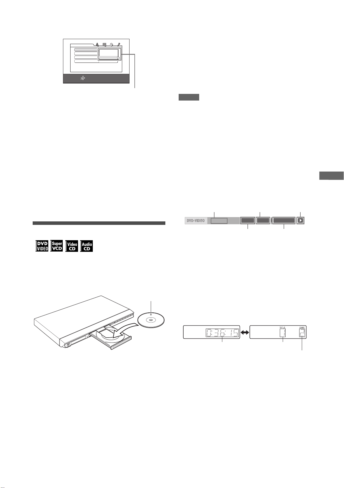
To check the playback status
You can see the current selection number (the title/chapter
number for DVD VIDEO or track number for SVCD/Video CD/
Audio CD), time information (the track or chapter time while
stopped, or elapsed track or chapter time during playback) and
the transport status (stop, playback, pause, etc.) on the TV
screen.
Press ON SCREEN.
Example: for DVD VIDEO
Transfer rate
8.5Mbps
Current chapter
number
TITLE 33 TOTAL 1:25:58CHAP 33
Current title number
Current transport
status
Disc elapsed
time
Note that pressing ON SCREEN again brings up the menu bar
under the status bar, from which you can access various
1
Press 0 (or OPEN/CLOSE on the remote
control unit) to open the disc tray.
2
Place a disc in the disc tray.
functions. See page 18 for details about the menu bar.
To turn off the status bar
Press ON SCREEN repeatedly until the status bar goes off.
To change the display window contents
With the label side up
• To insert an 8-cm disc, place it in the inner recess.
3
Press 0 (or OPEN/CLOSE on the remote
control unit) to close the disc tray.
4
Press 3 on the player or 3 (SELECT) on the
remote control unit.
The player starts playback from the beginning.
• Depending on the disc, playback starts when you close the
disc tray.
Press DISPLAY.
Example: for DVD VIDEO
Each time you press DISPLAY, the elapsed time display and
the title/chapter number display appear alternately.
Elapsed time
Title number
Chapter number
To stop playback completely
Press 7.
Hint
If you press 0 during playback, the player stops playback and
opens the disc tray.
To stop playback temporarily
Press 8.
To resume playback, press 3 (SELECT).
9
B
a
s
i
c
p
l
a
y
b
a
c
k
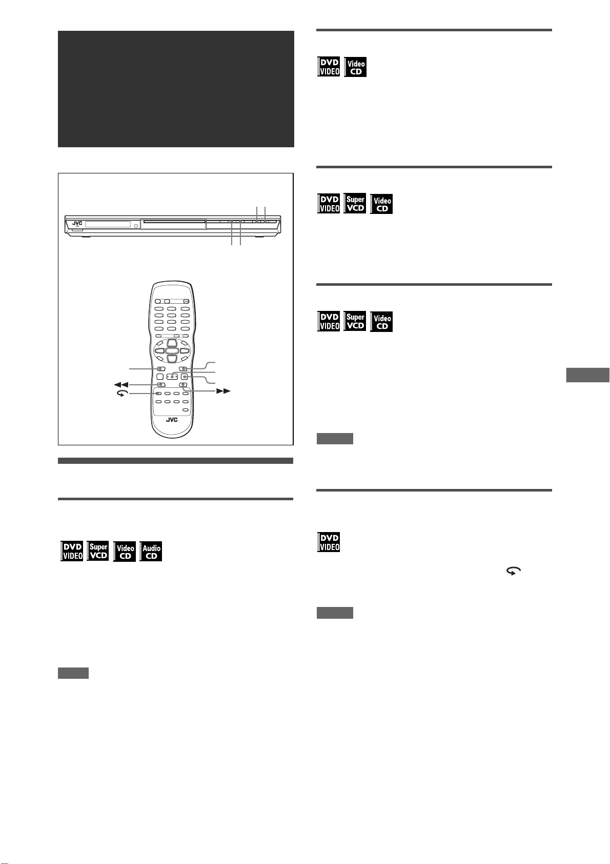
73
7
3 (SELECT)
Restarting playback after stopping
(resuming playback)
Changing the resume mode
The player has three resume modes; ON, OFF and DISC
RESUME.
• You can select the mode using the preference display (see
page 26).
When the resume mode is “OFF”
Playback always starts from the beginning.
When the resume mode is “DISC RESUME”
The player memorizes interrupted positions for the last 30 discs
played. Storing a new interrupted position will erase the
interrupted position stored for the first disc.
The memory of the interrupted positions are not cleared even if
you open the disc tray or turn off the player.
NOTES
• If you change the [RESUME] setting from [DISC RESUME] to
[OFF] or [ON], you cannot resume playback of a disc whose
“resuming” position is stored. However, when you again set
[RESUME] to [DISC RESUME], you will then be able to resume
playback of the disc.
• If you interrupt the playback of a disc for which an interrupted
position has already been stored, the memory will be updated
with the new interrupted position.
• For a double-sided DVD VIDEO disc, the player regards each
side as a different disc. Therefore, to resume playback of such a
disc, the disc must be inserted with the same side down.
• When the player memorizes an interrupted point for a disc, it
also memorizes Audio, Subtitle and Angle settings.
• The player may not resume playback exactly from the
interrupted point. In the case of an SVCD/Video CD disc with
PBC function, the player may resume playback from a point
slightly earlier or later than the point where playback was
interrupted.
The player resumes playback from the position you interrupted
playback, as long as the disc you interrupted playback is still on
the disc tray.
This is because the player’s resume mode is set to ON when you
purchased the player.
When the resume mode is set to ON, the player memorizes the
position on a disc where you interrupted playback.
• When you press 7 to interrupt playback, the TV screen shows
[RESUME STOP] and the [RESUME] indicator lights up in the
display window.
• When you re-start playback, the TV screen shows [RESUME
PLAY].
Hint
The memory of the interrupted position is not cleared even if you
turn off the player.
To play back from the beginning
Press 7 while the disc is stopped.
The memory is cleared.
Then press 3 (SELECT).
NOTES
• The player remembers the interrupted position even if you turn
the power off.
• The memory is cleared if you open the disc tray.
About On-screen guide icons
You may see the following icons displayed over the picture.
They have the following meanings.
: Appears at the beginning of playback mode.
: Appears at the beginning of pause mode.
: Appears at the beginning of fast forward/backward
playback with the current speed (see page 11).
: Appears at the beginning of slow-motion playback
with the current speed (see page 11).
: Appears at the beginning of a scene recorded from
multiple angles (see page 16).
: Appears at the beginning of a scene recorded with
multiple audio languages (see page 16).
: Appears at the beginning of a scene recorded with
multiple subtitle languages (see page 15).
You can change the setting so that the on-screen guide icons
do not appear on the TV screen (see page 26).
About screen saver function
A television monitor may have an image burned into it if a static
image is displayed for a long time. To prevent this, the player
automatically activates the screen saver function if a static
picture, such as an on-screen display or menu, is displayed
while no button is pressed for over 5 minutes.
When the screen saver function is activated, the TV screen
gets darker.
Pressing any buttons will release the screen saver function.
You can set the screen saver function to ON or OFF (see page
26).
10
V
a
r
i
o
u
s
k
i
n
d
s
o
f
p
l
a
y
b
a
c
k
Various kinds of
x1.5 Quick Playback with sound
playback
4
38
4¢
¢
3 (SELECT)
8
When you select 1.5 times normal speed playback, the disc is
played back with sound.
• For DVD VIDEO discs, the subtitle does not go off.
• At the x1.5 Quick Playback mode, the digital sound is output in
stereo linear PCM format.
• To switch from rapid reverse playback to x1.5 Quick Playback,
first press 3 (SELECT), then press ¡ once.
To advance a still picture frame by frame
While paused, press 8.
Each time you press 8, the still picture advances to the next
frame.
Pressing 3 (SELECT) returns to normal playback.
To play back in slow motion
You can select from 1/32 times, 1/16 times, 1/4 times and 1/2
times normal speed.
During playback, press 8, then press ¡ (to
play forward slow motion), or 1 (to play
reverse slow motion, for DVD VIDEO disc
only).
Pressing 3 (SELECT) returns to normal playback.
NOTES
• During slow motion playback, the sound will be muted.
• Reverse slow motion playback is not possible for an SVCD and
Playback at various speeds
Video CD.
To replay the previous scenes
To advance or reverse playback rapidly
(One touch replay function)
while monitoring
During playback, press ¡ or 1 on the
remote control unit.
You can select from 1.5 times, 5 times, 20 times and 60 times
normal speed. Pressing 3 (SELECT) returns the player to
normal playback.
During playback, hold down ¢ or 4.
Playback is advanced or reversed at 5 times normal speed.
NOTE
During rapid playback, the sound will be muted except when
playing an Audio CD, and when playing a DVD VIDEO or Video
CD at 1.5 times normal speed. For Audio CD discs, the sound will
be heard intermittently.
During DVD VIDEO playback, press .
The playback position moves back 10 seconds before the
current position.
NOTES
• This function works only within the same title, though it works
between chapters.
• This function may not work with some DVD VIDEO discs.
11
V
a
r
i
o
u
s
k
i
n
d
s
o
f
p
l
a
y
b
a
c
k
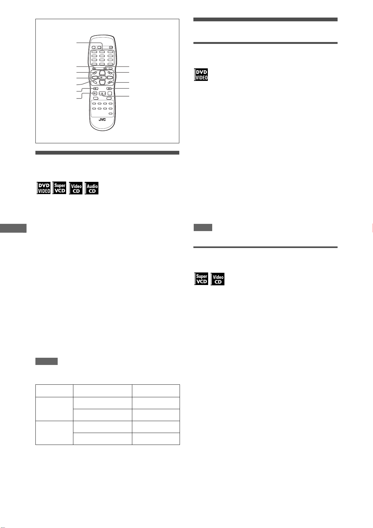
Numeric buttons
TITLE/GROUPRETURN
TOP MENU
5/∞/2/3
ENTER
4
7
MENU
ON SCREEN
¢
3 (SELECT)
Locating the beginning of a scene or
song
For DVD VIDEO: During playback, you can skip a chapter or title,
depending on the disc configuration.
For SVCD/Video CD: During playback without PBC function, you
can skip a track.
For Audio CD: During playback or while in stop mode, you can
skip a track.
To skip forward, press ¢.
Playing from a specific position
To locate a desired scene from the DVD
menu
DVD VIDEO discs generally have their own menus which show
the disc contents. These menus contain various items such as
titles of movies, names of songs, or artist information, and display
them on the TV screen. You can locate a desired scene using the
DVD m e n u.
1
While a DVD VIDEO disc is inserted, press
TOP MENU or MENU.
The menu appears on the TV screen.
2
Press 5/∞/2/3 to select a desired item, then
press ENTER or 3 (SELECT).
The player starts playback of the selected item.
Hints
• Some DVD VIDEO discs may also have a different menu which
appears when MENU is pressed.
• See the instructions of each DVD VIDEO disc for its particular
menu.
• With some discs, you can select items by entering the
corresponding number using the numeric buttons, which may
cause the player to automatically start playback.
NOTE
The MENU button does not work while stopped.
To skip backward, press 4 twice.
Using the numeric buttons
For DVD VIDEO/Audio CD: During playback or while in stop
mode
For SVCD/Video CD: During playback without PBC function or
while in stop mode
Press the numeric buttons to specify the
number.
To select 5: press 5.
To select 23: press +10, +10, then 3.
To select 40: press +10, +10, +10, then 10.
The player starts playback from the beginning of the
selection.
NOTES
• Depending on the disc type and the unit status, what is
specified differs:
Player status Disc type What is specified
While stopped DVD VIDEO title
SVCD/Video CD/Audio CD track
During playback DVD VIDEO chapter
• During DVD VIDEO playback, if a menu is shown on the TV
screen, the numeric buttons may be used for selecting an item
in the menu.
SVCD/Video CD/Audio CD track
To locate a desired scene from the menu of
a SVCD/Video CD with PBC
Some SVCD/Video CD discs support the PBC function. PBC is
an abbreviation of “Playback Control.” Some SVCD/Video CD
discs recorded with PBC have their own menus, such as a list of
the songs of the disc. You can locate a specific scene by using
the PBC menu.
1
In stop mode, press 3 (SELECT) or TOP
MENU.
A disc menu appears on the TV screen.
2
Press the numeric buttons to select the
desired item.
To select 5: press 5.
To select 23: press +10, +10, then 3.
To select 40: press +10, +10, +10, then 10.
The player starts playback of the selected item.
To return to the menu, press RETURN.
Hint
If something like [NEXT] or [PREVIOUS] appears on the TV
screen, pressing ¢ advances to the next page, and pressing
4 returns to the previous page.
12
 Loading...