

Page 1
SERVICE MANUAL
DVD PLAYER
YD03420048
XV-N318S
Area Suffix
US ---------------- Singapore
Turkey,South Africa,Egypt
UG UX ------------- Saudi Arabia
UF ---------------------- China
UB --------------- Hong Kong
KARAOKE
DVD
STANDBY/ON
OPEN
/CLOSE
DISPLAY
213
546
879
010 +10
RESERVE
TITLE/GROUP
CANCELRETURN
U
M
N
E
E
N
M
U
P
THUMBNAIL
O
T
S
E
T
SLOW
KARAOKE
ANGLE
SLIDE EFFECT
/LIST
ENTER
N
E
E
R
U
C
P
S
N
O
NEXTPREVIOUS
SELECTCLEAR
-
SLOW+
SOUND
VFPREPEAT
EFFECT
PROGRESSIVE
KARAOKE
VOCAL
SCAN
SOUND
SUB TITLE
ZOOM
AUDIO
ECHO
KEY+
DIMMER
KEY
VIDEO
XV-N318SUS2C, XV-N318SUG2C, XV-N318SUX2C, XV-N318SUF2C, XV-N318SUB2C
TABLE OF CONTENTS
1 PRECAUTION. . . . . . . . . . . . . . . . . . . . . . . . . . . . . . . . . . . . . . . . . . . . . . . . . . . . . . . . . . . . . . . . . . . . . . . . . 1-3
2 SPECIFIC SERVICE INSTRUCTIONS . . . . . . . . . . . . . . . . . . . . . . . . . . . . . . . . . . . . . . . . . . . . . . . . . . . . . . 1-7
3 DISASSEMBLY . . . . . . . . . . . . . . . . . . . . . . . . . . . . . . . . . . . . . . . . . . . . . . . . . . . . . . . . . . . . . . . . . . . . . . . 1-8
4 ADJUSTMENT . . . . . . . . . . . . . . . . . . . . . . . . . . . . . . . . . . . . . . . . . . . . . . . . . . . . . . . . . . . . . . . . . . . . . . . 1-14
5 TROUBLESHOOTING . . . . . . . . . . . . . . . . . . . . . . . . . . . . . . . . . . . . . . . . . . . . . . . . . . . . . . . . . . . . . . . . . 1-17
COPYRIGHT © 2004 Victor Company of Japan, Limited
No.YD034
2004/8
Page 2
SPECIFICATION
Specifications and appearance are subject to change without prior notice.
XV-N318S for US,UG,UX,UF,UB
General
Readable discs DVD VIDEO, DVD-R (Video format), DVD-RW (Video format), SVCD, Video CD, Audio CD (CD-DA), CD-R/
RW (CD-DA, SVCD, Video CD, MP3 format, JPEG, MPEG-4)
Video format PAL, 625i (Interlaced scan)NTSC, 525i (Interlaced scan)/525p (Progressive scan) selectable
Other
Power requirements AC 110 V - 240 V~ , 50 Hz/60 Hz
Power consumption 11.0 W (POWER ON), 2.0 W (STANDBY mode)
Mass 1.6 k g
Dimensions (W × H × D) 435 mm × 44 mm × 201 mm
Video outputs
COMPONENT (pin jacks) Y Output: 1.0 Vp-p (75 Ω)
Pb/Pr Output: 0.7 Vp-p(75 Ω)
VIDEO OUT (pin jack) 1.0 Vp-p (75 Ω)
S-VIDEO OUT (S jack) Y Output: 1.0 Vp-p (75 Ω)
C Output: 286 mVp-p (75 Ω)
Horizontal resolution 500 lines or more
Audio input
MIC 1/2 4mVrms (8.2 kΩ)
Audio outputs
ANALOG OUT (pin jack) 2.0 Vrms (10 kΩ)
DIGITAL OUT (COAXIAL) 0.5 Vp-p (75 Ω termination)
Audio characteristics
Frequency response CD (sampling frequency 44.1 kHz):2 Hz to 20 kHz
DVD (sampling frequency 48 kHz):2 Hz to 22 kHz
(4 Hz to 20 kHz for DTS and Dolby Digital bitstream signals)
DVD (sampling frequency 96 kHz)2 Hz to 44 kHz
Dynamic range 16 bit: More than 98 dB
20 bit/24 bit: More than 100 dB
Wow and flutter Unmeasurable (less than +- 0.002%)
Total harmonic distortion less than 0.009%
• Manufactured under license from Dolby Laboratories. "Dolby" and the double-D symbol are trademarkes of Dolby Laboratories.
• "DTS" and "DTS 2.0+Digital Out" are trademarks of Digital Theater Systems, Inc.
• USE OF THIS PRODUCT IN ANY MANNER THAT COMPLIES WITH THE MPEG-4 VISUAL STANDARD IS PROHIBITED, EXCEPT FOR
USE BY A CONSUMER ENGAGING IN PERSONAL AND NON-COMMERCIAL ACTIVITIES.
• This product incorporates copyright protection technology that is protected by U.S. patents and other intellectual property rights. Use of this
copyright protection technology must be authorized by Macrovision, and is intended for home and other limited viewing uses only unless
otherwise authorized by Macrovision. Reverse engineering or disassembly is prohibited.
• “CONSUMERS SHOULD NOTE THAT NOT ALL HIGH DEFINITION TELEVISION SETS ARE FULLY COMPATIBLE WITH THIS PRODUCT AND MAY CAUSE ARTIFACTS TO BE DISPLAYED IN THE PICTURE. IN CASE OF 525 OR 625 PROGRESSIVE SCAN PICTURE
PROBLEMS, IT IS RECOMMENDED THAT THE USER SWITCH THE CONNECTION TO THE “STANDARD DEFINITION” OUTPUT. IF
THERE ARE QUESTIONS REGARDING OUR TV SET COMPATIBILITY WITH THIS MODEL 525p AND 625p DVD PLAYER, PLEASE
CONTACT OUR CUSTOMER SERVICE CENTER.”
Digital output signal chart
Disc type
DVD with 48/44.1 kHz, 16/20/24
bit linear PCM
DVD with DTS 48 kHz, 16 bit, stereo linear PCM DTS bitstream
DVD with Dolby Digital 48 kHz, 16 bit, stereo linear PCM Dolby Digital bitstream
DVD with MPEG Multichannel 48 kHz, 16 bit, stereo linear PCM MPEG bitstream
SVCD/Video CD/Audio CD 44.1 kHz, 16 bit, stereo linear PCM
Audio CD with DTS 48 kHz, 16 bit, stereo linear PCM DTS bitstream
CD-R/RW with MP3 Linear PCM
CD-R/RW with MPEG-4 No output
PCM ONLY DOLBY DIGITAL/PCM STREAM/PCM
48/44.1 kHz, 16 bit, stereo linear PCM
Output
1-2 (No.YD034)
Page 3
SECTION 1
PRECAUTION
1.1 Safety Precautions
(1) This design of this product contains special hardware and
many circuits and components specially for safety purposes. For continued protection, no changes should be made
to the original design unless authorized in writing by the
manufacturer. Replacement parts must be identical to
those used in the original circuits. Services should be performed by qualified personnel only.
(2) Alterations of the design or circuitry of the product should
not be made. Any design alterations of the product should
not be made. Any design alterations or additions will void
the manufacturers warranty and will further relieve the
manufacture of responsibility for personal injury or property
damage resulting therefrom.
(3) Many electrical and mechanical parts in the products have
special safety-related characteristics. These characteristics are often not evident from visual inspection nor can the
protection afforded by them necessarily be obtained by using replacement components rated for higher voltage, wattage, etc. Replacement parts which have these special
safety characteristics are identified in the Parts List of Service Manual. Electrical components having such features
are identified by shading on the schematics and by ( ) on
the Parts List in the Service Manual. The use of a substitute
replacement which does not have the same safety characteristics as the recommended replacement parts shown in
the Parts List of Service Manual may create shock, fire, or
other hazards.
(4) The leads in the products are routed and dressed with ties,
clamps, tubings, barriers and the like to be separated from
live parts, high temperature parts, moving parts and/or
sharp edges for the prevention of electric shock and fire
hazard. When service is required, the original lead routing
and dress should be observed, and it should be confirmed
that they have been returned to normal, after reassembling.
(5) Leakage shock hazard testing)
After reassembling the product, always perform an isolation check on the exposed metal parts of the product (antenna terminals, knobs, metal cabinet, screw heads,
headphone jack, control shafts, etc.) to be sure the product
is safe to operate without danger of electrical shock.Do not
use a line isolation transformer during this check.
• Plug the AC line cord directly into the AC outlet. Using a
"Leakage Current Tester", measure the leakage current
from each exposed metal parts of the cabinet, particularly any exposed metal part having a return path to the
chassis, to a known good earth ground. Any leakage current must not exceed 0.5mA AC (r.m.s.).
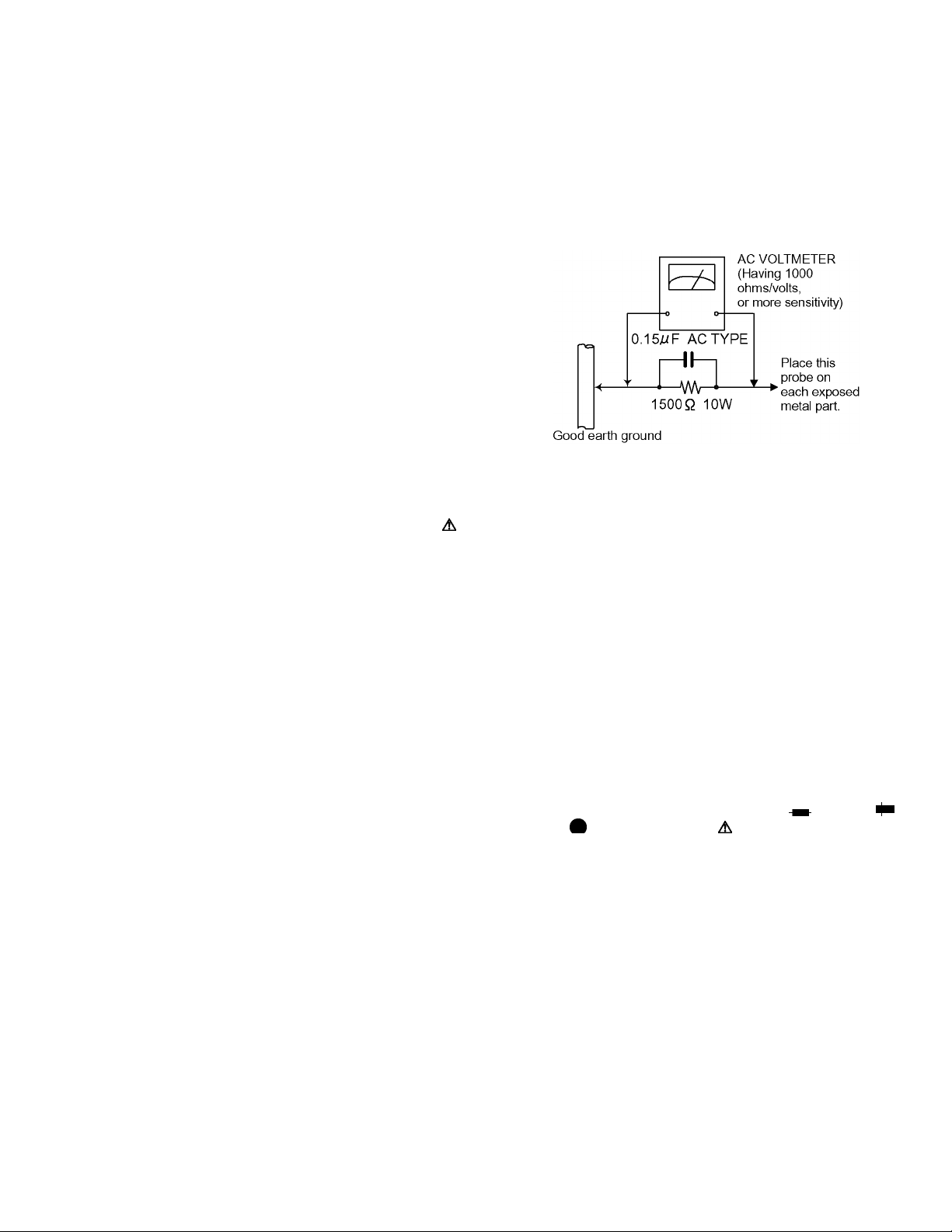
• Alternate check method
Plug the AC line cord directly into the AC outlet. Use an
AC voltmeter having, 1,000 ohms per volt or more sensitivity in the following manner. Connect a 1,500 ohm 10W
resistor paralleled by a 0.15 F AC-type capacitor between an exposed metal part and a known good earth
ground.
Measure the AC voltage across the resistor with the AC
voltmeter.
Move the resistor connection to each exposed metal
part, particularly any exposed metal part having a return
path to the chassis, and measure the AC voltage across
the resistor. Now, reverse the plug in the AC outlet and
repeat each measurement. Voltage measured any must
not exceed 0.75 V AC (r.m.s.). This corresponds to 0.5
mA AC (r.m.s.).
1.2 Warning
(1) This equipment has been designed and manufactured to
meet international safety standards.
(2) It is the legal responsibility of the repairer to ensure that
these safety standards are maintained.
(3) Repairs must be made in accordance with the relevant
safety standards.
(4) It is essential that safety critical components are replaced
by approved parts.
(5) If mains voltage selector is provided, check setting for local
voltage.
1.3 Caution
Burrs formed during molding may be left over on some parts
of the chassis.
Therefore, pay attention to such burrs in the case of preforming repair of this system.
1.4 Critical parts for safety
In regard with component parts appearing on the silk-screen
printed side (parts side) of the PWB diagrams, the parts that are
printed over with black such as the resistor ( ), diode ( )
and ICP ( ) or identified by the " " mark nearby are critical for
safety. When replacing them, be sure to use the parts of the
same type and rating as specified by the manufacturer. (Except
the JC version)
(No.YD034)1-3
Page 4
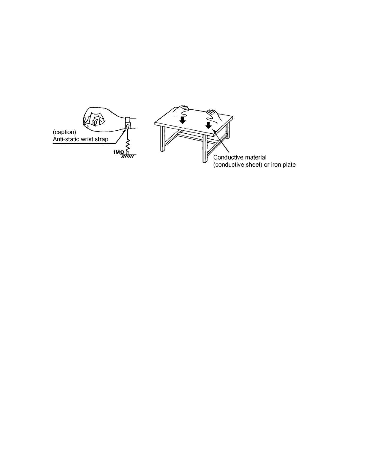
1.5 Preventing static electricity
Electrostatic discharge (ESD), which occurs when static electricity stored in the body, fabric, etc. is discharged, can destroy the laser
diode in the traverse unit (optical pickup). Take care to prevent this when performing repairs.
1.5.1 Grounding to prevent damage by static electricity
Static electricity in the work area can destroy the optical pickup (laser diode) in devices such as DVD players.
Be careful to use proper grounding in the area where repairs are being performed.
(1) Ground the workbench
Ground the workbench by laying conductive material (such as a conductive sheet) or an iron plate over it before placing the
traverse unit (optical pickup) on it.
(2) Ground yourself
Use an anti-static wrist strap to release any static electricity built up in your body.
(3) Handling the optical pickup
• In order to maintain quality during transport and before installation, both sides of the laser diode on the replacement optical
pickup are shorted. After replacement, return the shorted parts to their original condition.
(Refer to the text.)
• Do not use a tester to check the condition of the laser diode in the optical pickup. The tester's internal power source can easily
destroy the laser diode.
1.6 Handling the traverse unit (optical pickup)
(1) Do not subject the traverse unit (optical pickup) to strong shocks, as it is a sensitive, complex unit.
(2) Cut off the shorted part of the flexible cable using nippers, etc. after replacing the optical pickup. For specific details, refer to the
replacement procedure in the text. Remove the anti-static pin when replacing the traverse unit. Be careful not to take too long
a time when attaching it to the connector.
(3) Handle the flexible cable carefully as it may break when subjected to strong force.
(4) I t is not possible to adjust the semi-fixed resistor that adjusts the laser power. Do not turn it.
1.7 Precautions of the safe use of battery
• Store the battery in a place where children cannot reach.If a child accidentally swallows the battery, consult a doctorimmediately.
• Do not recharge, short, disassemble or heat the battery or dispose of it in a fire.
Doing any of these things may cause the battery to give off heat, crack, or start a fire.
• Do not leave the battery with other metallic materials.Doing this may cause the battery to give off heat, crack, or start a fire.
• When throwing away or saving the battery, wrap it in tape and insulate; otherwise, the battery may start to give off heat, crack, or
start a fire.
• Do not poke the battery with tweezers or similar tools.Doing this may cause the battery to give off heat, crack, or start a fire.
• Dispose of batteries in the proper manner, according to federal, state, and local regulations.
1-4 (No.YD034)
Page 5
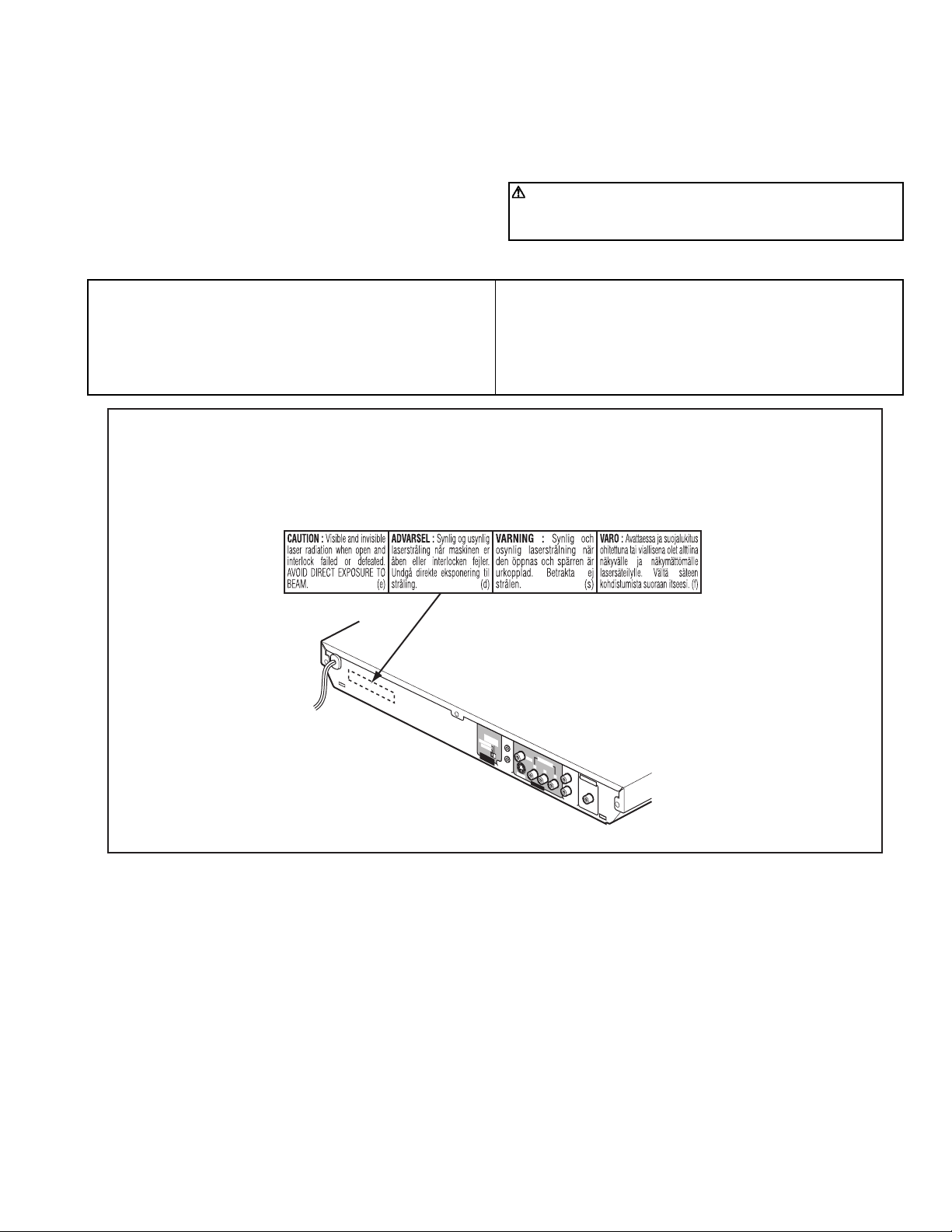
1.8 Important for laser products
(1) CLASS 1 LASER PRODUCT
(2) DANGER : Invisible laser radiation when open and inter
lock failed or defeated. Avoid direct exposure to beam.
(3) CAUTION : There are no serviceable parts inside the
Laser Unit. Do not disassemble the Laser Unit. Replace the
complete Laser Unit if it malfunctions.
(4) CAUTION : The compact disc player uses invisible laser
radiation and is equipped with safety switches which
prevent emission of radiation when the drawer is open and
the safety interlocks have failed or are de feated.
It is dangerous to defeat the safety switches.
VARNING
Osynlig laserstrålning är denna del är öppnad och spårren är
urkopplad. Betrakta ej strålen.
VARO
Avattaessa ja suojalukitus ohitettaessa olet alttiina näkymättömälle lasersäteilylle. Älä katso säteeseen.
ADVARSEL
Usynlig laserstråling ved åbning, når sikkerhedsafbrydere er
ude af funktion. Undgå udsasttelse for stråling.
ADVARSEL
Usynlig laserstråling ved åpning, når sikkerhetsbryteren er avslott. unngå utsettelse for stråling.
REPRODUCTION AND POSITION OF LABEL and PRINT
WARNING LABEL and PRINT
(5) CAUTION : If safety switches malfunction, the laser is able
to function.
(6) CAUTION : Use of controls, adjustments or performance of
procedures other than those specified herein may result in
hazardous radiation exposure.
CAUTION
Please use enough caution not to see the beam directly
or touch it in case of anadjustment or operation check.
The inside of a rear panel
N
T
S
C
5
25
i
NT
/
p
R
SC
E
M
O
525i
T
E
P
A
L 625i
VI
DEO
SIGN
V
SELE
ID
CO
E
O
A
L
C
T
OR
MP
ONE
N
A
C
O
M
P
U
T
V
Y
L
I
N
P
K
B
S
-
V
I
DE
P
O
R
D
IGIT
L
E
F
T
P
VIDEO
CM/STR
O
UT
R
IG
H
T
A
UDI
O
O
U
T
AL O
U
T
EAM
C
O
A
X
I
A
L
(No.YD034)1-5
Page 6
1.9 Precautions for Service
1.9.1 Handling of Traverse Unit and Laser Pickup
(1) Do not touch any peripheral element of the pickup or the actuator.
(2) The traverse unit and the pickup are precision devices and therefore must not be subjected to strong shock.
(3) Do not use a tester to examine the laser diode. (The diode can easily be destroyed by the internal power supply of the tester.)
(4) To replace the traverse unit, pull out the metal short pin for protection from charging.
(5) When replacing the pickup, after mounting a new pickup, remove the solder on the short land which is provided at the center of
the flexible wire to open the circuit.
(6) Half-fixed resistors for laser power adjustment are adjusted in pairs at shipment to match the characteristics of the optical block.
Do not change the setting of these half-fixed resistors for laser power adjustment.
1.9.2 Destruction of Traverse Unit and Laser Pickup by Static Electricity
Laser diodes are easily destroyed by static electricity charged on clothingor the human body. Before repairing peripheral elements of
the traverse unit or pickup, be sure to take the following electrostatic protection:
(1) Wear an antistatic wrist wrap.
(2) With a conductive sheet or a steel plate on the workbench on which the traverse unit or the pick up is to be repaired, ground the
sheet or the plate.
(3) It solders to two short circuit sections on the substrate of a pick-up.
(4) After removing the flexible wire from the connector (CN101
), short-circuit the flexible wire by the metal clip.
(5) Short-circuit the laser diode by soldering the land which is provided at the center of the flexible wire for the pickup.
After completing the repair, remove the solder to open the circuit.
Gear1
Pick-up
Short circuit
*Please refer to the disassembly method for details.
CN101
Main board
1-6 (No.YD034)
Page 7

SECTION 2
SPECIFIC SERVICE INSTRUCTIONS
This service manual does not describe SPECIFIC SERVICE INSTRUCTIONS.
(No.YD034)1-7
Page 8

SECTION 3
TOP COVER
Push
y
DISASSEMBLY
3.1 Main body section
3.1.1 Removing the top cover (See Figure 1)
(1) Remove the two screws A attaching the top cover on both
sides of the main body.
(2) Remove the three screws B attaching the top cover on the
back of the main body.
(3) Raise the both sides and lower part of the rear of the top
cover, with opening them slightly in an outward direction.
And the top cover will be removed.
3.1.2 Removing the mechanism assembly (See Figure 2, Figure 3, Figure 4)
• Prior to performing the following procedure, remove the top
cover.
• There is no need to remove the front panel assembly.
(1) Insert a kind of screwdriver in a hole located in the right
side of mechanism assembly, and push a lever until it cannot be inserted any further.
(2) And then, a tray will come out. Remove the tray in an upper
direction, with slightly opening the lower part of fitting in an
outward direction.
(3) Remove the three screws C attaching the mechanism as-
sembly.
(4) A tray is made to slide ahead.
(5) A gear 1 is turned counterclockwise. Then, a pick-up unit
moves back.
(6) It solders to two a sections on the pick-up unit.
(7) Disconnect the card wire from connector CN201
CN101 on the main board.
ATTENTION:
Please extract the wire after short-circuited of two places
on the wire in part a with solder. Please remove the solder two places of part a after connecting the wire with
when reassembling.
CN101
CAUTION:
Be sure to solder the short land sections “a” on the pickup unit before disconnecting the card wire from connector CN101
If the card wire is disconnected without attaching solder,
the pick-up unit may be destroyed by static electricity.
(8) Remove the mechanism assembly by lifting the rear part of
the mechanism assembly.
on the main board.
, CN202,
A x 2
Mechanism assembl
Fitting
TOP COVER
TOP COVER
B
Fig.1
Front panel assembly
Tr ay
Push
Fig.2
C
Fig.3
B
B
Mechanism assembly
Hole and lever
C
C
CN201
CN101CN202
Main board
1-8 (No.YD034)
Section a
Gear1
Pick-up
Fig.4
Page 9

3.1.3 Removing the front panel assembly (See Figure 5, Figure 6 )
• Prior to performing the following procedure, remove the top
cover/mechanism assembly
(1) Disconnect the card wire from connector CN502
main board.
(2) Disconnect the flat wire from connector CN702
board.
(3) Remove the one screw D attaching the MIC bracket.
(4) Hook b and c are removed respectively, and the front panel
assembly is removed.
on the
on the main
D
Front panel assembly
CN502
3.1.4 Removing the rear panel (See Figure 7 )
• Prior to performing the following procedure, remove the top
cover.
(1) Remove the seven screws E attaching the rear panel.
(2) Disconnect the power cord from connector P901
power board
on the
Front panel
assembly
Hook c
Hook b
Power board
Fig.5
Hook c
Fig.6
Main board
Hook c
CN702
Hook b
3.1.5 Removing the main board and power board. (See Figure 8)
• Prior to performing the following procedure, remove the top
cover/rear panel.
(1) Remove the two screws F attaching the main board.
(2) Disconnect the card wire from connector CN201
CN202,CN502, CN101 on the main board.
(3) Disconnect the flat wire from connector CN702
board.
(4) Disconnect the flat wire from connector CN901
er board.
(5) Remove the three screws G attaching the power board.
on the main
on the pow-
,
P901 Rear panel E
E
Fig.7
Power board
G
CN901
G
G
F
Fig.8
CN502CN202
CN201
CN101
F
CN702
Main board
(No.YD034)1-9
Page 10

3.2 Loading mechanism assembly
Projection of the tray
3.2.1 Removing the tray (See Figure 1, Figure 2, Figure 3, Figure 4, Figure 5, Figure 6)
(1) Push a of the slide cam on the hole in the right side of the
loading base by using a driver until it stops. (See Figure 1.)
(2) The tray comes out. Pull the tray in a front direction until it
stops.
(3) Remove the two screws A attaching the leaf spring. (See
Figure 2.)
(4) Tilt the tray in a direction of the arrow around the point in
the left rear part of the tray. (See Figure 3.)
(5) The rail of the tray is removed from b of the loading base.
Then, remove the tray upward. (See Figure 4.)
Attaching the tray:
Engage c of the loading base to the projection of the tray while
tilting the tray to the left. Turn the tray in a direction of the arrow, and attach the leaf spring. (See Figure 5.)
Note:
Prior to the procedure above, move the slide cam in a direction
of the arrow so that d of the slide cam can be inserted in e of
the tray. (See Figure 6.)
Tray
The point in the left rear part
Tray
Fig.3
Push
Slide cam part a
Leaf spring
A
Fig.1
Fig.2
A
Loading base
Tray
Loading base part b
Rail of the tray
Fig.4
Projection of the tray
Loading base part c
Fig.5
Par t e
1-10 (No.YD034)
Par t d
Slide cam
Fig.6
Page 11

3.2.2 Removing the traverse mechanism assembly (See Figure 7)
Shaft
(1) Reverse the loading mechanism assembly.
(2) A card wire is removed from a FFC holder.
(3) Remove the four screws B attaching the traverse mecha-
nism assembly. Remove the traverse mechanism assembly upward.
FFC Holder
Loading mechanism
B
assembly
B
3.2.3 Removing the elevator (See Figure 8 and Figure 9)
• Prior to the following procedure, remove the traverse mechanism assembly.
(1) Remove the two arms of the elevator from the two parts f
by moving the arms in a direction of the arrow.
(2) Pull out the elevator in a rear direction.
Attaching the elevator:
Engage the two holes g to the two shafts on the front part of
the elevator. And then, attach the elevator.
Par t f
Elevator
Traverse mechanism
B
Fig.7
Fig.8
assembly
g
Elevator
Slide cam
B
Par t f
g
Shaft
Fig.9
(No.YD034)1-11
Page 12

3.2.4 Removing the loading motor (See Figure 10 and Figure 11)
• Prior to the following procedure, remove the tray, the traverse
mechanism assembly, and the elevator.
(1) Remove the belt from the pulley gear.
(2) Remove two screws C attaching the loading motor.
(3) Remove two solders h on the switch board.
Pulley gear
Switch board
Part
Belt
㧯
Fig.10
Loading base
Motor Pulley
㧯
Slide cam
Loading motor
h
Fig.11
1-12 (No.YD034)
Page 13

3.3 Traverse mechanism assembly
3.3.1 Removing the pickup (See Figure 12, Figure 13)
• Prior to the following procedure, remove the traverse mechanism assembly.
(1) Remove one screw D attaching the plate.
(2) Remove the plate and the thurust spring.
(3) Lift i of the shaft 1, and pull out the shaft 1 from j.
(4) Remove k of the pickup from the shaft 2.
Attaching the pickup:
(1) Engage k of the pickup to the shaft 2.
(2) A spring is lifted and shaft 1 is inserted in the j, and at-
tach the shaft 1 to i.
(3) Attach the thurust spring, and then attach the plate. Fix
the thurust spring and the plate by using the screw D.
spring
D
Thurust spring
Plate
Fig.12
Part j
spring
Shaft 2
Part k
Shaft 1
Part i
Fig.13
(No.YD034)1-13
Page 14

SECTION 4
ADJUSTMENT
4.1 Test mode setting method
(1) Unplug the power plug.
(2) Insert power plug into outlet while pressing both "PLAY" key and "STOP" key of the main body.
(3) The FL display shows "N300J", and the main body turns to test mode.
*The portion of "N300J" changes with a model and destinations.
(4) To release test mode, press "POWER" key of the main body.
NOTE:
Each pressing of "SET UP" key of the remote controller in test mode changes the mode as follows.
Message area of TV screen
N300J ------------------
-------------
AT ----------------
----------------
Becomes test mode ----
Version of backend -----
Name of flash ROM
Version of frontend -----
TEST MODE
BE VERSION :
TEST MODE
FE VERSION :
Message area
FL Display becomes all lighting
CHCK -------------------
4.2 Initialization method
Please initialize according to the following procedures in the following case :
• Just after you upgrade the firmware
• After you confirm the symptoms that a customer points out. First initialize, and then confirm whether the symptoms are improved or
not.
• After servicing, before returning the main body to a customer. (Initialized main body should be returned to a customer.)
(1) Set the main body at test mode.
(2) Press "FWD SKIP" key of the main body.
(3) When indicate "P" on the FL display, initialization is completed.
KARAOKE
DVD
STANDBY/ON
OPEN
/CLOSE
DISPLAY
213
546
879
010 +10
RESERVE
TITLE/GROUP
CANCELRETURN
U
M
N
E
E
M
P
THUMBNAIL
O
T
/LIST
ENTER
S
E
T
U
C
P
S
N
O
NEXTPREVIOUS
SELECTCLEAR
-
SLOW+
SLOW
SOUND
VFPREPEAT
EFFECT
PROGRESSIVE
KARAOKE
VOCAL
KARAOKE
SCAN
SOUND
SUB TITLE
ANGLE
ZOOM
AUDIO
ECHO
SLIDE EFFECT
KEY+
DIMMER
KEY
Check mode --------------
N
U
SET UP key
(switch of mode)
N
E
E
R
POWER key
FL Display
CHECK MODE
PLAY key
(for test mode)
STOP key
(for test mode)
1-14 (No.YD034)
FWD SKIP key
(for initialize)
Page 15

4.3 Upgrading of firmware
The latest firmware for upgrading is updated in "Digital Video Storage" page in JS-NET. At the time of service,
compare the version of the product and the latest version, and upgrade the old version into the latest version.
4.3.1 Distribution method
(1) Compressed file is distributed through JS-NET.
(2) Download the version of the destination of the model, and self-extract the file.
(3) "bank XXX.rom" file is made.(The portion of “XXX” may change with firm wares.)
(4) Write "bank XXX.rom" file in the root of CD-R/RW. (Folders such as jvc_dvd are not necessary.)
4.3.2 Upgrade method
(1) Prepare upgrade disc with "bank XXX.rom" file written in its root.
(2) Press "POWER" key of the main body to turn the main body on.
(3) Insert the upgrade disc.
(4) The contents of disc are read automatically and upgrade is started.
(5) TV screen 1/29,2/29... if the count-up is displayed and it becomes 29/29, it will be displayed on FL display as "DONE", and up-
grade will be completed.
(6) When upgrade finishes, the main body changes from the POWER ON mode to STANDBY mode.
(7) Press the "OPEN/CLOSE" key, and open the tray to eject the disc.
(8) Set the main body at test mode, and perform initialization. Then, confirm the version of the firmware.
(No.YD034)1-15
Page 16

4.4 Confirm method of operation
Please confirm the operation of the undermentioned item after doing the repair and the upgrade of the firmware.
Initialize Refer to the initialization method.
Opening picture check (Power ON) It should be display "JVC"
Muting working The noise must not be had to the performance beginning when you push "PLAY" button or
at ON/STANDBY.
FL Display The mark and the logo, etc. displayed by each operation must be displayed correctly.
FL Display should light correctly without any unevenness.
All Function button All function buttons should worked correctly with moderate click feeling.
Open and close movement of tray When press OPEN/CLOSE button the tray should move smoothly without any noise.
Remote controller unit working Check the correctly operation in use of remote controller unit.
Reading of TOC Be not long in the malfunction.
Search Both forward-searches and backward-searches should be able to be done.Do not stop be
searching or after the search.
Skip Both forward-skip and backward-skip should be able to be done.Do not stop be after the skip.
Playback Do not find abnormality etc. of tone quality and the picture quality.
Most outside TITLE playback check Play VT-501 TITLE 59 CHAPTER 1 , check normal playback.
1-16 (No.YD034)
Page 17

5.1 Servo volume
Press OPEN
/CLOSE key
SECTION 5
TROUBLESHOOTING
Is tray
operation
Confirmation of tray drive circuit
N
and circuit in surrounding
correct?
Y
Is the traverse moving
along the innermost
N
perimeter for SW detection?
Y
"NO DISC" message appears
Y
immediately after vertical
movement of the pick-up lens
N
The state that DISC does not rotate continues for
several seconds, and becomes NO DISC or an
error display afterwards.
The rotation of DISC becomes high-speed and
abnormal, and becomes NO DISC or an error
display afterwards.
N
Is focus retraction OK?
FE
OFF
Even when it retracts
correctly, if it is out of focus
and makes repeated retries
with a clicking sound, it is
in error.
ON
See "(4) Focus ON error"
N
in "Check points for
individual errors"
Y
Is tracking retraction OK?
See "(3) Traverse movement error"
in "Check points for individual errors"
See "(2) Disk detection, distinction error"
in "Check points for individual errors"
Y
See "(1) Spindle startup error"
in "Check points for individual errors"
Is the inter-layer jump OK?
FE
LO LI
A
Two layers of DVD only.
N
(8) Inter-layer
jump error
Y
TE
OFF
If TE waveform reappears
or fails to converge after the
TE retraction, it is in error.
ON
Y
Is the spindle servo
locked correctly?
Is the RF OUT waveform
locked correctly?
Y
A
See "(5) Tracking ON error"
N
in "Check points for
individual errors"
See "(6) Spindle CLV error"
N
in "Check points for
individual errors"
Fig.1
Has the disc information
been collected?
Stop will result
Y
Is playback
N
possible?
Y
OK !
N
(7) Address read
error
Check (9),(10),(11), and
(12) items in "Check points
for individual errors"
(No.YD034)1-17
Page 18

5.2 Check points for each error
5.2.1 Spindle start error
(1) Defective spindle motor
• Are there several ohms resistance between each pin of CN201
(The power supply is turned off and measured.)
• Is the sign wave of about 100mVp-p in the voltage had from each terminal?
[ CN201"10"(H1+),"11"(H1-),"7"(H2+),"8"(H2-),"5"(H3+),"6"(H3-) ]
(2) Defective spindle motor driver (IC251
• Has motor drive voltage of a sign wave or a rectangular wave gone out to each terminal(SM1~3)
of CN201"1,2,3" and IC251"2,4,7"?
• Is FG pulse output from the terminal of IC251
• Is it "L(about 0.9V)" while terminal of IC251
(3) Has the control signal come from servo IC or the microcomputer?
• Is it "H" while the terminal of IC251"23"(/SPMUTE) is operating?
• Is the control signal input to the terminal of IC251
(changes from VHALF voltage while the motor is working.)
• Is the VHALF voltage input to the terminal of IC251
(4) Is the FG signal input to the servo IC?
• Is FG pulse input to the terminal of IC301
5.2.2 Disc Detection, Distinction error (no disc, no RFENV)
• Laser is defective.
• Front End Processor is defective (IC101
• APC circuit is defective. --- Q101
• Pattern is defective. --- Lines for CN101 - All patterns which relate to pick-up and patterns between IC101
• IC101 --- For signal from IC101 to IC301, is signal output from IC101 "57"(RFO) and IC101 "40" (FE)?
)
"24"(FG) according to the rotation of the motor?
"15"(VH) is rotating the motor?
"22"(EC)?
"21"(ECR)?
"177"(FG) according to the rotation of the motor?
).
, Q102.
"1-2","2-3","1-3"?
5.2.3 Traverse movement NG
(1) Defective traverse driver
• Has the voltage come between terminal of CN101 "2" and "4" ?
(2) Defective BTL driver (IC201
• Has the motor drive voltage gone out to IC201"17" or "18"?
(3) Has the control signal come from servo IC or the microcomputer?
• Is it "H" while the terminal of IC201
• TRSDRV Is the signal input? (IC301
(4) TRVSW is the signal input from microcomputer? (IC301
5.2.4 Focus ON NG
• Is FE output ? --- Pattern, IC101
• Is FODRV signal sent ? (R209) --- Pattern, IC301 "172"
• Is driving voltage sent ?IC201
• Mechanical unit is defective.
5.2.5 Tracking ON NG
• When the tracking loop cannot be drawn in, TE shape of waves does not settle.
• Mechanical unit is defective.
Because the self adjustment cannot be normally adjusted, the thing which cannot be normally drawn in is thought.
• Periphery of driver (IC201
Constant or IC it self is defective.
• Servo IC (IC301
When improperly adjusted due to defective IC.
)
)
"9"(STBY1) ?
"174")
"188")
"13", "14" --- If NG, pattern, driver, mechanical unit .
)
1-18 (No.YD034)
Page 19

5.2.6 Spindle CLV NG
• IC101 -- "55"(DIN), "54(DIP).
• Does not the input or the output of driver's spindle signal do the grip?
• Has the tracking been turned on?
• Spindle motor and driver is defective.
• Additionally, "IC101
5.2.7 Address read NG
• Besides, the undermentioned cause is thought though specific of the cause is difficult because various factors are thought.
Mechanism is defective. (jitter)
IC301
The disc is dirty or the wound has adhered.
5.2.8 Between layers jump NG (double-layer disc only)
Mechanism defective
Defect of driver's IC(IC201
Defect of servo control IC(IC301)
5.2.9 Neither picture nor sound is output
(1) It is not possible search
• Has the tracking been turned on?
• To "(5) Tracking ON NG" in "Check points for each error" when the tracking is not normal.
• Is the feed operation normal?
To "(3) traverse movement NG" in "Check points for each error" when it is not normal.Are not there caught of the feeding mechanism etc?
and IC301" and "Mechanism is defective(jitter)", etc. are thought.
)
5.2.10 Picture is distorted or abnormal sound occurs at intervals of several seconds.
Is the feed operation normal?
Are not there caught of the feeding mechanism etc?
5.2.11 Others
• The image is sometimes blocked, and the image stops.
• The image is blocked when going to outer though it is normal in suroundings in the disk and the stopping sympton increases.
There is a possibility with bad jitter value for such a symptom.
5.2.12 CD During normal playback operation
(1) Is TOC reading normal?
• Displays total time for CD-DA.
• Shifts to double-speed mode for V-CD
(2) Is playback afterwards possible?
(3) When can not do a normal playback
• --:-- is displayed during FL search.
According to [It is not possible to search ] for DVD(9), check the feed and tracking systems.
• No sound is output although the time is displayed.(CA-DA)
DAC, etc, other than servo.
• The passage of time is not stable, or picture is abnormal.(V-CD)
• The wound of the disc and dirt are confirmed.
(No.YD034)1-19
Page 20

Victor Company of Japan, Limited
AV & MULTIMEDIA COMPANY DIGITAL VIDEO STORAGE CATEGORY 12, 3-chome, Moriya-cho, kanagawa-ku, Yokohama, kanagawa-prefecture, 221-8528, Japan
(No.YD034)
Printed in Japan
WPC
 Loading...